Transcription
DISTRIBUTION TRANSFORMERSSPECIFICATION #1212.0112.47kV Grd WyePadmount & PolemountJune 7, 2019Page 1 of 17
Material Specification 1212.01 Distribution Transformers – Padmount & PolemountTABLE OF CONTENTS1SCOPE . 32STANDARDS . 33EVALUATION AND AWARD . 34INFORMATION TO BE FURNISHED WITH BID . 45POLEMOUNT TRANSFORMERS . 66PAD MOUNT TRANSFORMER – SINGLE PHASE . 87PAD-MOUNTED TRANSFORMERS – THREE PHASE . 118TRANSFORMER OIL . 159NOISE . 1510PAINT FINISH . 1511INSPECTION. 1612TESTS . 1613WORKMANSHIP, MATERIAL, AND FINISH . 1714DELIVERY METHODS . 17June 7, 2019Page 2 of 17
Material Specification 1212.01 Distribution Transformers – Padmount & Polemount1SCOPEThis specification is to cover minimum requirements for Polemount & Padmount type, outdoor, oil-immerseddistribution transformers suitable for operation on the District’s 60 hz 12470GrdY/7200 Volt DistributionSystem.2STANDARDSAll material and equipment furnished under these specifications shall conform to the latest applicable approvedstandards of IEEE, ANSI, NEMA and DOE except as otherwise specified herein. All distribution transformershall be manufactured in the United States of America.ANSI C37.47 Specifications For Distribution Fuse Disconnecting Switches, Fuse Supports, And CurrentLimiting Fuses.ANSI/IEEE C57.12.00 General Requirements for Liquid Immersed Distribution, Power and RegulatoryTransformers.ANSI/IEEE C57.12.01 General Requirements for Dry Type Distribution and Power Transformers.ANSI C57.12.22 Requirements for Pad Mounted, Compartmental Type, Self Cooled, Three PhaseDistribution Transformers with High Voltage Bushings: High Voltage, 34,500 Grdy/19,900 Volts and Below,2500kva and Smaller.ANSI C57.12.26 Requirement for Pad Mounted, Compartmental Type, Self Cooled, Three PhaseDistribution Transformers with High Voltage Bushings: High Voltage 24,940 Grdy/14,400 Volts and Below,2500kva and Smaller.ANSI C57.12.28 - Switchgear and Transformers - Pad-Mounted Equipment - Enclosure Integrity.ANSI C57.12.70 Terminal Markings and Connections for Distribution and Power Transformers.ANSI/IEEE C57.12.80 Terminology for Power and Distribution Transformers.ANSI/IEEE C57.12.90 Test Code for Liquid Immersed Distribution Power, And Regulating Transformers.ANSI/IEEE C57.12.91 Test Code for Dry Type Distribution and Power Transformers.ANSI/IEEE 386 Separable Insulated Connector Systems for Power Distribution Systems Above 600v.ASTM D877 Test Method for Dielectric Breakdown Voltage of Insulating Liquids Using Disk Electrodes.ANSI Z535.DOE 2016 Medium Voltage Transformer Efficiencies.ANSI C57.12.20 Overhead Type Distribution Transformers 500 kva and Smaller.3EVALUATION AND AWARDSee ITB-8, Evaluation of Bids. For the purpose of evaluating bids, consideration will be given to the followingthree items. Product Quality Loss Evaluation Adherence to SpecificationsProduct QualityProduct quality will be determined by the placement of the manufacturer in the most recentWashington PUD Design Committee (WAPUD) transformer teardown. Quality will be ranked bythe manufacturer placement on the teardown.June 7, 2019Page 3 of 17
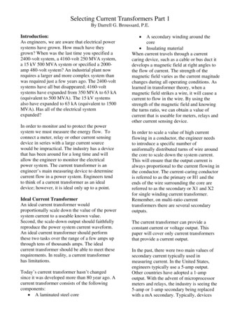
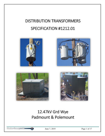
Material Specification 1212.01 Distribution Transformers – Padmount & PolemountLoss Evaluation3.2.1 Losses furnished for evaluation shall be guaranteed maximum losses for each transformer bid. Nodelivered unit shall exceed the guaranteed maximum losses. Guaranteed maximum losses shallcomply with DOE 2010 requirements for a single unit. (no averaging).3.2.2 No load losses (NLL) shall be in watts, at 20oC in accordance with ANSI C57.12.00 and shall beevaluated at 4.07 per watt.o3.2.3 Full-load losses (FLL) shall be in watts, measured at rated nameplate load at 85 C in accordance withANSI C57.12.00 and shall be evaluated at 1.79 per watt3.2.4 Evaluated Price Formula [ 4.07 x NLL] [ 1.79 x FLL] Unit Price – evaluation credit3.2.5 The manufacturer shall furnish with each transformer a certified test report of the no-load and full-loadlosses. The test report shall be submitted with the Contractor’s invoice.Adherence to SpecificationsThe District expects all bids to conform to these Specifications. Any exception is cause for rejection, at theDistrict’s discretion.Evaluation Credit 43% for being 50-100lbs under the maximum specified weight5% for being 150lbs or more under the maximum specified weightNo credit given between 101-149 lbs under the maximum specified weightINFORMATION TO BE FURNISHED WITH BID OR QUOTESee ITB-9, Bidder’s Data, for required information. Technical information shall be provided by Bidder with theirBid in a Microsoft Excel Spreadsheet on CD or USB thumb drive, and a paper copy of the same for all bid items.Outline and nameplate drawings shall be submitted with bid package. An electronic copy of the form isavailable; a sample form is shown below.June 7, 2019Page 4 of 17
Material Specification 1212.01 Distribution Transformers – Padmount & PolemountTable 1 : Technical Information Sample FormJune 7, 2019Page 5 of 17
Material Specification 1212.01 Distribution Transformers – Padmount & Polemount5POLEMOUNT TRANSFORMERSRatings5.1.1 All ratings shall be for 60 hertz alternating current, oil immersed, self-cooled transformers capable ofocontinuous operation at rated KVA without exceeding either a 65 C average temperature rise or an80oC hot spot temperature rise.5.1.2 The basic impulse level (BIL) shall be 95 kV.5.1.3 Overhead transformers shall have an impedance of 2.0%, 10%Pressure Relief Device5.2.1 All transformers shall be designed such that all excessive pressure build-ups are released withoutdamage to the tank in accordance with ANSI C57.12.25.5.2.2 All transformers shall be equipped with a pressure relief device (either Tomco Series 1776K orQualitrol Model 202-032-1). The threads shall be sealed with pipe dope.Transformer Taps5.3.1 No transformer taps are required.Transformer Oil5.4.1 Transformers shall be insulated with new (unused) mineral oil. The oil shall meet the requirements ofANSI C57.12.00, Article 6.6.1 (1), ANSI C57.106 and ASTM 3487 Type II. The transformernameplate shall indicate that the PCB content of said transformer is less than 1 PPM or at time ofmanufacture gas chromatographic analysis certified non-detectable PCB. The oil shall be inhibitedmineral oil containing 0.2 % by weight DBPC. The nameplate shall show the gallons of oil andstate the oil type as “Mineral Oil”.High Voltage Bushings and Terminals5.5.1 Transformers shall be equipped with cover-mounted, wet process porcelain high voltage bushings (twobushings) with clamp style terminals in accordance with ANSI C57.12.20, Table 7. The bushingsshall be light gray in color. The clamp type terminal shall be capable of being tightened with a Fargowrench (Fargo Manufacturing, Catalog No. GP-203).5.5.2 High voltage bushings shall be equipped with Reliaguard Handwheel Type Wildlife Guards which area hinged wildlife guard for use with handwheel tightened bushing terminals.Low Voltage Bushings and Terminals5.6.1 Transformers shall be equipped with side wall-mounted, low voltage bushings. Units 100 KVA andsmaller shall have clamp type terminals in accordance with ANSI C57.12.20, Figure 4a. Units 167KVA and larger shall have 4-hole square spade type terminals in accordance with ANSI C57.12.20,Figure 4b, Spade H.5.6.2 Transformers of 100kVA and larger shall have a bracket centered below the secondary bushings formounting cable supports for the secondary voltage wires.5.6.3 Number and arrangement of low-voltage terminals shall be in accordance with ANSI C57.12.20, Table9.5.6.4 Polymer secondary bushings shall be used for transformers.June 7, 2019Page 6 of 17
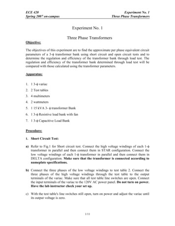
Material Specification 1212.01 Distribution Transformers – Padmount & PolemountTransformer Tanks5.7.1 Transformer tanks shall be of welded steel construction. The tank shall be a conventional, oil-filled,pole-type with only one pole-mounting position.5.7.2 The tank covers shall have a slope of 10-15 percent for moisture run-off and shall have an insulatedcoating on the cover capable of withstanding a minimum of 10kV at a 2000 volt/second rate of rise,tested per ASTM D149 using ¼” diameter electrodes.5.7.3 The overall size of the transformer and the weight of the transformers, once filled with oil, shall notexceed the following:Table 2: Single Phase Pole Mount Transformers – Max DimensionsSize(KVA)Weight(lbs.)Height (in.)*Width (in.)**Depth 2527758755125271001000503230167160054* Height shall bemeasured from bottom of tankto top of primary terminal attop of primary bushing.38** Widthshall be measuredfrom lifting hookto lifting hook.38*** Depth shall bemeasured from mountingbracket to outside ofsecondary terminal.5.7.4 Tanks shall have tank ground provisions and support lugs in accordance with ANSI StandardC57.12.20.Grounding Lugs5.8.1 Transformers shall be furnished with a minimum of 2 ground lugs. One installed in the transformerlow-voltage ground provision, and a second on the opposite side of the tank. The ground lugs shallbe a Fargo (Catalog No. BVC-207-FT with slim brass jam nut). Installed vertically on pole mounttransformers.June 7, 2019Page 7 of 17
Material Specification 1212.01 Distribution Transformers – Padmount & PolemountTIF and RIV Requirement5.9.1 TIF - Transformers shall be designed to meet REA Telephone Influence Factor (TIF) requirements, asdetailed in REA Specifications D-10. Transformer I-T tests shall be made in accordance with themethod described in IEEE Standard No. 469-1977, except as noted in REA Specifications D-10.REA Specification D-10 requires that the average overall I-T of the secondary windings pertransformer nameplate KVA shall not exceed the following limits:I-T per KVA120 Volts132 Volts22665.9.2 RIV - The Radio Influence Voltage (RIV) shall not (per REA Specification D-10) exceed 100 µV(average measurement) at 1 MHz measured at 110% of rated voltage in accordance with themethods outlined in ASA Publication C63.2, 1950, Appendix A, Figure 5. Dual voltagetransformers shall be tested on the highest connection.6PAD MOUNT TRANSFORMER – SINGLE PHASERatings6.1.1 All ratings shall be for 60 Hertz alternating current, oil immersed, self-cooled transformers capable ofcontinuous operation at rated KVA without exceeding either a 65oC average temperature rise or ano80 C hot spot temperature rise.6.1.2 The electrical characteristics of the completely assembled high and low voltage terminals shall be inaccordance with ANSI C57.12.25, Table 1 and Section 6.2.1.6.1.3 The basic impulse level (BIL) shall be 95 kV.Loop Feed6.2.1 Transformers will be suitable for loop feed.6.2.2 The minimum current-carrying capabilities of components for looped primary cable systems shall be200 Amps (continuous) and 10,000 Amps rms symmetrical for 0.17 sec. (short-time current rating)for transformers with or without high-voltage switching.Transformer Type6.3.1 Transformers shall be Type 2 in accordance with Figure 2a of ANSI C57.12.25Pressure Relief Device6.4.1 All transformers shall be designed such that all excessive pressure build-ups are released withoutdamage to the tank in accordance with ANSI C57.12.25.6.4.2 All transformers shall be equipped with a pressure relief device (either Tomco Series 1776K orQualitrol Model 202-032-1). The threads shall be sealed with pipe dope.Transformer Taps6.5.1 No transformer taps are required.June 7, 2019Page 8 of 17
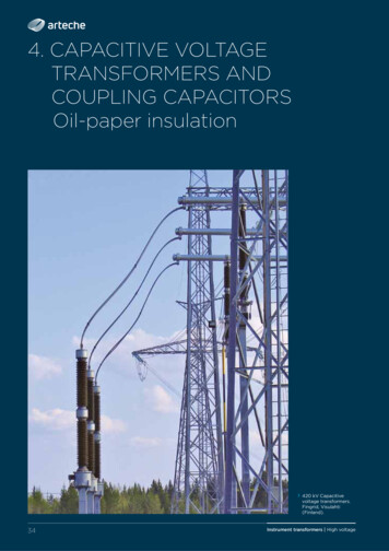
Material Specification 1212.01 Distribution Transformers – Padmount & PolemountHigh Voltage Bushings6.6.1 Transformers shall come equipped with two high voltage bushing wells and corresponding load breakinserts for dead front application. The bushing wells shall be externally clamped, 200-amp rated,separable, and rated for primary switching per IEEE 386.6.6.2 The bushings shall conform to ANSI C57.12.25, Type 2 arrangement.6.6.3 The load-break bushing inserts shall be Cooper Power Systems LBI 215 or Elastimold (Catalog No.1601A4).6.6.4 Inserts shall be shipped with physically wired down & secured dust caps or use a dust cap equippedwith a pressure relief hole to prevent pressure build up in the dust cap that would cause loss of thedust cap.Low Voltage Bushings6.7.1 Transformers shall be equipped with fully insulated, low voltage bushings with in-line NEMA standardstud terminals in accordance with Figure 4C of ANSI C57.12.25.6.7.2 Transformers shall be furnished with the following terminals:Table 3: Single Phase Padmount – Terminal SizeKVASecondaryVoltageTerminal Size25-7524
07.06.2019 · ANSI C57.12.00, Article 6.6.1 (1), ANSI C57.106 and ASTM 3487 Type II. The transformer nameplate shall indicate that the PCB content of said transformer is less than 1 PPM or at time of manufacture gas chromatographic analysis certified non-detectable PCB. The oil shall be inhibited mineral oil containing 0.2 % by weight DBPC. The nameplate shall show the gallons of oil and