Transcription
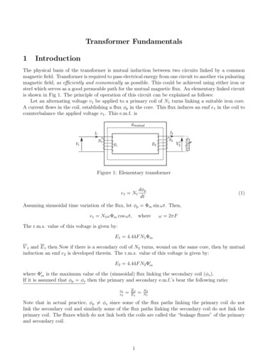
Transformer Fundamentals1IntroductionThe physical basis of the transformer is mutual induction between two circuits linked by a commonmagnetic field. Transformer is required to pass electrical energy from one circuit to another via pulsatingmagnetic field, as efficiently and economically as possible. This could be achieved using either iron orsteel which serves as a good permeable path for the mutual magnetic flux. An elementary linked circuitis shown in Fig 1. The principle of operation of this circuit can be explained as follows:Let an alternating voltage v1 be applied to a primary coil of N1 turns linking a suitable iron core.A current flows in the coil, establishing a flux φp in the core. This flux induces an emf e1 in the coil tocounterbalance the applied voltage v1 . This e.m.f. isFigure 1: Elementary transformere1 N1dφpdt(1)Assuming sinusoidal time variation of the flux, let φp Φm sin ωt. Then,e1 N1 ωΦm cos ωt,whereω 2πFThe r.m.s. value of this voltage is given by:E1 4.44F N1 ΦmV 1 and E 1 then Now if there is a secondary coil of N2 turns, wound on the same core, then by mutualinduction an emf e2 is developed therein. The r.m.s. value of this voltage is given by:E2 4.44F N2 Φ0mwhere Φ0m is the maximum value of the (sinusoidal) flux linking the secondary coil (φs ).If it is assumed that φp φs then the primary and secondary e.m.f.’s bear the following ratio:e1e2 E2E1 N2N1Note that in actual practice, φp 6 φs since some of the flux paths linking the primary coil do notlink the secondary coil and similarly some of the flux paths linking the secondary coil do not link theprimary coil. The fluxes which do not link both the coils are called the “leakage fluxes” of the primaryand secondary coil.1
In a practical transformer a very large proportion of the primary and secondary flux paths arecommon and leakage fluxes are comparatively small. Therefore φp φs φmutual and therefore Φm Φ0m .If in addition, winding resistances are neglected – being usually small in a practical transformer, thenV 1 E1Similarly,V 2 E22Magnetization and associated lossesAlthough the iron core is highly permeable, it is not possible to generate a magnetic field in it withoutthe application of a small m.m.f.(magneto-motive force), denoted by Mm . Thus even when the secondary winding is open circuited, a small magnetizing current (im ) is needed to maintain the magneticflux. The current of the primary circuit on no-load is of the order of 5% of full load current.Also, the pulsation of flux in the core is productive of core loss, due to hysteresis and eddy currents.These losses are given by:1.6Ph Kh BmaxF,2Pe Ke BmaxF2and Pc Ph Pewhere Ph , Pe and Pc are hysteresis, eddy current and core losses respectively, Kh and Ke are constantswhich depend on the magnetic material, and Bmax is the maximum flux density in the core. These losseswill remain almost constant if the supply voltage and frequency are held constant. The continuous lossof energy in the core requires a continuous supply from the electrical source to which the primary isconnected. Therefore, there must be a current component ic which accounts for these losses. It shouldbe noted that magnetizing current (im ) and core loss component of current(ic ) are in phase quadrature.The resultant of these two currents is the no-load current io . Generally the magnitude of this currentis very small compared to that of the rated current of the transformer ( may be of the order of 5% ofthe rated). This current makes a phase angle ζo of the order of (cos 1 (0.2)) with the applied voltage.3Ideal transformerIf a load of finite impedance is connected across the second coil, a current i2 will flow through it. Thistends to alter the mmf and thereby the flux in the core. But this is prevented by an immediate andautomatic adjustment of the primary current i1 , thereby maintaining the flux φ at the original value.This value of flux is required to produce the emf of self induction e1 . Any reduction of the flux wouldcause a reduction of e1 , leaving a voltage difference between v1 and e1 which would be sufficient toincrease the primary current and thereby re-establish the flux. Thus any current which flows in thesecondary causes its counterpart to flow in the primary so that the flux φ (and therefore the mmf Mm ) shall always be maintained at a value such that the voltage applied v1 to the primary terminalsshall be balanced by the induced emf e1 (neglecting voltage drops due to resistance and leakage fluxN2i2 so that effective mmf in theeffects). Thus if current flows in the secondary (i2 ), then i1 io N1core remains at Mm . In phasor notation:I1 Io 2N2IN1 2
I o is quite small compared to the rated current and is usually neglected if transformer is loaded. Thus:I1 N2IN1 2It is therefore, evident that energy is conveyed from the primary to secondary by the flux: the primarystores the energy in the magnetic field, and an extraction of some of this for the secondary load is madeup by the addition of energy from the primary, which consequently takes an increased current.Thus by making the assumptions : Winding resistances are small Magnetising current is small Core losses are small Leakage fluxes are smallwe can infer that (for an “ideal transformer”):I1E2V2N2 N1I2E1V13.1(2)Equivalent Circuit of a practical TransformerThe practical transformer has coils of finite resistance. Though this resistance is actually distributeduniformly, it can be conceived as concentrated. Also, all the flux produced by the primary currentcannot be confined into a desired path completely as an electric current. Though a greater proportionlinks both the coils( known as mutual flux), a small proportion called the leakage flux links one or otherwinding, but not both. It does not contribute to the transfer of energy from primary to secondary. Onaccount of the leakage flux, both the windings have a voltage drop which is due to ‘leakage reactance’.The transformer shown in Fig. 1 can be resolved into an equivalent circuit as shown in Fig. 2 in whichthe resistance and leakage reactance of primary and secondary respectively are represented by lumpedR1 , X1 , R2 and X2 . This equivalent circuit can be further simplified by referring all quantities in thesecondary side of the transformer to primary side and is shown in Fig. 3. These referred quantities aregiven by:Figure 2: Equivalent circuit of a transformer1 2)R20 R2 ( NN2N1 2X20 X2 ( N)2N2I20 I2 ( N)11V20 V2 ( N)N2Generally the voltage drops I1 R1 and I1 X1 are small and magnitude of E 1 is approximately equal tothat of V 1 . Under this condition, the shunt branch (comprising Xm and Ro ) can be connected acrossthe supply terminals. This approximate equivalent circuit (shown in Fig. 4) simplifies the computationof currents and other performance characteristics of a practical transformer.3
Figure 3: Reduced equivalent circuit of a transformerFigure 4: Simplified equivalent circuit of a transformer4EfficiencyEfficiency of the transformer is defined as:output powerη input powerInterms of losses,η output poweroutput power iron losses copper lossesLet ‘S’ be the rated VA of the transformer, ‘x’ is the fraction of full load the transformer is supplying,and ζ is the load power factor angle. Under this condition the output power of the transformer is x.S. cos ζ. If Pc is the copper loss (loss in winding resistance) at rated current, the corresponding losswhile supplying the fraction of load is x2 .Pc . With transformers of normal design, the flux in thecore varies only a few percent between no-load to full load. Consequently it is permissible to regard thecore loss ( iron loss) as constant, regardless of load. Let this loss be Pi . Therefore equation becomes :η 5x.S. cos ζx.S. cos ζ Pi Pc .x2RegulationFrom Fig. 4 it can be seen that if the input voltage is held constant, the voltage at the secondaryterminals varies with load. Regulation is defined as the change in magnitude of secondary (terminal)voltage, when the load is thrown off with primary voltage held constant. Since, the change in secondaryvoltage depends only on the load current, the equivalent circuit is further simplified and is shown inFig. 5. The phasor diagrams for lagging, unity and leading powerfactor loads are shown in Fig. 6 to4
Figure 5: Equivalent circuit to determine regulationFigure 6: Phasor diagram for lagging power factorFig. 8. It can be proved that angle σ is very small and can be neglected. In that case, the expressionfor regulation is given byI20 .Req . cos ζ I20 .Xeq . sin ζ 100%regulation V20where, I20 load current,Req R1 R20 ,.‘ ’ for lagging pf and ‘ ’ for leading pf (3)Xeq X1 X20 ,Figure 7: Phasor diagram for leading power factor5
Figure 8: Phasor diagram for unity power factorNote to TAs/RAs: Open the cover of the transformer and show the students HV and LV terminals, conductors used for LV and HV winding. Also show them E & I laminations, and ferrite core.Also, conduct the no-load test on high frequency ferrite core transformer at 50 Hz (using single phase ac source). Ask the students to observe the deflection on the ammeteras you increase the voltage. Observe the current waveform on the power analyzer. Note down themagnitude of applied voltage. about 10 kHz (use the signal generator) and observe the waveforms on the storage oscilloscope. Notedown the magnitude of applied voltage.11This experiment/chapter is prepared by Makarand M Kane (Research Scholar, 2015 batch).6
A current ows in the coil, establishing a ux p in the core. This ux induces an emf e 1 in the coil to counterbalance the applied voltage v 1. This e.m.f. is Figure 1: Elementary transformer e 1 N 1 d p dt (1) Assuming sinusoidal time variation of the ux, let p msin!t. Then, e 1 N 1! mcos!t; where ! 2ˇF The r.m.s. value of this voltage is given by: E 1 4:44FN 1 m V 1 and E 1 .