Transcription
User Instruction ManualFixed Beam AnchorThis manual is intended to meet theManufacturer’s Instructions as requiredby ANSI Z359.1 and ANSI A10.14, andshould be used as part of an employeetraining program as required by OSHA. Copyright 2002 DB Industries, Inc.
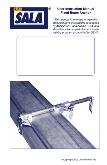
Figure 1 - Fixed Beam Anchor3
WARNING: This product is part of a personal fall protection system. Theuser must read and follow the manufacturer’s instructions for eachcomponent of the system. These instructions must be provided to the userof this equipment. The user must read and understand these instructionsbefore using this equipment. Manufacturer’s instructions must be followedfor proper use and maintenance of this equipment. Alterations or misuseof this equipment, or failure to follow instructions, may result in seriousinjury or death.IMPORTANT: If you have questions on the use, care, or suitability of thisequipment for your application, contact DBI/SALA.IMPORTANT: Record the product identification information from the IDlabel in the inspection and maintenance log in section 9.0 of this manual.DESCRIPTIONThe Fixed Beam Anchor is available in five models:2108406: For beam flange sizes 2-1/2 inches to 12 inches wide, up to 1-1/2inches thick.2108407: For beam flange sizes 2-1/2 inches to 18 inches wide, up to 1-1/2inches thick.2108408: For beam flange sizes 2-1/2 inches to 24 inches wide, up to 1-1/2inches thick.2108410: For beam flange sizes 12 inches to 36 inches wide, up to 2-1/2inches thick.2108411: For beam flange sizes 3 inches to 15 inches wide, up to 2-1/2inches thick.Figure 2 - Beam Flange Application Sizes4
1.0APPLICATIONS1.1PURPOSE: The Fixed Beam Anchor is an anchorage connector for apersonal fall arrest system, designed to be attached to a beam. TheFixed Beam Anchor may be used as an end termination for DBI/SALAapproved horizontal lifeline systems.1.2LIMITATIONS: The following application limitations must beconsidered before using this equipment:A. BEAM FLANGE SIZES: The Fixed Beam Anchor may only beinstalled on beams with flanges within the adjustment range ofthe model. See Figure 2.B. CAPACITY: This equipment is designed for use by persons witha combined weight (clothing, tools, etc.) of no more than 310 lbs.No more than one personal protective system may be connectedto this equipment at one time. When this equipment is used as anend termination for a horizontal lifeline the maximum capacity is2,500 lbs.C. PERSONAL FALL ARREST SYSTEM: The personal fall arrestsystem used with this equipment must meet the requirementsspecified in section 2.1.D. FREE FALL: Personal fall arrest systems used with thisequipment must be rigged to limit the free fall to a maximum ofsix feet when possible, as required by OSHA. The maximum freefall must always be within the manufacturer's free fall capacity ofthe system components used to arrest the fall. See section 2.1and connecting subsystemmanufacturer’s instructionsFigure 3 - Swing Fall Hazardfor more information.E. SWING FALLS: See Figure 3.Swing falls occur when theanchorage point is not directlyabove or below the pointwhere a fall occurs. The forceof striking an object in aswing fall may cause seriousinjury or death. Minimize swingfalls by working as close tothe anchorage as possible.Do not permit a swing fall ifinjury could occur. Swing fallswill significantly increase the5
clearance required when a self retracting lifeline or other variablelength connecting subsystem is used.F.FALL CLEARANCE: There must be sufficient clearance belowthe user to arrest a fall before the user strikes the ground or otherobstruction. The clearance required is dependent on the followingfactors: Elevation of Fixed Beam AnchorLength of connecting subsystemDeceleration distanceMovement of harness attachment element (sliding D-ring)Worker heightFree fall distanceSee personal fall arrest system manufacturer’s instructions formore information.G. ENVIRONMENTAL HAZARDS: Use of this equipment in areaswith environmental hazards may require additional precautions toreduce the possibility of injury to the user or damage to theequipment. Hazards may include, but are not limited to; heat,chemicals, corrosive environments, high voltage power lines,gases, moving machinery, and sharp edges. Contact DBI/SALA ifyou have questions about using this equipment whereenvironmental hazards exist.H. TRAINING: This equipment must be installed and used bypersons trained in its correct application and use. See section 4.0.1.32.02.1APPLICABLE STANDARDS: Refer to national standards, includingANSI Z359.1, ANSI A10.14, and local, state, and federalrequirements for more information personal fall arrest systems andassociated components.SYSTEM REQUIREMENTSPERSONAL FALL ARREST SYSTEM: The Fixed Beam Anchor isdesigned for use with DBI/SALA approved components orsubsystems. Use of this equipment with non-approved componentsmay result in incompatibility between equipment, and could affect thereliability and safety of the complete system. Personal fall arrestsystems used with this equipment must meet applicable OSHA, state,federal, and ANSI requirements. A full body harness must be worn bythe worker when connected to the Fixed Beam Anchor. As requiredby OSHA, the personal fall arrest system must be capable of6
arresting a worker’s fall with a maximum arresting force no greaterthan 1,800 lbs., and where possible, limit the free fall distance to sixfeet or less. If the maximum free fall distance of six feet must beexceeded, the employer must be able to document, based on testdata, that the maximum permissible arresting forces will not beexceeded, and that the personal fall arrest system will functionproperly.When a free fall greater than six feet and up to a maximum of twelvefeet is possible, DBI/SALA recommends using a personal fall arrestsystem incorporating a DBI/SALA Force2 energy absorbing lanyard.DBI/SALA has performed testing using the Force2 energy absorbinglanyard in free falls up to twelve feet to ensure the maximum arrestingforce does not exceed 1,800 lbs., and the system functions properly.The results of these tests are listed in the user instruction manualprovided with Force2 shock absorbing lanyards.2.2COMPATIBILITY OF COMPONENTS: DBI/SALA equipment isdesigned for use with DBI/SALA approved components andsubsystems only. Substitutions or replacements made with nonapproved components or subsystems may jeopardize compatibility ofequipment and may effect the safety and reliability of the completesystem.2.3COMPATIBILITY OF CONNECTORS: Connectors are considered tobe compatible with connecting elements when they have beendesigned to work together in such a way that their sizes and shapesdo not cause their gate mechanisms to inadvertently open regardlessof how they become oriented. Contact DBI/SALA if you have anyquestions about compatibility.Connectors ( hooks, carabiners, and D-rings) must be capable ofsupporting at least 5,000 lbs. (22kN). Connectors must be compatiblewith the anchorage or other system components. Do not useequipment that is not compatible. Non-compatible connectors mayunintentionally disengage. See Figure 4. Connectors must becompatible in size, shape, and strength. Self locking snap hooks andcarabiners are required by ANSI Z359.1 and OSHA.2.4Making Connections: Only use self-locking snap hooks andcarabiners with this equipment. Only use connectors that are suitableto each application. Ensure all connections are compatible in size,shape and strength. Do not use equipment that is not compatible.Ensure all connectors are fully closed and locked.DBI/SALA connectors (snap hooks and carabiners) are designed tobe used only as specified in each product’s user’s instructions. See7
Figure 4 - Unintentional Disengagement (Roll-out)If the connecting element that a snap hook (shown) or carabiner attachesto is undersized or irregular in shape, a situation could occur where theconnecting element applies a force to the gate of the snap hook orcarabiner. This force may cause the gate (of either a self-locking or anon-locking snap hook) to open, allowing the snap hook or carabiner todisengage from the connecting point.Small ring or othernon-compatibilityconector1. Force is applied tothe snap hook.2. The gate pressesagainst theconnecting ring.3. The gate opensallowing the snaphook to slip off.Figure 5 for inappropriate connections. DBI/SALA snap hooks andcarabiners should not be connected:A. To a D-ring to which another connector is attached.Figure 5 - Inappropriate Connections8
B. In a manner that would result in a load on the gate.NOTE: Large throat opening snap hooks should not be connected tostandard size D-rings or similar objects which will result in a load on thegate if the hook or D-ring twists or rotates. Large throat snap hooks aredesigned for use on fixed structural elements such as rebar or crossmembers that are not shaped in a way that can capture the gate of the hook.C. In a false engagement, where features that protrude from thesnap hook or carabiner catch on the anchor and without visualconfirmation seems to be fully engaged to the anchor point.D. To each other.E. Directly to webbing or rope lanyard or tie-back (unless themanufacturer’s instructions for both the lanyard and connectorspecifically allows such a connection).F.2.5To any object which is shaped or dimensioned such that the snaphook or carabiner will not close and lock, or that roll-out couldoccur.ANCHORAGE STRENGTH: Fixed Beam Anchors installed for fallarrest applications must be attached to a beam structure capable ofsustaining static loads in the directions permitted by the personal fallarrest system when in use of at least; (A) 3,600 lbs. when certificationexists (see ANSI Z359.1 for certification definition), or (B) 5,000 lbs.in the absence of certification. When the Fixed Beam Anchor is usedto terminate a horizontal lifeline system the structure must have aminimum strength (C) equal to twice the maximum load applied to theFixed Beam Anchor during a fall. When more than one Fixed BeamAnchor is secured to the same beam, all points of the beam must becapable of supporting the strengths given in (A), (B), or (C) for eachFixed Beam Anchor on that beam. Per OSHA 1926.500 and 1910.66:Anchorages used for attachment of a personal fall arrest system shallbe independent of any anchorage being used to support or suspendplatforms, and must support at least 5,000 lbs. per user attached; orbe designed, installed, and used as part of a complete personal fallarrest system which maintains a safety factor of at least two, and issupervised by a qualified person.9
3.0INSTALLATION AND USEWARNING: Do not alter or intentionally misuse this equipment. ConsultDBI/SALA when using this equipment in combination with components orsubsystems other than those described in this manual. Some subsystemand component combinations may interfere with the operation of thisequipment. Use caution when using this equipment around movingmachinery, electrical hazards, chemical hazards, and sharp edges.WARNING: Consult your doctor if there is reason to doubt your fitness tosafely absorb the shock from a fall arrest. Age and fitness seriously affecta worker's ability to withstand falls. Pregnant women or minors must notuse DBI/SALA anchorage connectors.3.1BEFORE EACH USE of this equipment inspect it according tosection 5.0 of this manual.3.2INSTALLATION: The Fixed Beam Anchor may be installed on anybeam flange and location meeting the requirements specified insection 1.2. The Fixed Beam Anchor may be installed on the beam asshown in Figure 6.Step 1.Remove detent pin. Open the adjustable beam hook byturning the adjustment handle counter-clockwise.Figure 6 - Installation Configurations10
Step 2.Place Fixed Beam Anchor onto beam flange in your requiredposition (top, bottom, side). Note: Fasteners or otherobstructions may prevent the Fixed Beam Anchor fromproperly securing to the beam. Move the Fixed Beam Anchorto another location if obstructions interfere with installation.Step 3.Place fixed beam hook against one side of the beam flange.Slide the adjustable beam hook against opposite side ofbeam flange.Step 4.Hold adjustment handle parallel with the support tube. Turnadjustment handle to align the hole in the adjustment blockwith nearest hole in support tube.Step 5.Insert detent pin through adjustment block and support tube,ensuring pin is locked into place.Step 6.To secure the Fixed Beam Anchor onto the flange, pivot theadjustment handle away from the support tube and turnadjustment handle clockwise in half turns. Ensure beamhooks are tight against both sides of the flange. Hand tightenonly. Ensure the adjustment pin has not bottomed out. SeeFigure 7. If adjustment pin has bottomed out reinstall theFixed Beam Anchor using the next hole closer to the beamflange to allow travel for the adjustment pin.Figure 7 - Adjustment Pin Travel3.3USING THE FIXED BEAM ANCHOR:A. PERSONAL FALL ARREST SYSTEM: Inspect and don your fullbody harness according to manufacturer’s instructions. Attach theconnecting subsystem (energy absorbing lanyard) to the dorsalD-ring on the harness.11
B. STRUCTURE: Ensure the structure you will be connecting to isproperly supported before using this equipment. Approach thestructure using appropriate access equipment.C. OTHER CONSIDERATIONS: When working on a structure donot take unnecessary risks, such as jumping or reaching too farfrom the edge. Be aware of all environmental hazards in the area.Do not allow your connecting subsystem to pass under your armsor between your feet. To avoid inadequate fall clearance, do notclimb above or to the side of the Fixed Beam Anchor.D. SHARP EDGES: Avoid working where the connecting subsystem(energy absorbing lanyard) or other system components will be incontact with, or abrade against, unprotected sharp edges. Ifworking around sharp edges is unavoidable, protection againstcutting must be provided through the use of a protective cover.E. IN THE
ANSI Z359.1, ANSI A10.14, and local, state, and federal requirements for more information personal fall arrest systems and associated components. 2.0 SYSTEM REQUIREMENTS 2.1 PERSONAL FALL ARREST SYSTEM: The Fixed Beam Anchor is designed for use with DBI/SALA approved components or subsystems. Use of this equipment with non-approved components
