Transcription
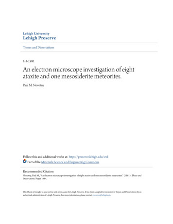
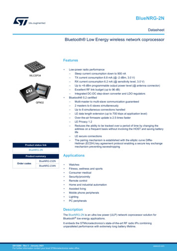
Advances in Low Energy Electron Beam Equipment TechnologyTerrance W. ThompsonPCT Engineered Systems, LLC - USAElectron beam (EB) technology has been used in industrial applications for more than 30 years.The use of EB is driven by a number of factors including: improved product performance,product consistency, high throughput, energy savings, and environmental advantages. Thenature of EB technology can also enable unique applications that are not possible by othermeans. Recent advances in equipment technology are helping to expand the applications forelectron beam systems that now range from 15 kV to 175 kV.Most of the recent developments in EB equipment have focused on “low energy” systems.These systems typically operate in the range of about 70 to 150 kV. This equipment is wellsuited for curing of inks and coatings used in package printing applications and can also addressa variety of non-printing converting applications. However, users and potential users of EBtechnology continue to ask more from the suppliers of this equipment. Requests include: Lower capital costsImproved reliabilityLower cost of operationEasy and inexpensive maintenanceWider ranges of voltagesCustomization for new applicationsLarger range of web widthsNon-web product handlingNew applications are demanding smaller more efficient systems that can integrate directly intoexisting and new process lines. Equipment providers are responding to these requests and areintroducing innovative new designs that leverage advances in technology and years of experiencewith industrial EB systems.This paper summarizes new low energy EB equipment developments and compares thesedevelopments against the needs of the market.Ultra-Low Energy Electron Beam SystemsTraditional low energy electron beam equipment uses an electron gun within a vacuum chamber.The electrons are accelerated though a thin titanium foil window to allow treatment of materialsat atmospheric pressure. In order to minimize energy deposition in the foil most EB equipmentoperates at a minimum voltage of about 70 to 90 kV. A new innovative electron beamtechnology is now available for curing/treating materials within a vacuum chamber. Since theelectrons do not need to penetrate a foil layer they can be accelerated in an “ultra-low” energyrange of 15 kV to 25 kV. The ultra-low energy EB systems are designed to be installed directlyinto a vacuum coating chamber. A representative ultra-low energy EB unit (installed in a vacuumtest fixture) is shown in Figure 1. Applications for ultra-low energy EB include curing coatings
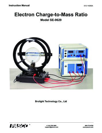
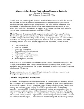
that are vacuum deposited or roll coated on a web within the vacuum chamber. These coatingscan be used in combination with metallization or other processes within the vacuum chamber.The EB equipment is designed to operate in the 10-5 torr range used in many vacuum coatingprocesses.Figure 1. Ultra-Low energy electron beam for vacuum applications(electron gun within vacuum test fixture).A dept/dose curve generated from a Monte Carlo simulation for an EB unit operating at 15 kV ina 10-5 torr vacuum is shown in Figure 2. This curve shows that 15 kV electrons can penetratecoating weights up to about 4 g/m2 (4 microns for coatings with a density of 1.0 g/cm3).Ultra-low energy electron beam systems are available to accommodate product widths from 20inches to over 90 inches. The ultra-low energy systems include digital operated power supplieswhich offer high efficiency and precise control.2.50Relative EB Dose2.001.501.000.500.0001234Depth of Penetration (g/m2)5Figure 2. Depth/dose curve for 15 kV EB operated in 10-5 torr.
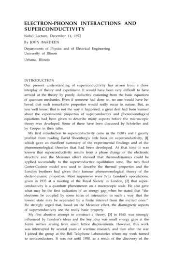
Integrated Shield RollAll EB systems require shielding to protect personnel from the x-rays that are generated by theinteraction of the electrons with materials in the equipment. Low energy EB systems can be selfshielded such that all of the required shielding is integral to the system. The amount of shieldingmaterial required varies with the energy level of the machine.Chill rolls have been utilized in EB systems for many years. When a chilled roll is used tosupport the material as it is exposed to the electrons the distance between the material and thewindow where the electrons are emitted is precisely fixed. This ensures that any variations in theamount of energy delivered to the material are minimized. Even small changes in this distancewill have a significant effect on the amount of energy when operating at low voltage levels.Supporting the material with a chill roll also is beneficial when processing plastic films. Thisdesign minimizes any potential for temperature rise in the material. It also facilitates the use ofheat sensitive films such as films used in the production of shrink sleeve labels.An innovative new design has been introduced that uses an integral chill roll as the shield roll forproper radiation shielding. This technology can be used for EB systems up to 300kV. Thispatented (US 8,106,369) design uses a temperature controlled roll to support the material whilethe roll simultaneously serves as a functional portion of the required shielding. The roll isprecisely fit to the mating surfaces. The results are reduced size and materials, minimization ofthe volume that must be inerted with nitrogen, and easy access for threading and cleaning. Theexposed roll surface is also ideal for integrating other processes such as coating heads, extruders,nip rolls, etc.Figure 3. Integrated shield roll EB system.
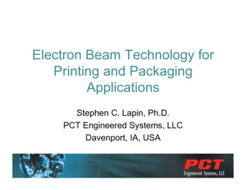
Low ProfileAdvances in printing press technology targeted at the flexible package market have opened moreopportunities for EB systems. An important package printing technology is the use of variablesleeves on web offset presses. This style of press requires the EB system to accept a low webentry height. The web height will also vary as the sleeve diameters change. The latest EB systemdesigns accommodate these web handling requirements and maintain a “side fire” orientation.The “side fire” orientation is preferred for the maintenance access that is required to perform awindow foil change. The small size of this design also facilitates easier retrofits onto existingproduction lines starting at a press exit height of 24 inches (600mm).Figure 4. Low profile EB system.Extended Voltage Low Energy Systems.The first generation of more compact, lower cost EB equipment was introduced about 10 yearsago. This equipment operated in the range of 80 to 125 kV which was suitable for curingrelatively thin layers of inks and coatings. Curing or crosslinking of thicker materials requiredindustrial EB processors operating from 150 to 300 kV. Recently new compact equipment wasintroduced operating at up to 150 kV. This range has now been extended up to 175 kV. Thesehigher energies allow one-side treatment of materials up to 150 g/m2 (150 microns for materialswith a density of 1.0 g/cm3). The ability to have these designs extend up to 175 kV allows theuse of electron beams in applications such as crosslinking of film or pressure sensitive adhesivesat prices that generate an attractive rate of return on investment. An example of a compact lowercost EB unit operating up to 175 kV is shown in Figure 5. This unit also incorporates theintegrated shield roll technology discussed above.
Figure 5. Extended voltage (175 kV) electron beam equipment.Digital High Voltage Power SupplyThe high voltage power supply is a significant component in an EB system. The power supplytechnology used impacts the equipment’s reliability, controllability, and energy consumption. EBsystems have been introduced that now use high frequency switch-mode power supplies. Thehigh frequency switching of the power transistors minimizes the voltage ripple to give a powerfactor above 0.90. This contributes to reduced electrical power consumption. This style of powersupply is also digitally controlled providing arc response times of 50 microseconds. The digitalcontrols can be easily integrated with the EB system controls via Ethernet connections.A power supply rated for outputs above 30 kV will use an insulating material in the transformersection. Some power supply designs use sulfur hexafluoride (SF6) gas for this purpose. SF6 hasbeen identified as a greenhouse gas air pollutant by the U.S. EPA. It has a global warmingpotential 23,900 times greater than CO2. This latest generation of power supplies uses siliconefluid for electrical insulation. The silicone fluid also results in a cost savings compared to thehigher cost SF6 gas.
Figure 6. High voltage power supplyEB Systems Based on Sealed Tube EmittersSealed tube EB emitters have been in the industry for several years. Recent advances in thereliability and configurations now allow these emitters to be applied in more industrialapplications (RadTech Europe 2011, Comet AG Technical Paper 4.2). Integration of theseemitters into appropriate shielding configurations allows processing of a wide variety ofmaterials including webs, flat materials, and three-dimensional (3-D) objects. Current sealedtube emitters are 16 inches (400 mm) wide and allow processing at speeds up to 100 m/min (30kGy dose) with voltages ranging from 90 to 180 kV.Web applications for EB systems based on sealed tube emitters may include narrow webprinting, coating, and crosslinking. Potential applications for narrow web printing include: The curing of thick and / or high density ink layersSupplemental curing of current UV inksCuring of EB inks and coatings designed for food packagingEB adhesive laminationEB cold foil transferNarrow web configurations can incorporate integrated shield rolls for precise material handlingand temperature control during the curing process (Figure 7).
Figure 7. Narrow web EB sytem with sealed tube emitter and integrated shield roll.Historically low energy self-shielded EB applications have mainly been limited to processingwebs and flat materials. With the advent of reliable small format sealed tube emitters 3-Dapplications are now possible. One or more emitters may be configured along with automatedproduct transport to allow curing on the desired surfaces. An example of a system designed for3-D curing is shown in Figure 8.Figure 8. Custom 3-D curing application with a sealed beam emitter.
ConclusionsThere are a number of new developments in low energy EB equipment that have been recentlyintroduced. Table 1 shows that these developments are well suited to address the needs of themarket for EB equipment. These developments in equipment technology will continue tofacilitate the growth of new EB applications.Table 1. New Low Energy EB Equipment Fit with Market NeedsDevelopmentUltra-lowenergy EBLow ProfileIntegratedShield RollExtendedvoltageSealed tubeemittersDigital HighVoltage Market nceXXXXXXXXXXXXXXXXXXXXXXXXXXXXXXXXXXXXXX
PCT Engineered Systems, LLC - USA !! Electron beam (EB) technology has been used in industrial applications for more than 30 years. The use of EB is driven by a number of factors including: improved product performance, product consistency, high thro