Transcription
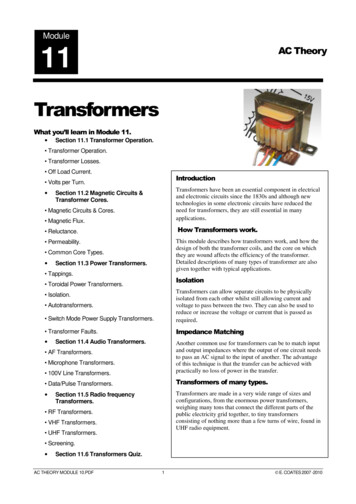
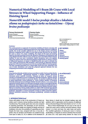
Module 7Simple Beam TheoryLearning Objectives Review simple beam theory Generalize simple beam theory to three dimensions and general cross sections Consider combined effects of bending, shear and torsion Study the case of shell beams7.1Review of simple beam theoryReadings: BC 5 Intro, 5.1A beam is a structure which has one of its dimensions much larger than the other two.The importance of beam theory in structural mechanics stems from its widespread successin practical applications.7.1.1Kinematic assumptionsReadings: BC 5.2Beam theory is founded on the following two key assumptions known as the EulerBernoulli assumptions: Cross sections of the beam do not deform in a significant manner under the applicationof transverse or axial loads and can be assumed as rigidConcept Question 7.1.1. With reference to Figure 7.1,1. what is the main implication of this assumption on the kinematic description(overall displacement field) of the cross section?91
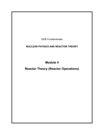
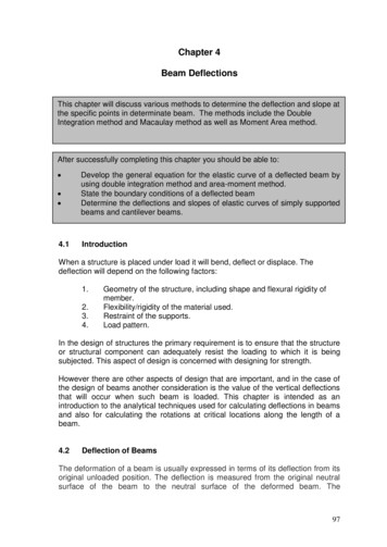
92MODULE 7. SIMPLE BEAM THEORYe3e2u3e1u2Figure 7.1: First kinematic assumption in Euler-Bernoulli beam theory: rigid in-plane deformation of cross sections.2. To simplify further the discussion, assume for now that there is no rotation of thecross section around the e3 axis. Write the most general form of the cross-sectionin-plane displacement components: During deformation, the cross section of the beam is assumed to remain planar andnormal to the deformed axis of the beam.Concept Question 7.1.2. With reference to Figure 7.3,1. what is the main implication of this assumption on the kinematic description(overall displacement field) of the cross section?2. Based on these kinematic assumptions, write the most general form of the crosssection out-of-plane displacement component:3. If you noticed, we have not applied the constraint that the sections must remainnormal to the deformed axis of the beam. Use this part of the assumption toestablish a relation between the displacements fields ū2 (x1 ), ū3 (x1 ) and the anglefields θ2 (x1 ), θ3 (x1 ), respectively, see Figure ?.Concept Question 7.1.3. Combine the results from all the kinematic assumptions toobtain a final assumed form of the general 3D displacement field in terms of the threeunknowns ū1 (x1 ), ū2 (x1 ), ū3 (x1 ):
7.1. REVIEW OF SIMPLE BEAM THEORY93e3e3e2e2e1e1θ2 (x1 )(a)(b)e3e2θ3 (x1 )e1(c)Figure 7.2: Second kinematic assumption in Euler-Bernoulli beam theory: cross sectionsremain planar after deformation.
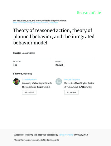
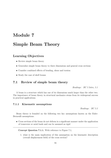
94MODULE 7. SIMPLE BEAM THEORYθ2e3θ3e2u3 (x1 )e2 bcu2 (x1 )e3e1(a)bbce1(b)Figure 7.3: Implications of the assumption that cross sections remain normal to the axis ofthe beam upon deformation.These assumptions have been extensively confirmed for slender beams made of isotropicmaterials with solid cross-sections.Concept Question 7.1.4. Use the kinematic assumptions of Euler-Bernoulli beam theoryto derive the general form of the strain field:Concept Question 7.1.5. It is important to reflect on the nature of the strains due tobending. Interpret the components of the axial strain 11 in Euler-Bernoulli beam theoryOne of the main conclusions of the Euler-Bernoulli assumptions is that in this particular beam theory the primary unknown variables are the three displacement functionsū1 (x1 ), ū2 (x1 ), ū3 (x1 ) which are only functions of x1 . The full displacement, strain and therefore stress fields do depend on the other independent variables but in a prescribed way thatfollows directly from the kinematic assumptions and from the equations of elasticity. Thepurpose of formulating a beam theory is to obtain a description of the problem expressedentirely on variables that depend on a single independent spatial variable x1 which is thecoordinate along the axis of the beam.7.1.2Definition of stress resultantsReadings: BC 5.3Stress resultants are equivalent force systems that represent the integral effect of theinternal stresses acting on the cross section. Thus, they eliminate the need to carry over thedependency of the stresses on the spatial coordinates of the cross section x2 , x3 .
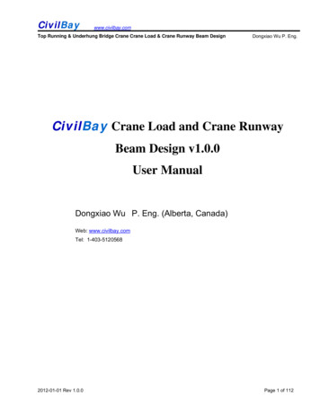
7.2. AXIAL LOADING OF BEAMS95The axial or normal force is defined by the expression:ZN1 (x1 ) σ11 (x1 , x2 , x3 )dA(7.1)AThe transverse shearing forces are defined by the expressions:ZV2 (x1 ) σ12 (x1 , x2 , x3 )dA(7.2)AV3 (x1 ) Z(7.3)σ13 (x1 , x2 , x3 )dAA(7.4)The bending moments are defined by the expressions:ZM2 (x1 ) x3 σ11 (x1 , x2 , x3 )dA(7.5)AM3 (x1 ) Zx2 σ11 (x1 , x2 , x3 )dA(7.6)A(7.7)The negative sign is needed to generate a positive bending moment with respect to axis e3 ,see Figure 7.4σ11σ13N1V3M3 σ11σ13e3 bce2M2σ11V3σ12 M3e2σ12σ11bcV2be1N1 N1V2e3e1N1M2dx1dx1Figure 7.4: Sign conventions for the sectional stress resultants7.2Axial loading of beamsReadings: BC 5.4Consider the case where there are no transverse loading on the beam, Figure 7.5. Theonly external loads possible in this case are either concentrated forces such as the load P1 ,or distributed forces per unit length p1 (x1 ).
96MODULE 7. SIMPLE BEAM THEORYe2p1 (x1 )P1e1LFigure 7.5: Beams subjected to axial loads.7.2.1KinematicsIn this case, we will assume that the cross sections will not rotate upon deformation.Concept Question 7.2.1. Based on this assumption, specialize the general displacement(?) and strain field (?) to this class of problems and comment on the implications of thepossible deformations obtained in this theory7.2.2Constitutive law for the cross sectionWe will assume a linear-elastic isotropic material and that the transverse stresses σ22 , σ33 0.By Hooke’s law, the axial stress σ11 is given by:σ11 (x1 , x2 , x3 ) E 11 (x1 , x2 , x3 )Replacing the strain field for this case:σ11 (x1 , x2 , x3 ) E ū01 (x1 )(7.8)In other words, we are assuming a state of uni-axial stress.Concept Question 7.2.2. This exposes an inconsistency in Euler-Bernoulli beam theory.What is it and how can we justify it?The axial force can be obtained by replacing (7.8) in (7.1):ZZ0N1 (x1 ) E ū1 (x1 )dA EdA ū01 (x1 )A(x1 )A(x1 ) {z }S(x1 )We will define:S(x1 ) ZA(x1 )E(x1 , x2 , x3 )dA(7.9)
7.2. AXIAL LOADING OF BEAMS97as the axial stiffness of the beam, where we allow the Young’s modulus to vary freely bothin the cross section and along the axis of the beam, and we allow for non-uniform crosssection geometries. In the case that the section is homogeneous in the cross section (E E(x1 , x 2 , x 3 )), we obtain: S(x1 ) E(x1 )A(x1 ) (This may happen for example in functionallygraded materials). Further, if the section is uniform along x1 and the material is homogeneous(E const), we obtain: S EA.We can then write a constitutive relation between the axial force and the appropriatemeasure of strain for the beam:N1 (x1 ) S(x1 )ū01 (x1 )(7.10)e3i n, Enxi 13i, Eixi3e2i 1, E1wFigure 7.6: Cross section of a composite layered beam.Concept Question 7.2.3. Axial loading of a composite beam1. Compute the axial stiffness of a composite beam of width w, which has a uniform crosssection with n different layers in direction e3 , where the elastic modulus of layer i isE i and its thickness is ti xi 1 xi3 , as shown in the figure.32. Compute the stress distribution in the cross section assuming the axial force distribution N1 (x1 ) is known:3. Interpret the stress distribution obtained.
98MODULE 7. SIMPLE BEAM THEORYHaving completed a kinematic and constitutive description, it remains to formulate anappropriate way to enforce equilibrium of beams loaded axially.7.2.3Equilibrium equationsN (x1 )p1 (x1 )dx1′N (x1 ) N (x1 )dx1e1dx1Figure 7.7: Axial forces acting on an infinitesimal beam slice.For structural elements, we seek to impose equilibrium in terms of resultant forces (ratherthan at the material point as we did when we derived the equations of stress equilibrium).To this end, we consider the free body diagram of a slice of the beam as shown in Figure7.7. At x1 the axial force is N1 (x1 ), at x1 dx1 , N1 (x1 dx1 ) N1 (x1 ) N 0 (x1 )dx1 . Thedistributed force per unit length p1 (x1 ) produces a force in the positive x1 direction equal top1 (x1 )dx1 . Equilibrium of forces in the e1 direction requires: N1 (x1 ) p1 (x1 )dx1 N1 (x1 ) N 0 (x1 )dx1 0which implies:dN1 p1 0dx17.2.4(7.11)Governing equationsConcept Question 7.2.4.1. Derive a governing differential equation for the axiallyloaded beam problem by combining Equations (7.10) and (7.11).2. What type of elasticity formulation does this equation correspond to?3. What principles does it enforce?
7.2. AXIAL LOADING OF BEAMS99Concept Question 7.2.5. The derived equation requires boundary conditions.1. How many boundary conditions are required?2. What type of physical boundary conditions make sense for this problem and how arethey expressed mathematically?This completes the formulation for axially-loaded beams.we2A1 A0 /2e1A0LFigure 7.8: Schematic of a helicopter blade rotating at an angular speed ωConcept Question 7.2.6. Helicopter blade under centrifugal load A helicopter blade oflength L 5m is rotating at an angular velocity ω 600rpm about the e2 axis. Theblade is made of a carbon-fiber reinforced polymer (CFRP) composite with mass densityρ 1500kg · m 3 , a Young’s modulus E 80GP a and a yield stress σy 50MPa. The areaof the cross-section of the blade decreases linearly from a value A0 100cm2 at the root toA1 A0 /2 50cm2 at the tip.1. give the expression of the distributed axial load corresponding to the centrifugal force2. Integrate the equilibrium equation (7.11) and apply appropriate boundary conditionsto obtain the axial force distribution N1 (x1 ) in the blade.3. What is the maximum axial force and where does it happen?4. Provide an expression for the axial stress distribution σ11 (x1 )5. What is the maximum stress, where does it happen, does the material yield?6. The displacement can be obtained by integrating the strain: 11 ū01 (x1 ) σ11 (x1 )E
100MODULE 7. SIMPLE BEAM THEORYand applying the boundary condition ū1 (0) 0. The solution can be readily found tobe:η2 η3η iρω 2 L3 h2η 2 log 1 ū1 (x1 ) 3E232Verify that the correct strain is obtained and that the boundary condition is satisfied:7.3Beam bendingReadings: BC 5.5p2 (x1 )P2e2e1LFigure 7.9: Beam subjected to tranverse loadsBeams have the defining characteristic that they can resist loads acting transversely toits axis, Figure 7.9 by bending or deflecting outside of their axis. This bending deformationcauses internal axial and shear stresses which can be described by equipolent stress resultantmoments and shearing forces.We will start by analyzing beam bending in the plane e1 , e2 . Combined bending indifferent planes can be treated later by using the principle of superposition.The Euler-Bernoulli kinematic hypothesis (?) reduces in this case tou1 (x1 , x2 , x3 ) x2 ū02 (x1 ), u2 (x1 , x2 , x3 ) ū2 (x1 ), u3 (x1 , x2 , x3 ) 0The strains to: 11 (x1 , x2 , x3 ) u1,1 x2 ū002 (x1 )7.3.1Constitutive law for the cross sectionHooke’s law reduces one more time to:σ11 (x1 , x2 , x3 ) E 11 (x1 , x2 , x3 ) Ex2 ū002 (x1 )(7.12)
7.3. BEAM BENDING101Concept Question 7.3.1. Assuming E is constant in the cross section, comment on theform of the stress distributionWe now proceed to compute the stress resultants of section 7.1.2.Concept Question 7.3.2. Location of the neutral axis: We will see in this question thatthe x2 location of the fibers that do not stretch in the e1 direction, which is where we aregoing to place our origin of the x2 coordinates is determined by the requirement of axialequilibrium of internal stresses.1. The only applied external forces are in the e2 direction. Based on this, what can yousay about the axial force N1 (x1 )?2. Write the expression for the axial force3. From here, obtain an expression that enforces equilibrium in the e1 direction. Interpretits meaning4. Define the modulus-weighted centroid of the cross section by the condition:S(x1 )xc2 (x1 ) ZA(x1 )Ex2 dA, xc2 (x1 )1 S(x1 )ZEx2 dAA(x1 )and interpret the meaning of using xc2 as the origin of the coordinate system5. Compare the location of the modulus-weighted centroid, the center of mass and thecenter of area for a general cross section and for a homogeneous oneWe now consider the internal bending moment.Concept Question 7.3.3. Specialize the definition of the M3 stress resultant (7.5)ZM3 (x1 ) x2 σ11 (x1 , x2 , x3 )dAA(x1 )to the case under consideration by using the stress distribution resulting from the EulerBernoulli hypothesis, σ11 (x1 , x2 , x3 ) Ex2 ū002 (x1 ) to obtain a relation between the bendingmoment and the local curvature ū002 (x1 ).We can see that we obtain a linear relation between the bending moment and the localcurvature ( moment-curvature relationship):cM3 (x1 ) H33(x1 )ū002 (x1 )(7.13)
102MODULE 7. SIMPLE BEAM THEORYThe constant of proportionality will be referred to as the centroidal bending stiffness (alsosometimes known as the flexural rigidity):c(x1 )H33 ZA(x1 )Ex22 dA(7.14)In the case of a homogeneous cross section of Young’s modulus E(x1 ):ZcH33 (x1 ) E(x1 )x22 dAA(x ) 1{z }I33we obtain the familiar:M EI ū002 (x1 )Concept Question 7.3.4. Modulus-weighted centroid, Bending stiffness and bending stressdistribution in a layered composite beam A composite beam of width b, which has a uniforme2i n, Enxi 12i, Eixi2 e3i 1, E1bFigure 7.10: Cross section of a composite layered beam.cross section with n different layers in direction e2 , where the elastic modulus of layer i isE i and its thickness is ti xi 1 xi2 , as shown in Figure 7.10.21. Compute the position of the modulus-weighted centroid
7.3. BEAM BENDING1032. Compute the bending stiffness3. Compute the σ11 stress distribution in the cross section assuming the bending momentM3 is known:4. Interpret the stress distribution obtained.5. Specialize to the case that the section is homogeneous with Young’s modulus E:Concept Question 7.3.5. Bi-material cross section propert
materials with solid cross-sections. Concept Question 7.1.4. Use the kinematic assumptions of Euler-Bernoulli beam theory to derive the general form of the strain eld: Concept Question 7.1.5. It is important to re ect on the nature of the strains due to bending. Interpret the components of the axial strain 11 in Euler-Bernoulli beam theory