Transcription
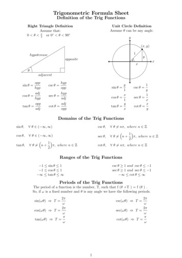
MQ-WSERIESTriple Beam TrigonometricArea Reflective Photoelectric SensorsVery accurate detection by triple beam triangulation sensing method in a compact package.Environmental resistanceImmersion protected construction(equivalent to IEC IP67)High speed detection: Max. 2 msLight-ON/Dark-ON output is wireselectable.Operating voltage of 12 to 24 V DCAdjuster and IndicatorsDistance adjustment dial(Comply with EMC directive MQ-W-EM type only)* OriginalMQ-W3 typeMW-W20 typeSensorOperationIndicator LEDDistance adjustment dialFEATURESAccurate detection regardless ofcolor, material, or shape of objectsArea reflective type sensor can detectwhite or black object at the same distance. In case of diffuse reflective type,it is difficult to detect objects of variouscolor with the same sensitivity setting.MQ-W area reflective type sensor isuseful for such a case.No-miss operation regardless ofback-groundsArea reflective type sensor does notdetect objects beyond the set range.Resistant to lens surface soilingArea reflective type sensor detects thedistance by the angle, not the intensityof received light. Even if the lens surface is soiled by dust or any powderymaterial, there is a little variation ofsensing range.MQ-W70 typeAdjustmentindicator LEDAdjustmentindicator LEDOperationIndicator LEDSENSING RANGESSensing range (m ft.)0.03 .0980.2 .6560.7 2.297MQ-W3 typesMQ-W20 typesMQ-W70 typesPRODUCT TYPEDetection methodRangeRated operating voltage Control outputNPN0.03 m .098 ft.PNPTriple beam areareflective type12 to 24 V DCNPN0.2 m .656 ft.PNP0.7 m 2.297 ft.NPNPNPLight sourcePart number*1 CE typesInfrared LEDMQ-W3A-DC12-24VMQ-W3A-DC12-24VEMRed LEDMQ-W3AR-DC12-24VMQ-W3AR-DC12-24VEMInfrared LEDMQ-W3C-DC12-24VMQ-W3C-DC12-24VEMRed 24VMQ-W20A-DC12-24VEMInfrared LEDRed LEDInfrared LEDRed LEDInfrared LEDMQ-W20AR-DC12-24V VEM*1 These suffix EM types conform to CE. These types have the grounding connection inside of 4V MQ-W20CR-DC12-24VEM
MQ-WSPECIFICATIONS1) Ratings12 to 24 V DCRated operating voltageOperating sideRated current consumptionLoad side30 mA or less (excluding load)100 mA or lessOutput current capacity2) PerformanceDetection principleTriple beam triangulation sensing methodDetection methodArea reflective typeTypeAmplifier selfcontained DC MQ-W3CR-DC12-24VPart numberSensing rangeDetectable distanceStandard -24V0.03 m .098 ft.0.2 m .656 ft.0.7 m 2.297 ft.0.02 to 0.04 m .066 to .131 ft.0.04 to 0.2 m .131 to .656 ft.0.2 to 0.7 m .656 to 2.297 ft.White drawing paper1 1 cm .394 .394 inchWhite drawing paper2 2 cm .787 .787 inchWhite drawing paper7.5 7.5 cm 2.953 2.953 inchDetectable targetOpaque, translucentHysteresis10% or less the set rangeOperating voltage rangeResponse time (freq.)Initial insulation resistanceInitial breakdown voltageVibration resistanceShock resistance9.6 to 30 V DC ripple (P-P) included2 ms or less (250 times per second or less)Min. 20 MΩ between a lead wire and external housing (at 500 V DC)Between a lead wire and external housing: 500 Vrms for 1 min10 to 55 Hz (1 cycle/min), double amplitude 1.5 mm .059 inch (2 h each on 3 axes)980 m/s2 {approx. 100 G} (6 times each on 3 axes)Protective constructionUsable ambientlight level20% or less of the set rangeDiecast case immersion protected (equivalent to IEC IP67)Incandescent lamp10,000 lux or lessSunlight30,000 lux or lessAmbient temperatureAmbient humidity–25 to 55 C –13 to 131 F (non-icing condition)Max. 85% RH (non-condensing condition)Storage temperatureIndicatorLight source–25 to 55 C –13 to 131 FOperation indicator: Red LED ON with light entryAdjustment indicator: Red LED ON with sufficient volume of lightsInfrared LED/Red LED (R is added to the suffix of W3(20)A(C) in the part No.)Note: Unless otherwise specified, the measurement conditions comprise rated operating voltage, power supply by battery, 20 C 68 F ambienttemperature, standard target and 200 lux or less illuminance on the receiver surface.3) Output circuit diagramNPN Output typePNP Output type03/2003181
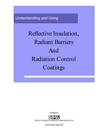
MQ-WDATA1. Operating range characteristics30.09820.066For 40 mm .131 ft.Moving directionStandard target(white drawing paper10 10 mm .394 .394 inch)For 30 mm .098 ft.For 20 mm .066 ft.Operatingdistance (mm)(ft.)40.131MQ-W70 typesOperatingdistance (mm)(ft.)MQ-W20 typesOperatingdistance(mm)(ft.)MQ-W3 types200 For 200 mm .656 ft.6566001.969150 For 150 mm .492 ft.492 Moving directionStandard target(white drawing paper 20 10020 mm .787 .787 inch).328For 100 mm .328 ft.4001.312200.65650.164 For 50 mm .164 ft.1010.394 5 0 5 .394.197.197 Operating range (mm)(inch)1010.394 5 0 5 .394.197.197 Operating range (mm)(inch)For 700 mm 2.297 ft.For 500 mm 1.641 ft.Moving directionStandard target(white drawing paper 75 75 mm 2.953 2.953 inch)For 300 mm .984 ft.1010.394 5 0 5 .394.197.197Operating range (mm)(inch)2. Projector beam diameter characteristicsLight beam diameter is determined as the region where the amount of light is decreased to 1/e2 (e]2.72) when the largest amount of light isassumed as 1.MQ-W3 typesMQ-W20 typesMQ-W70 types2.5 dia. 2.3 dia. 4.0 dia. (mm.098.091.157inch)0020.06630.09823.0 dia. 33.0 dia. 39.0 dia. (mm.9061.2991.535inch)6.7 dia. 6.9 dia. 7.4 dia. 8.3 dia. (mm.264.272.291.327inch)50.16440 (mm ft.).131100.328150.492200 (mm ft.).6560300.9895001.641700 (mm ft.)2.2873 Detectable target characteristicsMQ-W20 typesStandard target(white drawing paper 10 10 mm.394 .394 inch)Distance setting 30 mm.098 ft.30.098MQ-W70 types7002.297200.656Distance setting 200 mm.656 ft.Standard target(white drawing paper 20 20 mm.787 .787 inch)Distance setting 100 mm.328 ft.100.3280Distance setting 40 mm.131 ft.0100100.1550.015Target size (mm2 inch2)6001.969Distance setting 700 mm2.297 ft.Standard target(white drawing paper 75 75 mm2.953 2.953 inch)5001.641Distance setting 400 mm1.312 ft.4001.312300.984Distance setting 200 mm.656 ft.200.656Distance setting 20 mm.066 ft.20.066Distance range (mm ft.)Distance setting 40 mm.131 ft.40.131Distance range (mm ft.)Distance range (mm ft.)MQ-W3 types100.328010010000.1551.55Target size (mm2 inch2)1,0001.5510,00015.5Target size (mm2 inch2)4. Material characteristicsFormer pruductCorrugatedcartonTriple beam type (MQ-W20A)Veneer panelBlack rubberBlack frostedfinishCopper cladprinted circuitboard AluminumpanelMirror100200300400500600.328 .656 .984 1.132 1.641 1.969Distance range (mm ft.) : Impossible182WhitedrawingpaperMQ-W20 typesCondition: Target (40 60 mm 1.575 2.362inch), natural shapeGlossy target Semi-glossy target Non-glossy targetWhite drawingpaperMQ-W3 typesCondition: Target (40 60 mm 1.575 2.362inch), natural shapeGlossy target Semi-glossy target Non-glossy targetComparision between MQ-W20A and former productCondition: Target (40 60 mm 1.575 2.362 inch),target assumed as natural shapeFor the former product (diffuse reflective type),depending upon the object material, the operatingrange varied greatly, but for the triple beam typethere a little variation.BlackdrawingpaperVeneer panelCorrugatedpaperBlack rubberCopper cladprinted circuitboardWhite acrylicBlue acrylicMirror10.03320.06630.098Distance range (mm rVeneer panelCorrugatedpaperBlack rubberCopper cladprinted circuitboardWhite acrylicBlue acrylicMirror50100150.164.328.492Distance range (mm ft.)200.656
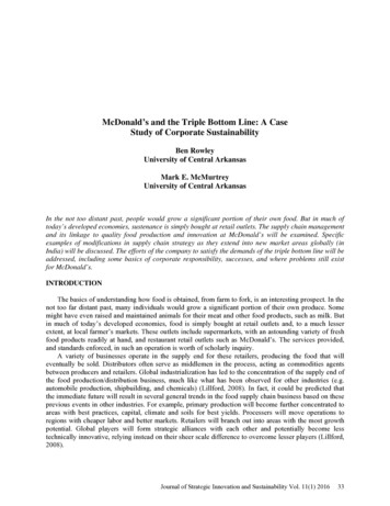
MQ-WDIMENSIONSOutline dimensionsmm inch1. MQ-W3 typesDimensions with the mounting bracket**attachedAdjustment indicator LED12.6 12.2.496 .4804.2 DIA.1654.4Distance adjustment dialOperation indicator LED.1733.33.3.130 25.4 0.2 .1302-M4 (P 0.6) tapped1 inch1M.S.:* M4 or #66.3 .039.248321.26025.4 0.21 inch6.3.24811.7.4613.3.130000 42, 8.772. MQ-W20 types12.6 12.2.496 .4802.2.0876.3.2484.424.4 .173(1 inch)44.81.76424.94510.9.4294.157 1.4.0554.2 DIA.165Distance adjustment dialOperation indicator LED(17)10.7 (.669).4214.4.1733.325.4 0.2 .130 2-M4 (P 0.6) tapped1 inchM.S.:* M4 or #67.3.2872.2.0876.3.2484.424.4 .173(1 inch)7.5.29525.4 0.27.51 inch.295 321.26010.5.4133.3.13044.81.76424.94510.9.429000 42, 8.773. MQ-W70 typesOutline dimensions4.157 1.4.055General tolerance: 0.5 .020Dimensions with the mounting bracket**attached4.2 DIA.165Distance adjustment dial1.0394 16.6.654.15725.41 inchAdjustment indicator LED18.6 18.2.732 .7173.5.138General tolerance: 0.5 .020Dimensions with the mounting bracket**attachedAdjustment indicator LED1.0397.3.2874 16.6.157 .65425.41 inchOutline dimensions3.3.130(17)10.7 (.669).42145 0.21-49/64Operation indicator LED3.5.1384.4.1732-M4 (P 0.6) tappedM.S.:* M4 or #613.51245.01.772(22)12.7 (.866).5004.1574.44.5 DIA.177.1739.18.144.358.319(1-3/4 inch)5213 2.047 45 .138000 42, 8.772412.4 .945.48817.4.68536.61.441451-49/64*M.S.: mounting screw1.6.063General tolerance: 0.5 .020**The mounting bracket is enclosed in the inner carton.CONNECTING DIAGRAMMake connection to B side with pink wire forLight ONMake connection to v side with pink wire forDark ONNote: When switching a power source, makeground connection to the frame ground terminal or to the ground terminal. This will assuremore stable operation.03/2003Operating conditionOutput transistorWith lightintercepted ONCommon useWith lightentering ONOperationindicator LEDLights with light entering183
MQ-WOPERATING PRINCIPLESDetection principle of new triple beam area reflective series Optical triangulation sensing methodThe light beam projected by the LED,passing through the condensing lens ofthe light projector, is applied to the surface of the target to be detected. Onepart of the diffused reflected light rayspasses through the light receiver lensproducing a spot on the position sensitive device. When the detectable targetis at a position A that is at a compara-tively near distance as shown in Fig. 1,a spot is produced at (a). When the target is at a position B that is far, a spotis produced at (b). Accordingly, if anyspot position on the position sensitivedevice is detected, the distance to thetarget can be determined. This is theprinciple of optical triangulation rangemeasurement.Fig. 1 Optical triangulation rangemeasurement methodOther examples of this method arethe automatic focusing and camerarange measurement systems. Triple beam type range sensing principleThe MQ photoelectric sensor areareflective type has adapted this opticaltriangulation range measurement principle, but in order to improve the reliability of the detection of the sensor, amore elaborate method has beendevised. First, light receivers are positioned symmetrically on either side ofthe axis of the light projector, composing a triple beam arrangement. Asshown in Fig. 2, when the movingdetectable target is at the edge of theprojected light beam, the spot reflectedfrom the target is at a location differentfrom the point where the spot is produced when the beam is completelyintercepted, generating a range measurement difference of X, but withthe triple beam composition, the symmetrically arranged position sensitivedevice (2) has a spot produced conversely at a – X difference position,and by means of averaging both rangemeasurement signals, the correct rangemeasurement can be made. Thisresults in significantly improvedrepeatability and background suppression.Fig. 2 Triple beam range measurement methodBy averaging the range measurement signals of the 2 light receivingsystems, the range measurementdifference is cancelled. Optical system of the triple beam photoelectric sensorIn the MQ photoelectric sensor areareflective type, it is necessary to givespecial consideration to the lens. Inorder to improve the precision, anaspherical lens, having limited sphericaland coma aberration, is used.In addition, as shown in Fig. 4, a photodiode having 2 output terminals is used.By comparing the output currents fromthe 2 PSDs, there is no relationship tothe level of the incident light. Thus, theratio of reflection from the detectabletarget exerts no influence and therange measurement and detection canbe interpreted accuracy.Fig. 3 Light beam trace of the lens(a) is a spherical lens, and (b) is theaspherical lens. Because there is noaberration in (b), range measurement precision is high.Fig. 4 PSD (position sensitivedevice) constructionBy making a calculation of the ratioof I1 and I2, the light spot positioncan be detected. Operating principle of area reflective methodThe operation of the MQ photoelectricsensor area reflective type is explainedin Fig. 5. After the output from the 2PSD elements is added, the I/V value isconverted and the logarithm determined. By subtraction, the distance signal in (I1/I2) is obtained. This can beoptionally set, and with the distanceadjustment control, comparison with theproduced value can be made to detectwhether the target is or is not within thedistance range.Fig. 5 Signal processing circuit block diagram18403/2003
MQ-WCAUTIONSThese products are notsafety sensors and arenot designed or intendedto be used to protect lifeand prevent bodily injuryor property damage.1. Ambient environment1) Use within the range of ambienttemperature of –25 to 55 C –13 to 131 F.2) Use within a range of 9.6 V to 30 VDC (ripple P-P included) for operatingvoltage.3) Use with an ambient light level at thelight receiving surface of less than10,000 lux for incandescent lamp andless than 30,000 lux for sunlight.4) Use a surge absorber as the internalcircuit may be damaged if externalsurge voltage exceeds 500 V[ (1.2 50) µs of single polarity fullwave voltage].5) Avoid using in a location with highconcentrations of steam, dust, or corrosive gas.6) The sensor is of immersion protectedtype, but this does not mean that it canbe used in water o
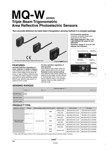
MQ-W3 type MW-W20 type Distance adjustment dial Adjustment indicator LED Adjustment indicator LED Operation Indicator LED MQ-W70 type Distance adjustment dial Very accurate detection by triple beam triangulation sensing method in a compact package. FEATURES Accurate detection regardless of color, material, or shape of objects Area reflective type sensor can detect white or black object at the .