Transcription
Numerical Modelling of I-Beam Jib Crane with LocalStresses in Wheel Supporting Flanges - Influence ofHoisting SpeedNumerički model I-bočne prednje dizalice s lokalnimsilama na podupirajuće šarke na kotačićima – Utjecajbrzine podizanjaTomasz HaniszewskiDamian GąskaFaculty of TransportSilesian University of TechnologyPolande-mail: tomasz.haniszewski@polsl.pl,Faculty of TransportSilesian University of TechnologyPolande-mail: damian.gaska@polsl.plSummaryThis article presents an approach of numerical modelling of I-beam crane jib, withusing the finite element method particularly the most loaded elements at differentspeeds. One of the possible methods for use in the design process of hoistingdynamics modelling and its effects on the load-carrying structure for the marinejib crane is shown. For proper modelling, the impact of the load and hoistingspeed on the load-carrying structure jib, dynamics simulations of hoisting the loadusing Matlab-Simulink software were carried out and in the field of finite elementmethod. To carry out such a simulation, hybrid calculations had to be applied,where the response from the phenomenological model based on solving a systemof differential equations of motion in Matlab-Simulink was used to stimulate thecrane I-beam jib during the FEM simulation, which permits to determine dynamicproperties of the load-carrying structure for two example different hoisting speeds.The basic strength parameters for a typical light marine jib crane, obtained in thecase of static calculations and using the proposed approach between the twocomputing environments were compared.SažetakOvaj članak predstavlja određeni pristup numeričkom modelu I-bočne prednje dizalicekoristeći se metodom ograničenoga elementa, a posebno najčešće ukrcavanihelemenata prema različitim brzinama. Prikazana je jedna od mogućih metodauporabe pri predviđanju procesa modeliranja, dinamike podizanja i njezinih utjecajana strukturu prijevoza tereta za pomorsku dizalicu. Za pravilno modeliranje izvršenje utjecaj opterećenja i brzine podizanja na nosivu strukturu dizalice, te simulacijadinamike podizanja tereta korištenjem Matlab-Simulnik softvera, a sve unutar okviraograničene metode. Kako bi se izvršila takva simulacija, morale su se primijeniti hibridnekalkulacije. Upotrebljen je odgovor na fenomenološki utemeljenom modelu baziran narješavanju sustava diferencijalnih jednadžbi gibanja prema Matlab-Simulnik modelu,kako bi se simuliralo I-bočnu prednju dizalicu za vrijeme FEM simulacije koja dopuštaodređivanje dinamičke osobitosti strukture opterećenja za dva primjera različitih brzinapodizanja. Uspoređeni su osnovni parametri čvrstoće za tipičnu pomorsku dizalicu,dobiveni statističkim izračunima i korištenjem predloženog računalno osmišljenogpristupa.DOI 10.17818/NM/2017/1.2UDK 621.87:656.61629.5:621.87Original scientific paper / Izvorni znanstveni radPaper accepted / Rukopis primljen: 25. 4. 2016.KEY WORDSI-BeamLocal StressImplicitDynamicHoisting ProcessHoisting Speed.KLJUČNE RIJEČII-Beamlokalne sileimplicitnidinamičkiproces podizanjabrzina podizanja1. INTRODUCTION/UvodCranes with girders or jibs in the construction of I-beam arewidely used in industry, during handling, assembly and lightmanufacturing. They provide good value and costs comparedto operating parameters. The advantages of such structuresare primarily light weight, the simplicity of design and ease ofinstallation, low price, the possibility of suspending any hoist.Despite the lower mass, compared with box or truss jibs orgirders, they are slenderer and therefore not suitable for largecrane span or radius [12, 14]. In addition to the drawbacks of“Naše more” 64(1)/2017., pp. 7-13these devices it should also be included roadway wear andproblems with its regeneration and the presence of additionalstress on the lower flange of the hoist wheels [1, 8, 10, 11, 13, 19].Most of these disadvantages do not occur in the case ofI-beam jib cranes used in marinas and yacht harbours, whosemission is to hoist and lower the water boats and yachts.The manifold applications of slewing jib cranes in marinas,boatbuilding, or shipyards are almost unlimited. Post mountedjib cranes are a very space-saving solution for ships to be7
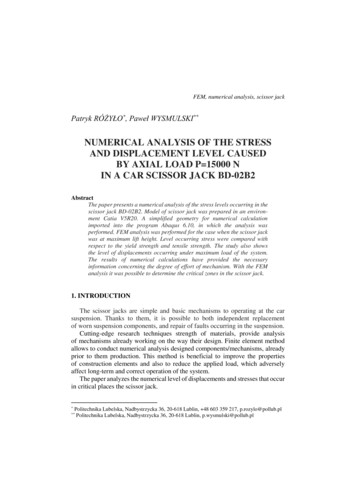
a)b)c)Figure 1 A typical form of jib crane constructions with the arm in the form of I-beam:Slika 1. Tipičan oblik konstrukcije bočne dizalice u obliku Ia) Post-mounted jib crane with 1 hoisting point (single jib with hoisting frame) b) Post-mounted jib crane with 4 independentlycontrollable hoisting points [21] c) Post-mounted jib crane with 4 independently controllable hoisting points and counterweight [22]a) Naknadno montirana dizalica s 1 točkom podizanja (jedan krak s okvirom za podizanje b) Naknadno montirana dizalica sa 4 točkekoje mogu kontrolirati podizanje (21) c) Naknadno montirana dizalica sa 4 neovisno kontrolirane točke i kontra opterećenjem (22)lifted out of the water. Such jib cranes normally do not requirelarge radiuses and load capacities and their class [16] are low.Therefore, it is popular to produce their jibs in the constructionof I-beam. In this case, instead of winches, hoists are used easy to use lifting devices (usually movable), whose mountingstructure is very simple. There are three main types of jib craneload-carrying structure construction used in small ports andyacht marinas: with a counterweight or without, with onehoisting point (single jib), using in many cases a hoisting frameor with 4 independently controllable hoisting points withoutthe need of hoisting frame, and with brackets or without it.An advantage of construction with 4 independentlycontrollable hoisting points is that each arm can separately lift aquarter of the total lifting weight and the front cross beam can bemoved forward and backward. Another major advantage of thistype of jib crane is that yachts with standing mast are possibleto hoist. Counterweight or supports are used to increase thestability of the crane and to maximize load-capacity, height oflift or travel. There are also combinations of the aforementionedtypes. Crane radius of such structures is usually small and donot exceed several meters. Already radius of several meters isenough for launching and hoisting the majority of yachts andsmall boats. Load capacities that are offered by manufacturersreach up to 100 t, but in most cases, 20 t is sufficient even forrelatively large vessels. There can be used chain or rope electricor hydraulic hoists. A typical example of different types of postmounted jib cranes with I-beam jibs is presented in Fig. 1.For all cranes, their primary task is hoisting and transportationof goods over short distances. For both of these movements(in most cases running simultaneously) a substantial dynamicimpact on their structure is made, causing the formationof vibration [8, 9]. It is a negative phenomenon during alloperations of the crane and has a negative impact on all ofits strength and movement parameters [10, 11]. In the designphase of each crane, the load-carrying structure must, therefore,be modeled the hoisting of the unrestrained grounded load.Simplified arrangements for such modeling (providing readymade templates and guidelines) give national and internationalstandards. Modeling of hoisting phenomenon, either in ISO andEN [12-14], is based on the use of dynamic factor, which functionis to “increase” the value of a static force acting on the structureand achieve an effect of quasi-dynamics. Theoretical illustrationof this situation in accordance with standard EN13001-2 isshown in Fig. 2.The value of such coefficient is calculated with a more orless accurate empirical formulas. It is, however, permissible,to use the numerical methods. An important element of theanalytical approach that is present in European and worldFigure 2 Influence of dynamics on generated hoisting force value: a) the behavior of the load, b) the dynamic force [12] where:mhg – force, ϕ2 – dynamic coefficient, Vh – hoisting speed, mH – load massSlika 2. Utjecaj dinamičnosti na proizvedenu vrijednost sile podizanja a) ponašanje tereta b) dinamička sila (12) gdje je: mhg sila, ϕ2 dinamički koeficijent, Vh – brzina podizanja, mH - masa tereta8T. Haniszewski and D. Gąska: Numerical Modelling of I-beam.
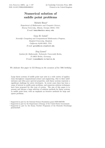
Figure 3 Model dimensions: a) general geometric data of I-beam jib, b) general geometric data of traversing hoist, c) postmounted jibSlika 3. Dimenzije modela: a) općeniti geometrijski podaci I-nosača, b) općeniti geometrijski podaci o poprečnom dizanju, c) naknadnopostavljeni krakstandardization [15-17] is also a suitable model of hoistingmechanism. The hoisting class (determined on the basis of thedynamic characteristics of the drive mechanism) determinesthe appropriate design parameters to calculate the dynamicfactor for hoisting an unrestrained grounded load.Transportation using cranes demands high safety [20],therefore in case of different speeds, there is a need of dynamicmodels creation, that includes effects of failures or human errorslike sudden brake or lifting cargo with not pre-strained rope.This allows the study of the structure behavior and particularlythe most loaded elements at different speeds. Therefore, theanalyzed value of the deflection and stress important from thispoint of view, is defined in the lower flange of I-beam jib, as themost loaded structure element.crane, prepared on the basis of the technical documentation.With analyzing the structure using FEM, it can bedetermined the basic data like stress, form, and frequencyof natural vibration or deflection due to its own weight, loadand boundary conditions. In the case of FEM, difficulties arisewhen it is necessary to enforce modelling caused by a movingtruck or hoisting loads from the ground. Therefore, in the caseof analysis of complex movements in FEM modelling becomesinsufficient [5, 7, 12]. The shown methodology proposes usinghybrid approach involving the coupling of two models - FEMand the phenomenological one.In the case of using the hybrid method, as mentioned in theintroduction, there was a need to create two models, FEA andphenomenological model of a jib crane. For the research, a FEMmodel was used that was shown in the work [6].N, mm, MPa system of units was applied, therefore resultsof stresses are in MPa and displacements in mm are shown.The load – carrying structure was made from S355 steel wherethe limit design stress for sheets thickness 63 mm is 305 MPa[17]. There were used mainly standardized general purposefour-node shell element S4R, eight-node brick element withreduced integration C3D8R and two-node beam element B31from Abaqus Software Documentation [18]. Model presented inFigure 4 and 5 consists of 112750 elements and 138298 nodes.2. NUMERICAL MODEL OF I-BEAM GIRDER /Numerički model I-bočne dizaliceThe model for numerical calculations of the jib crane was madefor HEB 300 I-beam with a length of 6 m and mounted hoistwith a hoisting capacity of 5 t and wheel span of 0.795 m. Theused construction had a bearing on the pillar and two bracketsmounted on it. The model was loaded in the end position of thehoist on the jib. Geometrical relationships are shown in Fig. 3.Table 1 shows the general characteristics of the tested jibTable 1 Characteristics of experimental craneTablica 1. Karakteristike eksperimentalne dizaliceDescriptionhoisting capacitycrane radius“Naše more” 64(1)/2017., pp. 7-13Dimension[kg]Value50006L[m]Hp max[m]5hoistinghoist travelvhvjw[m/s][m/s]1st 0.11, 2nd 0.220.34supply voltageU[V]380hoisting heightoperating speedSymbolQ9
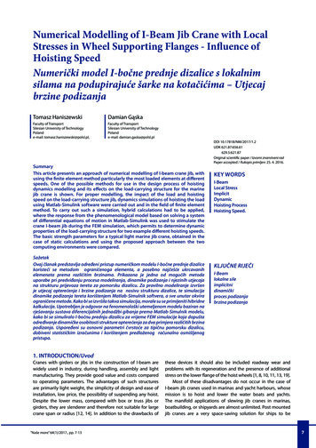
Figure 4 FEM model: a) c) d) mesh, b) geometrySlika 4 FEM model: a) c) d) mreža, b) geometrijaThe boundary conditions were established throughreference points, which tied with the construction bonds typeMPC Beam (figure 5). The design of the jib is divided into twoparts - one surface-type and a solid type (in order to reduce thecomputation time and take the possibility to calculation stressstate between wheels and beam). These parts are connectedto one another by bonding a shell to solid coupling, whichconnects the lateral surface of the solid model with the edgesurface of the shell model. Loads were applied by force to thewheel axle hoist through means of a kinematic coupling. Loadof the I-beam jib lower flange was implemented by means ofa surface to surface contact for the wheel - upper flange planeand near the side plane with a coefficient of friction in thevalue of 0,15. Extraction art was modelled by using beam typeelement and was connected to beam and also the mast which ismade by using shell elements.Figure 6 Simplified phenomenological model of examined jibcrane, which includes Kelvin-Voigt model of wire ropeSlika 6. Pojednostavljeni fenomenološki model ispitivane kranskedizalice koja uključuje Kevin-Voigt žičani modelFigure 5 FEM model and reference pointsSlika 5. FEM model i referentne točkeCalculations were made using the cluster IBM BladeCenterHS21. The solver was Abaqus Implicit according to MNiSW/IBMBC HS21/PŚląska/026/2014 grant.3. PHENOMENOLOGICAL MODEL OF JIB CRANESSTRUCTURE / Fenomenološki model struktureprednje dizaliceA dynamic model of the jib crane with the hoisting mechanism isshown in Figure 6. This model includes in its structure elementssuch as a jib, rope drum, wire rope, and ground.10On the basis of the concept of generalized coordinates, andphenomenological model shown in Figure 6, the equations ofmotion can be written as second type Lagrange equations [2,3, 5, 7, 12]:(1)where:t – time, qj – generalized displacement, q̇ j – generalizedvelocity, n – number of degrees of freedom, Fj – generalizedforce, Ek – kinetic energy, Ep – potential energy, ER – energydissipation function.This approach allows to obtain the differential equations ofmotion in the form of kinetic energy of the system:T. Haniszewski and D. Gąska: Numerical Modelling of I-beam.
(2)(7)where:m1 – reduced mass of jib, m2 – mass of load, m3 – mass of therope drum, J3 – mass moment of inertia of t
jib crane is shown. For proper modelling, the impact of the load and hoisting speed on the load-carrying structure jib, dynamics simulations of hoisting the load using Matlab-Simulink software were carried out and in the field of finite element method. To carry out such a simulation, hybrid calculations