Transcription
HSSLRFDBeam LoadTables
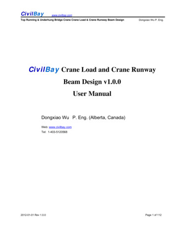
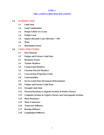
HSS Manufacturing MethodsThe transformation of steel strip into hollow structural sections (HSS) is the result of operations including forming, welding and sizing. Currently threemethods are being used in North America for the manufacture of HSS. These methods, including two ERW methods and an SAW method, are describedbelow. Both ERW methods meet ASTM A 500 and CSA G-40.21 requirements for the manufacture of HSS, and the ERW sizes included in this publicationmay be produced to either standard. The SAW method is not included as a manufacturing process in the ASTM or CSA specification. SAW sizes listed in thispublication can be specified to meet desired physical and dimensional criteria of ASTM A500 and CSA G-40.215 6 7Electric Resistance Welding (ERW) ProcessIn the tube mill, flat steel strip (1) is formed continuously around itslongitudinal axis to produce a round tube. This is done by moving thestrip through a progressive set of rolls (2-6). The strip edges (7) areheated by either high frequency induction or contact welding and thenforged together by weld rolls to create a continuous longitudinal weldwithout the addition of filler metal. The weld seam (8) is then cooledand processed through a set of sizing/shaping rolls which cold-form itinto a round (9), square (10) or rectangular (11) section.432189Form-Square Weld-Square (ERW) ProcessIn the weld mill, driven forming dies progressively shape the flat strip(1) by forming the top two corners (2) of the square or rectangular tubein the initial forming station. Subsequent stations form the bottom twocorners (3) of the shape. No cold working of the sides of the shape isperformed, and the shape’s seam is welded by high-frequency contactswhen the tube is near its final shape and size. The welded tube (4) iscooled and then driven through a series of sizing stations which qualifiesthe tube’s final dimensions.101141233Submerged Arc Weld (SAW) ProcessTwo identical pieces of flat strip (1) are placed in a press brake andformed into two identical halves (2) of a finished tube size. A backup baris tack welded to each leg of one of the half-sections (3). The two halfsections are fitted together toe-to-toe (4) and welded by the submergedarc process to complete the square or rectangular section (5).251234211
STI/HSS Member CompaniesAtlas Tube, Inc.200 Clark Street, P.O. Box 970Harrow, Ontario N0R 1G0Telephone: (519) 738-3541(800) 265-6912Fax: (519) 738-3537IPSCO Tubulars Inc.P.O. Box 18, 2011 7th AvenueCamanche, IA 52730Telephone: (563) 242-0000(800) 950-4772Fax: (563) 242-9137Bull Moose Tube Company1819 Clarkson Road, Suite 100Chesterfield, MO 63017Telephone: (636) 537-2600(800) 325-4467Fax: (636) 537-5848LTV Copperweld1855 East 122nd StreetChicago, IL 60633Telephone: (800) 733-5683Fax: (773) 646-6128(In Canada)14 Holtby AvenueBrampton, OntarioCanada L6X 2M3Telephone: (905) 451-2400(800) 268-3005Fax: (905) 840-4716Eugene Welding CompanyP.O. Box 249Marysville, MI 48040Telephone: (810) 364-7421(800) 336-3926Fax: (810) 364-4347Hanna Steel CorporationP.O. Box 558, Fairfield, AL 35064Telephone: (205) 780-1111(800) 633-8252Fax: (205) 783-8296Hannibal Industries, Inc.P.O. Box 58814, 3851 Santa Fe Ave.Los Angeles, CA 90058Telephone: (323) 588-4261Fax: (323) 589-5640Independence Tube Corporation6226 W. 74th StreetChicago, IL 60638-6196Telephone: (708) 496-0380(800) 376-6000Fax: (708) 563-1950OF NORTH AMERICAMaverick Tube Corporation16401 Swingley Ridge Road,Suite 700Chesterfield, MO 63017Telephone: (314) 733-1600(800) 840-8823Fax: (314) 733-1677Novamerican Steel Inc.2175 Hymus BoulevardDorval, Quebec, Canada H9P 1J8Telephone: (514) 335-6682(800) 361-1496Fax: (514) 683-5285(In United States)600 Dean Sievres PlaceMorrisville, PA 19067Telephone: (215) 295-8813Fax: (215) 295-8798Productos Laminadosde Monterrey, SA de CVHeadquarters & Monterrey PlantAve. Lazaro Cardenas 1525 Pte.Col. Nino ArtilleroMonterrey, N.L. Mexico C.P. 64280Telephone: (8) 351-1625(8) 351-1070Fax: (8) 351-0322(U.S. Office)Prolamsa, Inc.12603 SW Freeway, Suite 521Stafford, TX 77477Telephone: (281) 494-0900Fax: (281) 494-0990Valmont Industries(Structural Tube Division)P.O. Box 2620Tulsa, OK 74101Telephone: (918) 583-5881(800) 331-3002Fax: (918) 585-1927Vest, Incorporated6023 Alcoa AvenueLos Angeles, CA 90058Telephone: (323) 581-8823(800) 421-6370Fax: (323) 581-3465Welded Tube of Canada Limited111 Rayette RoadConcord, Ontario,Canada L4K 2E9Telephone: (905) 669-1111(800) 565-8823Fax: (905) 738-4070
ForewordLoad and Resistance Factor Design (LRFD) beam load tables are presented for rectangular and square Hollow StructuralSections (HSS) manufactured by the electric resistance welding (ERW) method and the submerged arc welding (SAW) method.Maximum factored uniform loads for simple laterally supported beams have been calculated in accordance with the AISC"Specification for the Design of Steel Hollow Structural Sections – April 15, 1997". This Specification is a supplement to theAISC "Load and Resistance Factor Design Specification for Structural Steel Buildings – December 1, 1993". The factoreduniform loads are based upon section property data for HSS that were recalculated in 1996 to account for more precise manufacturing methods. Revised section property data for HSS is published in "Hollow Structural Sections – Dimensions and SectionProperties" available from the Steel Tube Institute of North America.Tables are presented for two specified minimum yield point steels; Fy 46 ksi and Fy 50 ksi. The tabulated factored uniformloads for HSS sizes produced by the ERW and SAW methods are presented in separate tables.The factored uniform loads, in kips, are based upon the flexural design strength specified in the "HSS Specification". Factoreduniform loads are also included for HSS defined as slender-element cross-sections. These sections are identified in the tableswith an asterisk ( * ) immediately following the design wall thickness parameter in the heading and a double asterisk ( ** )immediately following the effective section modulus, Seff, in the Properties section. The foot weight of the HSS beam is included in the tabulated loads and must be deducted to determine the net load that the beam will support. It is assumed that theloading is applied in the plane of the minor axis and that the HSS beam deflects vertically in the plane of bending only.Refer to Part 4 – Beam and Girder Design, of the AISC 2nd Edition "Manual of Steel Construction – Load & Resistance factorDesign" for a discussion of the design strength of beams. Symbols used in these tables follow those used in the AISC "Manual".Table of ContentsPageHow to use the Beam Load Tables .5Beam Load TablesRectangular HSS (ERW)Fy 46 ksi.6Square HSS (ERW)Fy 46 ksi.28Rectangular HSS (ERW)Fy 50 ksi .36Square HSS (ERW)Fy 50 ksi.58Rectangular HSS (SAW)Fy 46 ksi.66Square HSS (SAW)Fy 46 ksi.68Rectangular HSS (SAW)Fy 50 ksi.70Square HSS (SAW)Fy 50 ksi.764
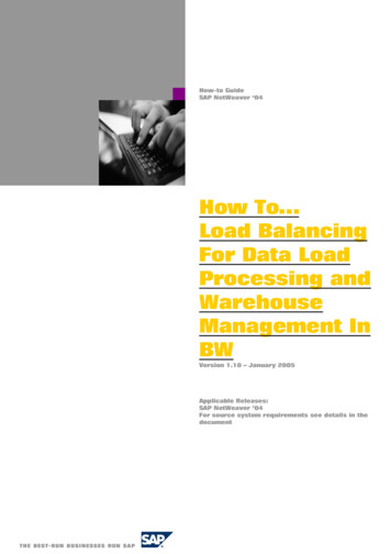
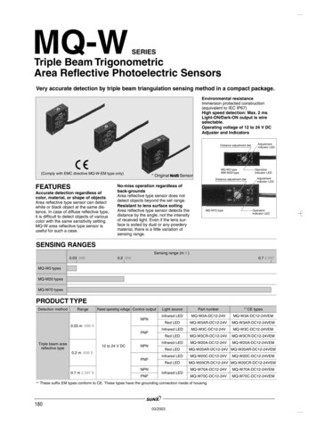
How To Use The Beam Load TablesExample 1A simply supported 20 in. x 12 in. x 3/8 in. ERW HSS beam ofFy 46 ksi (ASTM A500 Gr. B) spans 22 feet. The beam is laterallybraced for its entire length. Determine the uniform load capacity forloading in the plane of the minor axis.Enter the Fy 46 load table for the HSS20x12x3/8 (page 6). Readacross the row at the span equal to 22 feet and note that the maximumfactored uniform load is equal to 167 kips. Note that this includes theweight of the HSS beam.Example 2Select the lightest 8-inch deep, simply supported ERW HSS beam ofFy 50 ksi (ASTM A500 Gr. C) to span 8 feet and support a maximumfactored uniform load of 52 kips (includes the estimated weight of theHSS beam). The beam is laterally supported for its entire length.Enter the Fy 50 ksi load tables for the 8-in. deep rectangular and8 in. deep square HSS. Note that the maximum factored uniform loadcapacity for a:HSS8x8x1/4HSS8x8x3/16(25.82 lbs./ft.) 70 kips 52 kips o.k.(19.63 lbs./ft.) 46 kips 52 kips not goodHSS8x6x1/4HSS8x6x3/16(22.42 lbs./ft.) 63 kips 52 kips o.k.(17.08 lbs./ft.) 43 kips 52 kips not goodHSS8x4x5/16HSS8x4x1/4(23.34 lbs./ft.) 60 kips 52 kips o.k.(19.02 lbs./ft.) 50 kips 52 kips not goodHSS8x3x5/16HSS8x3x1/4(21.21 lbs./ft.) 52 kips 52 kips o.k.(17.32 lbs./ft.) 43 kips 52 kips not goodSelect: HSS8x3x5/16 (weight 21.21 lbs. per ft.)The information presented in this publication has been prepared inaccordance with recognized engineering principles and is forgeneral information only.While it is believed to be accurate, thisinformation should not be used or relied upon for any specificapplication without competent professional examination andverification of its accuracy, suitability, and applicability by alicensed professional engineer, designer, or architect.The publicationof the material contained herein is not intended as a representationor warranty on the part of The Steel Tube Institute of North Americaor of any other person named herein, that this information issuitable for any general or particular use or of freedom frominfringement of any patent or patents. Anyone making use of thisinformation assumes all liability arising from such use.Caution must be exercised when relying upon other specificationsand codes developed by other bodies and incorporated by referenceherein since such material may be modified or amended from timeto time subsequent to the printing of this edition.The Institute bearsno responsibility for such material other than to refer to it andincorporate it by reference at the time of the initial publication ofthis edition.
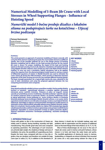
Fy 46LRFD BeamsRectangular HSSyxyERWMaximum Factored Uniform Loads in Kips for Beams Laterally Supported20 x 12Nominal SizeWall Thickness1/2Weight Per Foot103.30Design Wall 751911121314155/865.87110.360.291*0.58120 x 41/23/889.6868.310.4650.349Fy 46 1494342Ix, 90367027105110420032302720317024602090Effective length KL in feet34520 x 85/16xPROPERTIESΦvVn, (kips)ΦbWc, (kip-ft)98.2**92692.6Load above heavy horizontal line is limited by design shear strength.* Section contains slender compression element; i.e. λ λr.** Effective section modulus, Seff, calculated in accordance with AISC “HSS Specification" Section 6
Fy 46LRFD BeamsRectangular HSSyxyERWMaximum Factored Uniform Loads in Kips for Beams Laterally Supported18 x 6Nominal SizeWall Thickness5/81/23/8Weight Per Foot93.3476.0758.10Design Wall Thickness0.58116 x 868.310.4650.349Fy 46 ksi16 x 049434587837269555347453836Ix, tive length KL in feet345PROPERTIESΦvVn, (kips)ΦbWc, 04370277231373026601990Load above heavy horizontal line is limited by design shear strength.* Section contains slender compression element; i.e. λ λr.** Effective section modulus, Seff, calculated in accordance with AISC “HSS Specification" Section 029302270192082.156.469.4
Fy 46LRFD BeamsRectangular HSSyxyERWMaximum Factored Uniform Loads in Kips for Beams Laterally Supported16 x 4Nominal Sizex14 x 10Wall Thickness1/23/85/165/81/23/85/161/4Weight Per 373635455360308380310Effective length KL in feetDesign Wall Thickness0.4650.3490.2910.5810.465Fy 46 31251191121072122232425PROPERTIESIx, in.4Sx,in.3in.3Zx,ΦvVn, (kips)ΦbWc, 20216221301660141033102730211016501170Load above heavy horizontal line is limited by design shear strength.* Section contains slender compression element; i.e. λ λr.** Effective section modulus, Seff, calculated in accordance with AISC “HSS Specification" Section 5.1(b).8
Fy 46LRFD BeamsRectangular HSSyxyERWMaximum Factored Uniform Loads in Kips for Beams Laterally Supported14 x 6Nominal SizeWall Thickness5/81/23/8Weight Per Foot76.3362.4647.90Effective length KL in feet14 x 90.5810.4650.3490.2910.2330.1740.581Fy 46 82930949187848231323334357977747270Design Wall OPERTIESIx, in.4Sx,in.3in.3Zx,ΦvVn, (kips)ΦbWc, 0109030.195.8754Load above heavy horizontal line is limited by design shear 3719.525.395.8698
Fy 46LRFD BeamsRectangular HSSyxyERWMaximum Factored Uniform Loads in Kips for Beams Laterally Supported12 x 10Nominal Size12 x 8Wall Thickness1/23/85/161/45/81/23/8Weight Per Foot69.2753.0044.6036.0376.3362.4647.90Effective length KL in 72829308481787572Design Wall Thicknessx0.5810.465Fy 46 383940PROPERTIESIx, in.4Sx,in.3Zx, in.3ΦvVn, (kips)ΦbWc, 52270188014601240934Load above heavy horizontal line is limited by design shear strength.* Section contains slender compression element; i.e. λ λr.** Effective section modulus, Seff, calculated in accordance with AISC “HSS Specification" Section 5.1(b).1014021.8**27.896.7602
Fy 46LRFD BeamsRectangular HSSyxyERWMaximum Factored Uniform Loads in Kips for Beams Laterally Supported12 x 6Nominal SizeWall Thickness5/81/23/8Weight Per Foot67.8255.6642.79Effective length KL in feetDesign Wall 3176789103162712372111901112131415x12 x 12105100959993888379777369656221222
weight of the HSS beam. Example 2 Select the lightest 8-inch deep, simply supported ERW HSS beam of Fy 50 ksi (ASTM A500 Gr. C) to span 8 feet and support a maximum factored uniform load of 52 kips (includes the estimated weight of the HSS beam). The be