Transcription
ISO Milling 1Principles of programming2Drive commandsSINUMERIKSINUMERIK 840D sl / 828DISO Milling3Motion commands4Additional functionsAAbbreviationsBG code tableProgramming ManualCData descriptionDData listsEInterruptsValid forControlSINUMERIK 840D sl / 840DE slSINUMERIK 828DSoftware VersionCNC software 4.502/20126FC5398-7BP40-3BA0
Legal informationWarning notice systemThis manual contains notices you have to observe in order to ensure your personal safety, as well as to preventdamage to property. The notices referring to your personal safety are highlighted in the manual by a safety alertsymbol, notices referring only to property damage have no safety alert symbol. These notices shown below aregraded according to the degree of danger.DANGERindicates that death or severe personal injury will result if proper precautions are not taken.WARNINGindicates that death or severe personal injury may result if proper precautions are not taken.CAUTIONindicates that minor personal injury can result if proper precautions are not taken.NOTICEindicates that property damage can result if proper precautions are not taken.If more than one degree of danger is present, the warning notice representing the highest degree of danger willbe used. A notice warning of injury to persons with a safety alert symbol may also include a warning relating toproperty damage.Qualified PersonnelThe product/system described in this documentation may be operated only by personnel qualified for the specifictask in accordance with the relevant documentation, in particular its warning notices and safety instructions.Qualified personnel are those who, based on their training and experience, are capable of identifying risks andavoiding potential hazards when working with these products/systems.Proper use of Siemens productsNote the following:WARNINGSiemens products may only be used for the applications described in the catalog and in the relevant technicaldocumentation. If products and components from other manufacturers are used, these must be recommendedor approved by Siemens. Proper transport, storage, installation, assembly, commissioning, operation andmaintenance are required to ensure that the products operate safely and without any problems. The permissibleambient conditions must be complied with. The information in the relevant documentation must be observed.TrademarksAll names identified by are registered trademarks of Siemens AG. The remaining trademarks in this publicationmay be trademarks whose use by third parties for their own purposes could violate the rights of the owner.Disclaimer of LiabilityWe have reviewed the contents of this publication to ensure consistency with the hardware and softwaredescribed. Since variance cannot be precluded entirely, we cannot guarantee full consistency. However, theinformation in this publication is reviewed regularly and any necessary corrections are included in subsequenteditions.Siemens AGIndustry SectorPostfach 48 4890026 NÜRNBERGGERMANYOrder number: 6FC5398-7BP40-3BA0 10/2012 Technical data subject to changeCopyright Siemens AG 2001 - 2012.All rights reserved
Table of contents123Principles of programming . uctory comments .7Siemens mode .7ISO dialect mode .7Switching between the modes .8Display of the G code.8Maximum number of axes/axis identifiers.9Decimal point programming .9Comments.10Skip ions for the feed .12Rapid traverse.12Path feed (F function) .12Fixed feedrates F0 to F9.14Linear feed (G94).16Inverse-time feed (G93) .17Revolutional feedrate (G95).17Drive commands. ion commands.19Rapid traverse (G00) .19Linear interpolation (G01) .21Circular interpolation (G02, G03) .22Contour definition programming and addition of chamfers or radiuses .25Helical interpolation (G02, G03).27Involute interpolation (G02.2, G03.2).28Cylindrical interpolation (G07.1).292.22.2.12.2.22.2.3Reference point approach with G functions.33Reference point approach with intermediate point (G28) .33Checking the reference position (G27) .35Reference point approach with reference point selection (G30) .36Motion commands . 3.1.10The coordinate system.37Machine coordinate systems (G53) .38Workpiece coordinate system (G92) .39Resetting the tool coordinate system (G92.1) .40Selection of a workpiece coordinate system.40Writing work offset/tool offsets (G10).41Local coordinate system (G52) .43Selection of the plane (G17, G18, G19) .44Parallel axes (G17, G18, G19).45Rotation of the coordinate system (G68, G69) .463D rotation G68/G69.48ISO MillingProgramming Manual, 02/2012, 6FC5398-7BP40-3BA03
Table of contents43.23.2.13.2.23.2.33.2.4Defining the input modes of the coordinate values. 49Absolute/incremental dimensioning (G90, G91) . 49Inch/metric input (G20, G21). 50Scaling (G50, G51) . 51Programmable mirroring (G50.1, G51.1) . 543.33.3.1Time-controlled commands. 56Dwell time (G04) . 563.43.4.13.4.23.4.33.4.4Tool offset functions . 57Tool offset data memory . 57Tool length compensation (G43, G44, G49) . 57Cutter radius compensation (G40, G41, G42) . 60Collision detection . 643.53.5.13.5.23.5.33.5.43.5.53.5.63.5.7S-, T-, M- and B functions . 68Spindle function (S function) . 68Tool function. 68Additional function (M function). 68M functions of spindle control. 70M functions for subroutine calls . 70Macro call via M function. 71M functions . 723.63.6.13.6.23.6.3Controlling the feedrate. 73Automatic corner override G62 . 73Compressor in the ISO dialect mode . 75Exact stop (G09, G61), Continuous-path mode (G64), tapping (G63) . 76Additional functions. 4.1.104.1.114.1.124.1.134.1.144.1.154.1.16Program supporting functions . 77Fixed drilling cycles . 77Deep hole drilling cycle with chip breakage (G73). 82Fine drilling cycle (G76) . 85Drilling cycle, preboring (G81) . 88Drilling cycle, preboring (G82) . 90Deep hole drilling cycle with chip removal (G83) . 92Drilling cycle (G85). 94Boring cycle (G86) . 96Boring cycle, reverse countersinking (G87) . 98Drilling cycle (G89), return with G01 . 101Cycle "Tapping without compensating chuck" (G84) . 103"Drilling a left-hand thread without compensating chuck" cycle (G74) . 106Left or right tapping cycle (G84 or G74). 109Deselection of a fixed cycle (G80) . 112Program example with a tool length compensation and fixed cycles . 113Multiple-start threads with G33 . 1154.24.2.14.2.24.2.3Programmable data input (G10) . 116Changing the tool offset value. 116Working area limitation (G22, G23) . 116M function for calling subroutines (M98, M99) . 1184.3Eight-digit program number. 1194.4Polar coordinates (G15, G16) . 121ISO Milling4Programming Manual, 02/2012, 6FC5398-7BP40-3BA0
Table of contents4.5Polar coordinates interpolation (G12.1, G13.1) .1224.64.6.14.6.24.6.34.6.44.6.5Measuring functions.124Rapid lift with G10.6.124Measuring with "delete distance-to-go" (G31) .125Measuring with G31, P1 - P4 .127Interrupt program with M96, M97.128"Tool life control" function .1304.74.7.14.7.24.7.3Macro programs .131Differences with subroutines.131Macro program call (G65, G66, G67) .131Macro call via G function.1384.84.8.14.8.2Special functions.141Contour repetition (G72.1, G72.2) .141Switchover modes for DryRun and skip levels .144AAbbreviations. 145BG code table . 153CData description. 157DEC.1General machine data.157C.2Channel-specific machine data.170C.3Axis-specific setting data .185C.4Channel-specific setting data.186C.5Channel-specific cycle machine data .188Data lists. 191D.1Machine data.191D.2Setting data .193D.3Variables .194Interrupts . 197Glossary . 199Index. 225ISO MillingProgramming Manual, 02/2012, 6FC5398-7BP40-3BA05
Table of contentsISO Milling6Programming Manual, 02/2012, 6FC5398-7BP40-3BA0
Principles of programming1.1Introductory comments1.1.1Siemens mode1The following conditions are valid in the Siemens mode: The default of the G commands can be defined for each channel via the machine data20150 MC GCODE RESET VALUES. No language commands from the ISO dialects can be programmed in the Siemens mode.1.1.2ISO dialect modeThe following conditions are valid in the active ISO dialect mode: The ISO dialect mode can be set with machine data as the default setting of controlsystem. The control system reboots by default in the ISO dialect mode subsequently. Only G functions from the ISO dialect can be programmed; the programming of SiemensG functions is not possible in the ISO Mode. Mixing of ISO dialect and Siemens language in the same NC block is not possible. Switching between ISO Dialect M and ISO Dialect T with a G command is not possible. Subroutines that are programmed in the Siemens mode can be called. If Siemens functions are to be used, one must first switch to the Siemens mode.ISO MillingProgramming Manual, 02/2012, 6FC5398-7BP40-3BA07
Principles of programming1.1 Introductory comments1.1.3Switching between the modesThe following G functions can be used to switch between the Siemens mode and the ISOdialect mode: G290 - Siemens NC programming language active G291 - ISO Dialect NC Programming language activeThe active tool, the tool offsets and work offsets are not influenced by the switchover.G290 and G291 must be programmed alone in an NC block.1.1.4Display of the G codeThe G code is displayed in the same language (Siemens or ISO Dialect) as the relevantcurrent block. If the display of the blocks is suppressed with DISPLOF, the G codes continueto be displayed in the language in which the active block is displayed.ExampleThe G functions of the ISO dialect mode are used to call the Siemens standard cycles. To dothis, DISPLOF is programmed at the start of the relevant cycle; this way the G functions thatare programmed in the ISO dialect language continue to be displayed.PROC CYCLE328 SAVE DISPLOFN10 .N99 RETProcedureThe Siemens shell cycles are called via main programs. The Siemens mode is selectedautomatically by calling the shell cycle.With DISPLOF, the block display is frozen on calling the cycle; the display of the G codecontinues in the ISO Mode.The G codes that were changed in the shell cycle, are reset to their original status at the endof the cycle with the "SAVE" attribute.ISO Milling8Programming Manual, 02/2012, 6FC5398-7BP40-3BA0
Principles of programming1.1 Introductory comments1.1.5Maximum number of axes/axis identifiersThe maximum number of axes in the ISO dialect mode is 9. The axis identifiers for the firstthree axes are defined permanently with X, Y and Z. All other axes can be identified with theletters A, B, C, U, V and W.1.1.6Decimal point programmingIn the ISO dialect mode, there are two notations for evaluating programmed values withoutdecimal point: Pocket calculator notationValues without decimal points are interpreted as mm, inch or degree. Standard notationValues without decimal point are multiplied by a conversion factor.The setting is done over MD10884 MN EXTERN FLOATINGPOINT PROG.There are two different conversion factors, IS-B and IS-C. This weighting is related to theaddresses X Y Z U V W A B C I J K Q R and F.Example:Linear axis in mm: X 100.5corresponds to a value with decimal point: 100.5 mm X 1000– Pocket calculator notation: 1,000 mm– Standard notation:IS-B: 1,000* 0.001 1 mmIS-C: 1,000* 0.0001 0.1 mmISO MillingProgramming Manual, 02/2012, 6FC5398-7BP40-3BA09
Principles of programming1.1 Introductory commentsISO dialect millingTable 1- 1Different conversion factors for IS-B and IS-CAddressUnitIS-BIS-CLinear axismm0.0010.0001inch0.00010.00001Rotary axisDegree0.0010.0001F feed G94 (mm/inch per .010.01F feed G95 (mm/inch per min.)F thread leadC chamferR radius, G10 toolcorrQI, J, K IPO nch0.00010.00001mm0.0010.0001inch0.00010.00001G04 X or Us0.0010.001A angle contour definitionDegree0.0010.0001G74, G84 tapping cycles MC EXTERN FUNCTION MASKBit8 0 F as feed such as G94, G95Bit8 1 F as thread lead1.1.7CommentsIn the ISO dialect mode, brackets are interpreted as comment signs. In the Siemens mode,";" is interpreted as comment. To simplify matters, an ";" is also understood as comment inthe ISO dialect mode.If the comment start sign '(' is used inside a comment again, the comment is ended only if allthe open brackets are closed again.Example:N5 (comment) X100 Y100N10 (comment(comment)) X100 Y100N15 (comment(comment) X100) Y100X100 Y100 is executed in block N5 and N10, but only Y100 in block N15, because the firstbracket is closed only after X100. Everything up to that point is interpreted as comment.ISO Milling10Programming Manual, 02/2012, 6FC5398-7BP40-3BA0
Principles of programming1.1 Introductory comments1.1.8Skip blockThe sign of skipping or suppression of blocks "/" can be used at any convenient position in ablock, i.e. even in the middle of the block. If the programmed block skip level is active on thedate of the compilation, the block is not compiled from this point up to the end of the block.An active block skip level has the same effect as a block end.Example:N5 G00 X100. /3 YY100 -- Alarm 12080 "Syntax error"N5 G00 X100. /3 YY100 -- no alarm, if block skip level 3 is activeBlock skip signs within a comment are not interpreted as block skip signsExample:N5 G00 X100. ( /3 Part1 ) Y100;the Y axis is traversed even when the block skip level 3 is activeThe block skip levels /1 to /9 can be active. Block skip values 1 and 9 lead to alarm 14060"Impermissible skip level for differential block skip".The function is mapped to the existing Siemens skip levels. Unlike the ISO Dialect original,"/" and "/1" are separate skip levels that must also be activated separately.NoteThe "0" in "/0" can be omitted.ISO MillingProgramming Manual, 02/2012, 6FC5398-7BP40-3BA011
Principles of programming1.2 Preconditions for the feed1.2Preconditions for the feedThe following Section describes the feed function with which the feedrate (covered path perminute or per rotation) of a cutting tool is defined.1.2.1Rapid traverseRapid traverse is used for positioning (G00) as well as for manual traverse with rapidtraverse (JOG). In rapid traverse, each axis is traversed with the rapid traverse rate set forthe individual axes. The rapid traversing rate is defined by the machine manufacturer and itis specified by the machine data for the individual axes. As the axes traverse independentlyof each other, each axis reaches its target point at a different time. Hence, the resulting toolpath is generally not a straight line.1.2.2Path feed (F function)NoteUnless something else is specified, the unit "mm/min" always stands for feedrate of thecutting tool in this documentation.The feed with which a tool should be traversed in linear interpolation (G01) or circularinterpolation (G02, G03) is designated with the address character "F".The feed of the cutting tool in "mm/min" is specified after the address character "F".The permissible range of F values is specified in the documentation of the machinemanufacturer.Possibly, the feed is limited by the servo system and the mechanical system in the upwarddirection. The maximum feed is set in the machine data and limited to the value definedthere before an overshoot.The path feed is generally composed of the individual speed components of all geometryaxes participating in the movement and refers to the cutter center (see the two followingfigures).ISO Milling12Programming Manual, 02/2012, 6FC5398-7BP40-3BA0
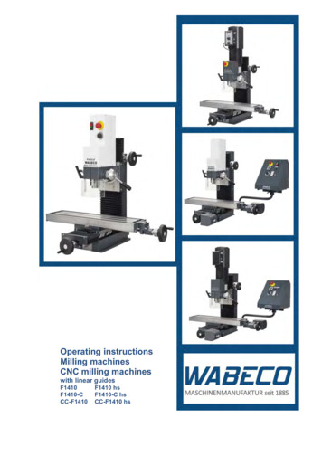
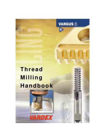
Principles of programming1.2 Preconditions for the feed3URJUDPPLQJ H[DPSOH ZLWK WKH IROORZLQJ SURJUDP* ,QFUHPHQWDO GLPHQVLRQLQJ* ; ) 3DWK YHORFLW\ LQWDQJHQWLDO GLUHFWLRQ PP PLQ PP PLQ PP PLQ ;Figure 1-1Linear interpolation with 2 axes3URJUDPPLQJ H[DPSOH ZLWK WKH IROORZLQJ SURJUDP* ,QFUHPHQWDO GLPHQVLRQLQJ* ; , ) &HQWHU SRLQW PP PLQ)\ )[ ;Figure 1-2Circular interpolation with 2 axesIn 3D interpolation, the feed of the resulting straight lines programmed with F are maintainedin the space.ISO MillingProgramming Manual, 02/2012, 6FC5398-7BP40-3BA013
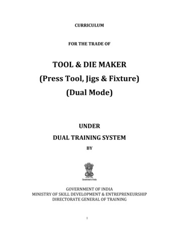
Principles of programming1.2 Preconditions for the feed3URJUDPPLQJ H[DPSOH ZLWKWKH IROORZLQJ SURJUDP* ; ) (QG SRLQW PP PLQ6WDUW SRLQW ; Figure 1-3Feed in case of 3D interpolationNoteIf "F0" is programmed and the function "Fixed feedrate" is not active, then the Alarm 14800"Programmed path velocity less than or equal to zero" is output.1.2.3Fixed feedrates F0 to F9Activate feed valuesTen different feed values pre-set via setting data can be activated with F0 to F9. To activatethe rapid traverse rate with F0, the corresponding speed must be entered in the setting data42160 SC EXTERN FIXED FEEDRATE F1 F9[0].The feed values for F0 to F9 are entered in the setting data as real values. An evaluation ofthe input values is not undertaken.The function is activated via the machine data 22920 MC EXTERN FIXED FEEDRATE F1 ON. If the machine data is set to FALSE, F1 - F9 isinterpreted as normal feed programming, e.g. F2 2 mm/min, F0 0 mm/min.If the machine data TRUE, the feed values for F0 - F9 are fetched from the setting data42160 SC EXTERN FIXED FEEDRATE F1 F9[ ]. If the value 0 exists in one of thesetting data, then the corresponding address extension of feed 0 is activated during theprogramming.ISO Milling14Programming Manual, 02/2012, 6FC5398-7BP40-3BA0
Principles of programming1.2 Preconditions for the feedExample SC FIXED FEEDRATE F1 F9[0] 5000 SC FIXED FEEDRATE F1 F9[1] 1000 SC FIXED FEEDRATE F1 F9[2] 500N10 X10 Y10 Z10 F0 G94;Approach position at 5000 mm/minN20 G01 X150 Y30 F1;Feed 1000 mm/min activeN30 Z0 F2;Position approached at 500 mm/minN40 Z10 F0;Approach position at 5000 mm/minTable 1- 2S
Principles of programming 1.1 Introductory comments ISO Milling 8 Programming Manual, 02/2012, 6FC5398-7BP40-3BA0 1.1.3 Switching between the modes The following G functions can be used to switch between the Siemens mode and the ISO dialect mode: G290 - Siemens NC programming language active