Transcription
Haas Factory OutletA Division of Productivity IncHaas LatheProgrammingRevised 8/4/2022 JP
This Manual is the Property of Productivity Inc.It may not be reproduced or disseminated without the express written permissionof Productivity Inc. The content must not be altered, nor have the Productivityname removed from the materials. This training manual is a guide for theoperation of the Machine Tool.The Operator is responsible for following Safety Procedures as outlined by theirInstructor or the Manufacturers Specification. Downloading and/or other use ofthis manual does not certify the completion of the Training Course. This manual isfor reference only.For more information on Additional Training Opportunitiesor our Classroom Schedule,Contact Productivity Inc. 763.476.8600 (800)328-3272 Toll FreeVisit us on the Web: www.productivity.comTo obtain permissions contact: trainingmn@productivity.comNote: Some of the content, images and screen shots included in this manual are taken fromHaas manuals, controllers and web information with permission from Haas Automation Inc.2800 Sturgis Road Oxnard CA 93030-89332
Haas Lathe Programming Training ManualTable of ContentsHAAS LATHE PROGRAMMING TRAINING MANUAL TABLE OF CONTENTS .3INTRODUCTION .5THE COORDINATE SYSTEM .6MACHINE HOME .7ABSOLUTE AND INCREMENTAL POSITIONING .9CARTESIAN COORDINATE X, Z GRID . 10TYPICAL LATHE PART . 10LATHE PART PROJECTED ON LATHE X Z GRID . 11TYPICAL LATHE PART . 12PROGRAMMING . 16PROGRAM FORMAT. 17DEFINITIONS WITHIN THE FORMAT . 18ALPHABETICAL ADDRESS CODES . 19PREPARATORY FUNCTIONS (G CODES) . 23MISCELLANEOUS FUNCTIONS (M CODES) . 25MACHINE DEFAULTS. 26LATHE PROGRAMMING . 27MACHINING CYCLES FOR THE LATHE . 30DRILLING, TAPPING AND BORING CANNED CYCLES . 30MACHINE CYCLES FOR TURNING AND GROOVING . 31LINEAR/CIRCULAR MOVEMENT-CREATING TOOL PATHS . 32INTERPOLATION COMMANDS . 34LINEAR INTERPOLATION EXERCISE . 35CIRCULAR INTERPOLATION COMMANDS. 36CIRCULAR INTERPOLATION MOTION EXERCISES . 41CIRCULAR INTERPOLATION EXERCISE . 433
MANUALLY PROGRAMMING TOOL NOSE COMPENSATION . 44CALCULATING COMPENSATION FOR A RADIUS ON YOUR PART . 44RADIUS CALCULATION . 45EXTERNAL RADIUS CALCULATION . 46INTERNAL RADIUS CALCULATION . 46CALCULATING COMPENSATION FOR “AN ANGLE” ON YOUR PART . 50TOOL NOSE RADIUS CALCULATION DIAGRAM . 51TOOL NOSE COMPENSATION – TAPER CALCULATION . 52MISCELLANEOUS G CODES . 61REFERENCE POINT DEFINITION AND RETURN . 61SPINDLE SPEED COMMANDS . 62WORK COORDINATE SYSTEM SELECTION . 63FEED COMMAND FUNCTIONS. 63TOOL NOSE COMPENSATION G CODES . 64TOOL NOSE COMPENSATION PROGRAMMING. 66TOOL NOSE COMPENSATION CONCEPTS . 68IMAGINARY TOOL TIP AND DIRECTION . 69USING TOOL NOSE COMPENSATION. 70CANNED CYCLES AND ADDITIONAL G CODES. 78TOOL NOSE COMPENSATION IN CANNED CYCLES . 81TYPE 1 DETAILS . 90TYPE II DETAILS . 90FACE, TURN AND CUT-OFF EXERCISE . 96TYPE I DETAILS . 99G76THREAD CUTTING CYCLE, MULTIPLE PASS . 113THREAD PROGRAMMING EXERCISE . 117DRILLING, BORING AND TAPPING CANNED CYCLES . 119EXERCISE . 120CYLINDER ROD THREAD LATHE PROGRAM EXERCISE . 121CANNED CYCLES FOR DRILLING AND TAPPING . 122M CODE DETAILED DESCRIPTION . 1374
IntroductionWelcome to Productivity, Inc., your local Haas Factory Outlet (H.F.O.) for the Haas Lathe ProgrammingClass. This class is intended to give a basic understanding of the set-up and operation of a Haas TurningCenter.In an "NC" (Numerically Controlled) machine, the tool is controlled by a code system that enables it tobe operated with minimal supervision and with a great deal of repeatability. "CNC" (ComputerizedNumerical Control) is the same type of operating system, with the exception that a computer monitorsthe machine tool.The same principles used in operating a manual machine are used in programming an NC or CNCMachine. The main difference is that instead of cranking handles to position a slide to a certain point,the dimension is stored in the memory of the machine control once. The control will then move themachine to these positions each time the program is run.The operation of the SL-Series Turning Center requires that a part program be designed, written, andentered into the memory of the control. There are several options for getting these programs to thecontrol. RS-232 (serial port with a computer), 3.5” Floppy Disk, Ethernet / Networking/ and USB are allviable ways to transmit and receive programs.In order to operate and program a CNC controlled machine, a basic understanding of machiningpractices and a working knowledge of math is necessary. It is also important to become familiar with thecontrol console and the placement of the keys, switches, displays, etc., that are pertinent to theoperation of the machine.At Productivity, we have two classes that pertain to Haas Turning Centers: Lathe Operator and LatheProgramming.We have two classes to fill the different needs of our customers as not all people that require trainingrequire programming training.This manual can be used as both an operator's manual and as a programmer's manual. It is intended togive a basic understanding of CNC programming and its applications. It is not intended as an in-depthstudy of all ranges of machine use, but as an overview of common and potential situations facing CNCprogrammers. Much more training and information is necessary before attempting to program on themachine.Revised CK 5/9/14; Rev CK 310175
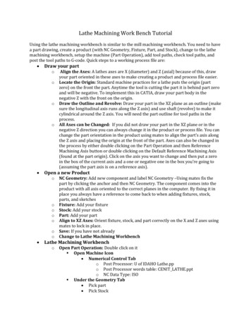
The Coordinate SystemAll CNC machines move tools to specific locations described by coordinate systems. With lathes thecoordinate system can be simply described as two number lines that intersect.The illustration below shows two number lines that intersect at a location described as reference zeroor Absolute Zero.With lathes the vertical number line is called the X-axis. The horizontal number line is called the Z-axis.The movements of the lathe are described by the illustration below. The up and down motion or X-axiscorresponds to the vertical number line. The Z-axis or side to side motion corresponds to the horizontalnumber line. The intersection of the two lines is Absolute Zero.When programming lathes X0 is always the centerline of the part you are working on. It is the Xposition on the Z axis that the part rotates around. Z0 normally is the front finished face of the part.6
Machine HomeAt start up all Haas machine tools must be returned to zero or taken to what is called a Home ReferencePosition. A zero return (POWER UP/RESTART) is required when you power on a Haas machine. During azero return all axes are moved to extreme positive locations until limit switches are reached. The reasonthe machine does this is to double check its position with the “Home” switches of the machine.This is crucial to the operation and function of a CNC machine as all of our programs, locations offixtures and tooling are based off of machine home. At home position the machine coordinates are X0,Z0. It would not be easy or convenient to write a program using machine coordinates. Insteadprograms are written with values that would correspond to dimensions found on prints. To do this asecondary floating zero point is established using offsets. This floating zero is referred to as the PARTZERO or PART ORIGINAs shown above the centerline of the part becomes (X) zero. Normally the front face of the part isdesignated as Z (zero). The reason being it is easy to access and easier to program. With this scheme thecenterline of the lathe is always the “X” zero. The “Z” zero location will float with the face of differentparts.When we setup a machine, we need to tell the machine the distance different tools at home positionare from the part origin. Each tool is manually touched off the face and diameter and thru keystrokesthe distances from machine zero to the part zero are saved in X and Z register of the Tool Offsets Page.Alternately tools may be set using the tool pre-setter. If the tools are set with a tool pre-setter or otherZ reference point not at the Part Zero a Z Work Shift must be done.A work shift is stored in the Work Offsets Page in the Z value. Several different work offsets may beused. The Z value in the Work Offset page is the distance and direction the Part Zero is from the Zreference or tool pre-setter touch off position. Normally X values are always zero. If the face of the partis used to determine the Tool Offsets then the value for Z in the Work Offset page will be zero.7
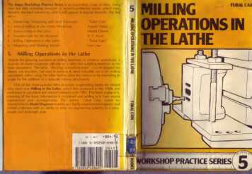
X AxisThe diagram above shows the operator’s view of X and Z grid standing in front of the lathe. At theintersection of the X and Z axis is the Part Zero or Reference Point. Note there is four differentquadrants with different positive and values for X and Z.An ST-20 lathe has travel distance of 9.3” in the X and 21” in the Z. Haas lathes have a negative oneinch (-1”) travel beyond the centerline of the Z Axis spindle. Note that most of the X values in a partprogram are going to be positive. Normally the only negative X value is going to be when you face thepart off past centerline. As the Z zero is normally the face of the part when you are cutting into the partthe Z values will be negative.Note that the X values on the Haas lathe are in diameters. Therefore an X move from centerline or X0to X1.0 will only be moving the machine along the X axis 0.5 inch in the positive direction.8
Absolute and Incremental PositioningBy using WORK and TOOL OFFSETS a common point on the part is designated as “PART ZERO”. This issome point on our part that we can physically find. The programmer uses this point as a base to writethe intended movement of the tooling.Programmers normally use the front end of our finish machined part as (Z Zero) and the centerline ofpart as (X Zero).There are two methods used by the programmer to “Steer” our machine.The first is “ABSOLUTE POSITIONING”. Absolute means that X and Z code values are based on the ZEROPOINT on the part. If a diameter of 1.0000 inches is needed, it is input as X1.0000. If the print requiresfacing a shoulder that is 3 inches back from the front of the part, Z-3.0000 in input in the code.The programmer has another tool available to him called “INCREMENTAL POSITIONING”. This ismovement based on where the machine is currently sitting. It is also called point to point programming.If a change of half inch smaller diameter is required of the machine from where it is currently sitting U.5000 is put in the code. If a grooving tool is making a groove that is located ¾” behind a groove that isalready finished, W-.7500 is input.The letters X&Z represent ABSOLUTE POSTIONINGThe letters U&W represent INCREMENTAL POSTIONINGIf you are familiar with the mill programming language, absolute and incremental are handleddifferently for Mills and Lathes. A mill uses G codes (G90 and G91) to go back and forth between thetwo. Whereas a lathe uses the different letters to differentiate them.QUESTION:Why doesn’t a lathe take G90 and G91 like a mill?ANSWER:A lathe has the unique possibility to do Absolute AND Incremental moves AT THE SAME TIME.The programmer can place an ABS. letter and an INC. letter on a line of code together, and is mostcommonly used in making tapers and radius moves.G01 X2.000 W-.25 (Move X in Absolute, Z in Incremental)orG01 U.5000 Z-.5000 (Move X in Incremental, Z in Absolute)9
Cartesian Coordinate X, Z GridTypical Lathe Part10
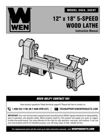
Lathe Part Projected on Lathe X Z GridGive the X and Z coordinates for the part below. Note the X values are diameterson Haas Lathes not radii.XPoint 1Point 2Point 3Point 4Point 5Point 6Point 711Z
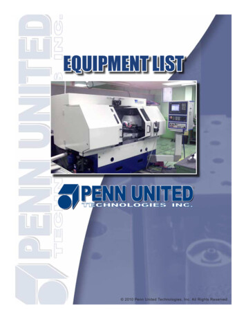
Typical Lathe PartBelow is a typical lathe part sitting in a chuck. Note thefloating zero determined by the programmer.12symbol. It denotes the
Above is the print for the part on previous page. Knowing X and Zcoordinates for key positions below is the first step in programming.Give the X and Z coordinates for the part below. Note the X values arediameters on Haas Lathes not radii.XZPoint 1Point 2Point 3Point 4Point 513
NOTES14
For the different points below calculate X diameters and Z lengths. The values between (parentheses)would be points where the tool is already located, and those points in a program, would not need to bedefined again.XPt 1Pt 2Pt 3Pt 4 ( )Pt 5Pt 6Pt 7 ( )Pt 8Pt 9 ( )Pt 10Pt 11 ( )Pt 12Z( )( )( )NOTE: Exercise taken from SL Series Haas Automation CNC Machine Programming Workbook, Haas Automation Inc., 2800Sturgis Road, Oxnard CA, 93030, page 9, copyright Haas Automation 2004.15
ProgrammingThe definition of a part program for any CNC consists of movements of the tool and speed changes tothe spindle RPM. It also contains auxiliary command functions such as tool changes, coolant on or offcommands, or external M codes commands.Tool movements consist of rapid positioning commands, straight line movement of the tool at acontrolled speed, and movement along an arc.The Haas lathe has two (2) linear axes named X and Z. the X-axis moves the tool turret toward and awayfrom the spindle center line, while the Z axis moves the tool turret along the spindle axis. The machinezero position is where the tool is at the right corner of the work cell farthest away from the spindle axis.Motion in the X-axis will move the table toward the spindle centerline for negative numbers and awayfrom spindle center for positive numbers. Motion in the z-axis will move the tool toward the spindlechuck for negative numbers and away from the chuck for positive numbers.A program is written as a set of instructions given in the order they are to be performed. Theinstructions, if given in English, might look like this:LINE #1 LINE #2 LINE #3 LINE #4 LINE #5 LINE #6 LINE #7 SELECT CUTTING TOOL.TURN THE SPINDLE ON AND SELECT THE RPM.TURN THE COOLANT ON.RAPID TO THE STARTING POSITION OF THE PART.CHOOSE THE PROPER FEED RATE AND MAKE THE CUT(S)TURN OFF THE SPINDLE AND THE COOLANT.RETURN TOOL TO HOLDING POSITION AND SELECT NEXT TOOLand so on. But our machine control understands only these messages when given in machine code.16
Program FormatThere are no positional requirements for a line CNC code. That means the different codes in a programmay be in any order on a line of code. However some standard rules are followed so the code is easierto view. It will also make it easier for the machinist to understand when he runs the part if the programhas a standard level of organization. Some standard rules are followed:X and Z values are positioned in alphabetical order and grouped togetherG and M codes may be placed anywhere on a line but convention is that the G codes come first and theM codes come at the end of the block. This makes sense as the last thing to happen on a line is the Mfunction. The G codes are completed first then the M code is performed on any given line.On Haas machines only one M code is allowed on a block of code.Command codes are first given by a letter then a number. Some codes like X,Z and F require decimalpoints. Others like S and G require an integer (a number with no fractional part).17
Definitions Within the FormatCharacter:A single alphanumeric character value or the “ ” and “-“ sign.Word:A series of characters defining a single command such as “X” displacement or “F”Feed rate. Unique letters are assigned as the first character of a word, and each letterhas either a plus ( ) or minus (-) sign value of numbers.Block:Series of words defining a single instruction. An instruction may consist of a single linearor circular motion, plus additional information such as a feed rate or stop command. Ablock of code is on one single line.Positive Signs: If a number value following the address command letters, such as I, K, R, U, W, X, Z, ispositive, the plus sign need not be programmed. If the number value is negative, itmust be programmed with a minus (-) sign.Leading Zero’s: There is no need to program zeros proceeding a number.Example: G00 (G0) and M01 (M1).Trailing zeros however must be programmed.Example: M30 not M3, G70 or G7.Modal Commands:Once a particular word, such as G, X, Z, F, S, T, and M is programmed, it is notnecessary to repeat the word in the following blocks until a different word orchange of value is required in subsequent blocks of information.Non-Modal Commands: A non-modal command is one that is active only in the program block in whichit is issued. M00 program stop is an example of a non-modal command.Preparatory Functions: “G” codes use the information contained on the line to make the machine tooldo specific operations, such as: Move the tool at rapid traverse.Move the tool at feed rate along a straight line.Move the tool along and arc at a feed rate in a clockwise direction.Move the tool along an arc at a feed rate in a counterclockwise direction.Move the tool through a series of repetitive operations controlled by “fixed cycles”such as, spot drilling, boring, and tapping.Miscellaneous Functions:Sequence Numbers:“M” codes cause an action to occur at the end of the block. Only one MCode is allowed in each block.Sequence numbers are codes N1 through N9999 and are only used tolocate a certain block or line within a CNC program. A program may be inputwithout sequence numbers.18
Alphabetical Address CodesThe following is a list of the Address Codes used in programming the lathe:AFOURTH AXIS ROTARY MOTIONThe A address character is normally used to specify motion for the optional fourth A, axis. It specifies anangle in degrees for the rotary axis. It is always followed by a signed number and up to three fractionaldecimal positions. If no decimal point is entered, the last digit is assumed to be 1/1000 degrees. Thesmallest magnitude is 0.001 degrees, the most negative value is -8380.000, and the largest value is8380.000 degrees.The A axis on the Haas lathe is currently reserved for the tool turret and is hidden to the programmer.The units of rotation indicate tool positions such that 1.000 represents tool #1.BLINEAR B-AXIS MOTIONThe B address character is used to specify absolute motion for the B axis. It specifies a position ordistance along the B axis. It is either in inches with four fractional positions or millimeters with threefractional positions. It is followed by a signed number between -8380.00 and 8380.00. If no decimalpoint is entered, the last digit is assumed to be 1/10000 inches or 1/1000 millimeters.On the Haas lathes the B axis is either travel of the tail stock or sub-spindle.CFIFTH AXIS ROTARY MOTIONThe C address character is used to specify motion for the optional external fifth, C, axis. It specifies anangle in degrees for the rotary axis. It is always followed by a signed number and up to three fractionaldecimal positions. If no decimal point is entered, the last digit is assumed to be 1/1000 degrees. Thesmallest magnitude is 0.001 degrees, the most negative value is -8380.00, and the largest value is8380.00 degrees.DCANNED CYCLE DATAThe D address character is used within several canned macro cycles:In G71 and G72 stock removal cycles D prescribes the depth of cut used for each pass.In G73 D indicates the number of passes to remove a set amount of stock.In G76 multiple pass threading cycle D sets the depth of cut on the first pass.EFEED RATE, 6 PLACE PRECISION (SAME AS F)The E address character is used to select feed rate applied to any interpolating G codes or canned cycles.The unit is in inches per revolution or mm per revolution. Up to six fractional positions can be specified.The default of units/revolution (G99) can be changed to units/minute with G98. For YASNAC and FANUCcontrol compatibility, use the E code when 5 or 6 place precision is desired.19
FFEED RATEThe F address character is used to select feed rate applied to any interpolating G codes or canned cycles.The unit is in inches per revolution or mm per revolution. The default of units/revolution (G99) can bechanged to units/minute with G98. Traditionally, the F code was capable of only 4-fractional positionaccuracy; but on this control you can specify F to six place accuracy. Code E and F are equivalent.GPREPARATORY FUNCTIONS (G CODES)The G address character is used to specify the type of operation to occur in the block containing the Gcode. The G is followed by a two or three digit number between 0 and 255. Each G code defined in thiscontrol is part of a group of G codes. The Group 0 codes are non-modal; that is, they specify a functionapplicable to this block only and do not affect other blocks. The other groups are modal and thespecification of one code in the group cancels the previous code applicable from that group. A modal Gcode applies to all subsequent blocks so those blocks do not need to re-specify the same G code. Morethan one G code can be placed in a block in order to specify all of the setup conditions for an operation.See the following section (Preparatory Functions (G Codes)) for a detailed list of G codes. The G codesare specified in an A/B/C format to show the three different G coding systems. Each system uses adifferent G code for the same function. In this manual, programming is described based on the Asystem, however, Setting 34 (G CODE SYSTEM) can be used to select another system.HNOT USED, OPTIONAL MACRO PARAMETERICANNED CYCLE AND CIRCULAR OPTIONAL DATAThe I address character is used to specify data used for some canned cycles and circular motions. It iseither in inches with four fractional positions or mm with three fractional positions. It is followed by asigned number in inches between -8380.00 and 8380.00 for inches or between -8380.00 and 8380.00 formetric.JCANNED CYCLE AND CIRCULAR OPTIONAL DATAThe J address character is used to specify data used for some canned cycles and circular motions. It isformatted just like the I data.KCANNED CYCLE AND CIRCULAR OPTIONAL DATAThe K address character is used to specify data used for some canned cycles and circular motions. It isformatted just like the I data.LLOOP COUNT FOR REPEATED CYCLESThe L address character is used to specify a repetition count for some canned cycles and auxiliaryfunctions. It is followed by an unsigned number between 0 and 32767.20
MM CODE MISCELLANEOUS FUNCTIONSThe M address character is used to specify an M code for a block. These codes are used to controlmiscellaneous machine functions. Not that only one M code is allowed per block of the CNC programand all M codes are performed at the end of the block.NNUMBER OF BLOCKThe N address character is entirely optional. It can be used to identify or number each block of aprogram. It is followed by a number between 0 and 99999. The M97, M98 and M99 functions mayreference an N line number.OPROGRAM NUMBER PROGRAM NAME PARENTHESISThe O address character is used to identify a program. It is followed by a number between 0 and 99999.A program saved in memory always has a Onnnnn identification in the first block; it cannot be deleted.Altering the O in the first block causes the program to be renamed. A program may have only oneOnnnnn command a colon (:) may be used in the place of O, but is always displayed as “O”. “O”Programs may be deleted by highlighting in the List Program page by using the DEL key or ERASE PROGkey. Up to 500 programs may be stored in the List Program page.PDELAY TIME OR PROGRAM NUMBERThe P address character is used to enter either a time in seconds or a program number for a subroutinecall. If it is used as a time (for a G04 dwell) or a program name (for a M97), the value may be either apositive number without decimal point up to 9999. If it is used as a time, it may be a positive decimalwith fraction between 0.001 and 1000.00.QCANNED CYCLE OPTIONAL DATAThe Q address character is used in canned cycles and is always a positive number in inches/mm between0 and 100.0.RCANNED CYCLE AND CIRCULAR OPTIONAL DATAThe R address character is used in canned cycles and circular interpolation. It is either in inches withfour fractional positions or mm with three fractional positions. It is followed by a signed number ininches between -8380.00 and 8380.00 for
Welcome to Productivity, Inc., your local Haas Factory Outlet (H.F.O.) for the Haas Lathe Programming Class. This class is intended to give a basic understanding of the set-up and operation of a Haas Turning Center. In an "NC" (Numerically Controlled) machine, the tool is controlled by a code system that enables it to .