Transcription
Lathe Machining Work Bench TutorialUsing the lathe machining workbench is similar to the mill machining workbench. You need to havea part drawing, create a product (with NC Geometry, Fixture, Part, and Stock), change to the lathemachining workbench, setup the machine (Part Operation), add tool paths, check tool paths, andpost the tool paths to G-code. Quick steps to a working process file are: Draw your partoooo Open a new Productooooooo Align the Axes: A lathes axes are X (diameter) and Z (axial) because of this, drawyour part oriented in these axes to make creating a product and process file easier.Locate the Origin: Standard machine practices for a lathe puts the origin (partzero) on the front the part. Anytime the tool is cutting the part it is behind part zeroand will be negative. To implement this in CATIA, draw your part body in thenegative Z with the front on the origin.Draw the Outline and Revolve: Draw your part in the XZ plane as an outline (makesure the longitudinal axis runs along the Z axis) and use shaft (revolve) to make itcylindrical around the Z axis. You will need the part outline for tool paths in theprocess.All Axes can be Changed: If you did not draw your part in the XZ plane or in thenegative Z direction you can always change it in the product or process file. You canchange the part orientation in the product using mates to align the part’s axis alongthe Z axis and placing the origin at the front of the part. Axes can also be changed inthe process by either double clicking on the Part Operation and then ReferenceMachining Axis button or double clicking on the Default Reference Machining Axis(found at the part origin). Click on the axis you want to change and then put a zeroin the box of the current axis and a one or negative one in the box you’re going to(assuming the part axis is on a reference axis).NC Geometry: Add new component and label NC Geometry –Using mates fix thepart by clicking the anchor and then NC Geometry. The component comes into theproduct with all axis oriented to the correct planes in the computer. By fixing it inplace you always have a reference to come back to when adding fixtures, stock,parts, and sketchesFixture: Add your fixtureStock: Add your stockPart: Add your partAlign to XZ Axes: Orient fixture, stock, and part correctly on the X and Z axes usingmates to lock in place.Save: If you have not alreadyChange to Lathe Machining WorkbenchLathe Machining WorkbenchoOpen Part Operation: Double click on it Open Machine Icon Numerical Control Tabo Post Processor: U of IDAHO Lathe.ppo Post Processor words table: CENIT LATHE.ppto NC Data Type: ISO Under the Geometry Tab Pick part Pick Stock
oo Pick Fixture Under Position Tab Set Tool Change Point to X largest radius of your part plus at least¼ an inch and Z 6Click on Manufacturing Program Add your tool paths – tool paths are added underneath a highlighted toolpath so they can be inserted at any place in the manufacturing program byhighlighting the path above where you want to add it Check every tab and do not forget to add macros – these can quickly beassessed by click on preview (remember green means good, red needs work,and yellow will usually turn green after clicking preview or Tool Pathreplay) Before posting G-code and running part on the lathe watch the entire video(Sometimes I have only been able to access this from the last tool path butyou should be able to access it from the manufacturing program). For themost part if you see a problem in the video the same problem will occur onthe lathe. Specify Tool Orientation: Make the tool look the same as if on the lathe(found under the tooling tabs) which will most likely require the followingsteps. Invert the tool Commonly used tools are right handed (choose this option undermore ) After every tool add Post-Processor Instructions to get the lathe to move tothe tool change position and stop. The following instructions will move thetool tip to 2 inches from the center axis of the part and 6 inches from theend. If your part is bigger than 2 inches in diameter (X) or your next tool islonger than 6 inches in length (Z) the values will need to be changed. Theseinstructions are: INSERT X2. Z6.make sure to put the decimal after the numberif it is a whole number otherwise it is read as 1/10000 of an inch STOPPost the code: the lathe post is keyed to a specific machine, so if you want needthan 100 lines of code (counted by 10s or N980) use the machine to the left of theinstructor’s machine. To get to the post Right Click on Manufacturing Program Go down to ManufacturingProgram.1 object Select Generate NC Code Interactively In/Out Tab Change location of output file – Make sure to put a .nc after the file name andeach time you execute the program you will have to put a .nc after the filelocation in the output file box if your code does not post check this first Tool Motions The first four boxes should be checked (assuming the lathe acts likethe mill and so far it has been working) Check set rapid at start of operations NC Code Tab Check to make sure U of IDAHO Lathe.pp is selected
Click ExecuteG-Code: Execute generates 6 files in the location you specified. Look for the .nc fileand open it with notepad. You can then read the G-code generated by the program.It should start and end with a % sign. The first line after the % sign should be OXXXXwhere the Xs are your program number. At the end of the program, just before the% sign should be an M30.Run the Part: You can now run your G-Code on the Haas Latheo Tips, Pointers and Recent lessons learnedoooooAn NC program name starts with an O followed by four numbers (example: O0500).To get the proper name in CATIA you have to rename the Part Operation to theprogram number, for example to have the G-code read O0500 change the PartOperation to 500 by right clicking on it and going to properties then change the labelbox to your program numberFor threading the post does not appear to use a canned cycle (this may change withfuture revisions to the post) so under the first tab from the left in a thread turningoperation (Machining Options) and then under the Options tab deselect OutputCycle syntaxUsing a grooving tool if you do not want to clean up a wall select only the bottom ofthe groove.Constant Surface Feet is taken out of the current post. A constant surface speedgives a nicer finish to a part. If you want it you will need to add a G50 S1800followed by a G96 in place of the G97 after each tool by hand. Look in the red Haasbinder behind the control panel the program tab for an example. Remember onceyou do this speed of the machine is in surface feet per minute and not RPM whenentering the spindle speed in the Feeds and Speeds tab of a turning operation. Anexample of a SFPM for mild steel using a high speed steel cutting tool is 60 to 90. AG96 cause the RPM of the spindle to increase as the radial distance between the tooland center line of the spindle decreases (i.e. the diameter of your part becomessmaller).You can add instructions to your G-code using the Post-Processor Instructionsbutton. The instructions are added after the highlighted operation in theManufacturing Program. This is a powerful tool for adding code. It is also necessaryto get proper tool changes. Make sure you add the following lines in a PostProcessor Instructions Dialog box after every tool: INSERT X2. Z6. STOPBasic Lathe Machining Workbench Tutorial (step by step instructions)Two different methods are used to start this tutorial. You can choose to use either of the methodsdescribe. The final part is the same using both methods the difference is either drawing the partfrom scratch or taking a part already drawn and oriented it correctly in the product.1. Get part file from websitea. Save as your own file with a new name if you are going to orient it.2. Choose your methoda. Drawing method: Make sure your part origin and axes are correct go to step 3 fordetailed instruction.b. Orienting method: Go to step 4
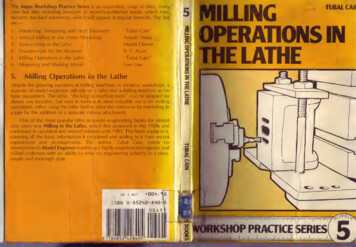
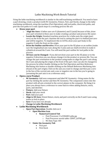
3. Drawing your parta. Open a new part drawingb. Click on sketch and the ZX planec. Starting at the origin draw half the part into the negative Z direction as seen inFigure 1. Don’t forget to add the center line. Copy the dimensions from the drawingon the website.d. Use shaft to revolve the part around the Z axise. Show your sketch by expanding the tree to the sketch then right click and selectHide/Showf. Do not forget to add a ¼ inch hole through the center of the partg. Go to step 4Figure 1. General idea of how to start the part4. Open a New Producta. Rename the producti. Right click on Product go to properties and give it a nameb. Create a new Parti. Right click on Product go to components and click new partc. Rename the new part NC Geometryi. Right click on part just created go to properties and change Part Number to NCGeometryd. Fix NC Geometryi. There are two ways to do this: click on the anchor and then click the name NCGeometry or expand NC Geometry in the tree and click on one of the xyzplanes then click the anchor to fix it (you can and only need to fix one plane)
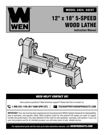
e. Add a Lathe Chuck or fixturei. This is just a part drawing. It can be elaborate or simpleii. A simple cylinder with a hole in the middle will work (example measurementsare is 6” in diameter with a 1” hole in the center and 3.5” thick). Remember todraw the chuck in the ZX plane similar to drawing the part in step 3 and useshaft to rotate it around the Z axis.iii. There are two way to do this:1. Method one: right click on the product, go to components, add newpart, and click No to new origin. Then rename it fixture and expandthe tree to part body. By double clicking on part body you can get tothe sketcher. To get back to the product, double click on the productname.2. Method Two: Draw the chuck in a separate part file and then rightclick on the product, go to components, and add existing part.iv. Use constraints to position the chuck 2” in the negative Z direction see figure 2as an example. Use the offset constraint with the XY plane in NC Geometry andthe XY plane for the chuck.v. A chuck is not required to make a process file but it adds to the tool simulationvideo when checking the tool pathsFigure 2. Location of lathe chuck in the product file
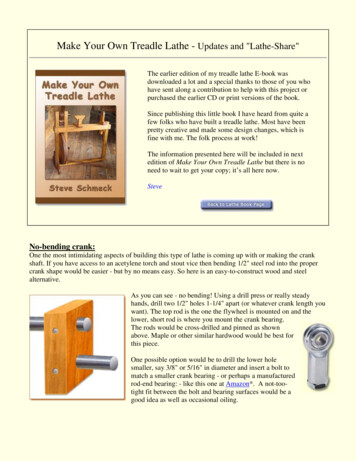
f.Add stocki. Stock dimensions should be 1 inch in diameter and 2.1 inches long for thispart; make sure the center axis of the stock aligns with the Z axis. Draw thesketch with 2 inches in the negative Z and .1 inches in the positive Z. Then useshaft to rotate the part.ii. In order to calculate a tool path you need to have stock. You need your partfully enclosed in the stock. Tool paths are defined off your stock.iii. Rename the part Stockiv. Once your stock is added you can right click on stock in the tree go toproperties and then graphics to change its transparency and colorFigure 3. Stock located in the chuckg. Add your parti. Drawing method: right click product go to existing part and add your partii. Orientation method: right click product go to existing part and add the partprovide.1. Attach the compass to the part and orient it with the central axisalong the z axis2. Make sure the part origin is in the negative Z direction from the NCGeometry origin
3. Make sure the part outline is parallel to the ZX plane (it is easier todo if you unhide the sketch and you need unhidden the process file)4. Use constraints between the part origin and NC Geometry origin tofinalize the alignments (you should need 3 constraints which are 2coincident and 1 offset)h. Save your Producti. Use save management: Under Save management clicking on the product andwhen you hit save the other parts will auto-save (double check to make sureyou see auto-save listed after the other parts)Figure 4. What the final product file should look like.5. Open a Processa. Click start and go down to machining then click on lathe machining (it takes severalseconds for the process to come up)b. Change the Name of the Part Operationi. Right click on Part Operation.1 in the design treeii. Go to propertiesiii. Change the label to 500 (this will change the name here and in your G-code;you can use any number up to 9999 though some numbers in the 9000s maybe dedicated to warm or other programs)c. Setup Part Operation Filei. Double click on 500 (previously Part Operation.1) in the design tree
1. Click on the Machine (the box that looks like a mill, you can hoverover the box to get the name)a. Make sure Horizontal Lathe Machine is depressedb. Under Numerical Control tabi. Post Processor: U of IDAHO Lathe.ppii. Post Processor words table: CENIT Lathe.pptableiii. NC Data type: ISOc. Click OK2. Click Design part for simulation boxa. click on the partb. double click in free space3. Click on Stock boxa. click on your stock (you can also click on PartBody in thetree under stock if your stock is hidden)b. double click in free space4. Click on Fixture for Demonstrationa. click your fixtureb. double click in free space5. Go to the Position Taba. In Tool Change Position enteri. X 1ii. Z 66. Click OK7. You can hide the fixtured. Create a Manufacturing Programi. Highlight Manufacturing Program.1 in the part tree by clicking on it onceii. Click Rough Turning Operation (figure 5)Figure 5.1. First will be a facing operation2. To make all following operations easier expand the stock in the treeto the sketch. Unhide the sketch then hide the shaft operation. Thiswill leave the outline of your stock.3. Click on select stock element and choose your stock. You only needto pick the front and side lines.4. Make sure your part sketch is visible5. Click select part element6. Select the front line on your part only7. Change radial part offset to .01 ( a standard offset on roughingpasses)8. Select the first tab from the left (Machine Options)a. Under the strategy tabi. Set roughing mode to: faceii. Set orientation to: frontal
iii. Change Maximum depth of cut to .05 inches bydouble clicking on the number in the figureiv. All the other options can be ignored for nowb. Under the Option tabi. Change all lead-ins and lift-offs to .1 inches again bydouble clicking on the values in the figureii. All other settings can be ignored for now9. Select the third tab from the left (Tooling)a. In the first tab under this headingi. Check the invert tool boxii. Make sure tool number reads: 1iii. Name the tool (example: 55 degree diamond)b. In the second tab under this headingi. Arrange your tool to look like figure 6ii. Make sure the Hand Style is right handed by clickingMore iii. To extend the tool list press moreFigure 6. Tool dimensions.
c. In the third tab under this headingi. Select Diamond Insert and change the numbers tolook like figure 7Figure 7. Diamond cutting tool dimensions10. Click on the forth tab from the left (Feeds and Speeds)a. Uncheck the following boxesi. Automatic compute from tooling speeds and feeds(under feedrate)ii. Automatic compute from tooling speeds and feeds(under spindle speed)b. Change the feedrates to around .01 for lead-in and lift-off andsomewhere between .001and .01 for machining (.003 gives anice finish on most material but for roughing .006 is good;the feedrate should be inch turn or angular in thedropdown)c. Change spindle speed to the range based on the material youare cutting for this part which will be plastic run about 800turn mn
11. Click on the fifth and last tab (Macros)a. Right click on Approach and select activate then activate theretractb. Make sure Approach is highlighted and under Mode selectBuild by useri. Then press the Remove all motions boxii. Add Tangent Motion (this will cause the tool to movetangent to the path of the first cut)iii. Double click on the distance and change it to .1 (youcan also double click the line and get more optionslike angles; some of these options will be useful inlater tools and tool paths)c. Highlight Retract and under mode select Build by Useri. Then press the Remove all motions boxii. Add Tangent Motion (this moves tangent to the pathof the last cut)iii. Double click on the distance and change it to .1iv. Now click on Normal Motion (this move 90 degreesto last motion)v. Double click on the actual line just added and changeto .5 inches with a horizontal angle of negative 45degreesvi. Click Tool Path Replay to see your tool pathvii. Click the full rewind and press play – it moves realfastviii. Now click the little arrow in the lower right corner ofReplay mode and pick Point by Point replay of toolpath nowix. Press the full rewind and now each time you hit playonly one tool movement takes place (this is nice forseeing where the tool starts and stops)d. Tool Path Replay should show the tool starts and stops atabout the same point.12. Click OK (if you exit out before clicking OK you lose all the work youjust did)13. Note once you hit OK you sometimes cannot edit the tool data underthe third tab from the left. To change this data you need to doubleclick in the tree on Turning Tool.XX (where XX is the tool number)and make any changes here (if this still will not let you make changesright away change one parameter button to a different tool and thenchange it back; this will unlock the other properties)iii. Make sure Rough Turning.1 is highlighted under the manufacturing program.1in the tree then click on Rough Turning Operation in the toolbar. Note: Olderlathes will not cut into a recess or groove like the one found half way down theshaft, so do not worry when your cutting paths do not follow your part outlinesketch. The Haas may have the capability but it was not tested.1. In this operation we will turn down the axis of the part2. The window opens on the second tab from the left (Part Selection)a. Select your stock similar to last time
b. Select your part outline sketch either by clicking each sectionbut do not pick the front face (if you had set up the programdifferently and wanted to pick the entire outline a trick is toclicking on a corner node between sections of the sketch)c. Part Offset equals .01inches3. First tab on the left (Machine Options)a. Under the strategy tabi. Set maximum depth of cut to .03ii. Roughing mode: Longitudinaliii. Orientation: Externaliv. Location: Frontv. Ignore everything else for this tutorialb. Under the option tabi. Set Lead-in distance to .1ii. Set Lift-off distance to .025iii. Ignore everything else for this tutorial4. Third tab from the left (Tooling)a. The tool should already be set up from the last operation butcheck that the values match figure 6 and figure 75. Forth tab from the left (Feeds and Speeds)a. Uncheck the boxes for Automatic compute from tool speedsand feeds under feedrateb. The feedrates should still be the same as before but doublecheck the machining speed is .006c. Uncheck the Automatic compute from tool speeds and feedsunder spindled. Leave the spindle speed at 800 turn mn6. Fifth tab from the left (Macros)a. If not already activated go on to steps b and c if alreadyactivated just change the numbers to match those in steps band cb. Activate approach, assign build by user, delete currentapproach, add tangent at .1 inchesc. Activate retract, assign build by user, delete current retract,add tangent at .3 inches and normal at .1 inches with ahorizontal angle of 45 degrees.7. Check your tool paths using Tool Path Replay to make sureeverything looks good (No tool paths inside the part )iv. Before moving on to the next tool a Post-Processor Instruction needs to beadded. This will tell the machine to move to a safe tool change position andthen turn of the machine. The Post-Processor Instruction button looks like ablue page with a turned down corner and a yellow plus sign (see figure 8). Toinsert instructions, highlight the last operation and then click the PostProcessor Instructions button. The following instructions are for this tutorialyour radial distance (X) may need to be bigger if your part is larger indiameter and the axial distance (Z) may need to be bigger if your next tool islonger than 6 inches. See figure 9 for the dialog box and what to type in underthe heading PP Instruction.
Figure 8. Post-Processor Instructions button is the second from the right (blue page with a yellow plus sign)Figure 9. The instructions to add under PP instructions heading are INSERT X location. Z location. and STOPv. Next you will machine out the recess half way down the shaft. To start makesure the last operation is highlighted and click on the Groove TurningOperation in the toolbar. You will use a dog bone or grooving/turning tool inthis operation. These tools unlike a pure grooving tool can take a shallowcontour passes (the tool is designed to take a small amplitude side load).1. As with all the toolbars the window opens in the second tab from theleft. There are two red objects in this tab: the stock and the partelement (profile)a. Click the part element in the figure and then choose the threelines that make up the recess in the part (the two lines at 135degrees and the line between them)b. Click on Stock Element in the figure and then pick the linesegment on the part outline that corresponds to
approximately what the part looked like after the first twooperations (see figure 4)c. Under part offset make sure it still reads .01 inchesFigure 8. Line segment to pick to define stock in grooving operation, while this is not the 100% correct (thereis an additional .01 inches from part offset) it is close enough to likely cause no problems.2. Click on the first tab from the left (Machine Options)a. In the Strategy tab change maximum depth of cut to .05inchesb. Nothing else in this tab needs to be changedc. In the Options tab no changes need to be made if Lift-offdistance reads .025 and Lead-in distance reads .13. Click on the third tab from the left (Tooling tab)a. In the first sub-tabi. Give the tool a nameii. Select invert tooliii. Make sure the tool number is 2b. In the second sub-tabi. Select Groove External Insert-Holderii. See figure 9 and add these values to the tooliii. Make sure to pick a right handed tool under More
Figure 9. Grooving tool holder set-upc. In the third sub-tabi. Pick the Groove Insertii. Specify insert as seen in Figure 10
Figure 10. Groove insert dimensions4. Click on the fourth tab from the left (feeds and speeds)a. Deselect Automatic compute feeds and speeds in both theFeedrate section and the Spindle Speed sectionb. Change the feedrates to .003 inches per revolution for boththe first plunge and next plungec. Change the spindle speed to 500 turn-mn5. The fifth and final tab from the left (Macros)a. Activate both the approach and retractb. For the approachi. Build by userii. Delete current paths
iii. Add a tangent path of .1 inchesc. For the retracti. Build by userii. Delete current pathsiii. Add a tangent path at .1 inches and a normal path atHorizontal angle of -90 degrees and .3 inchesiv. Replay your tool paths – the tool should start andstop in about the same placev. Click OK to exit the replay6. Click OK to exit and save the grooving operationvi. We will now using the grooving tool (which is a dog bone) to remove theremaining material from the recess1. Make sure the last operation is highlighted and select Groove FinishTurning Operation2. Select part element and choose the 3 line segments that make up therecessa. keep the .01 part offset3. Go to first tab from the left (Machine Options)a. Nothing needs to be changed under the General sub-tabb. Under the Machining sub-tabi. Under the drop down boxes change lift-off type tocircularii. Change first lead-in distance and last lead-in distanceto .1 (in the figure)iii. Make the lift-off radius .05iv. Make the overlap .025 (in CATIA tool paths aregenerated to come in from the right and then come infrom the left; the overlap is how much these twopaths overlap each other; to get a nice finish thereshould be some overlap)v. Change clearance to .05 (This is how far the secondtool path comes off the wall)c. Nothing needs to be changed under corner processing4. Third tab from the left (Tool selection)a. The setting on all three of the sub-tabs should not of changedfrom the previous operation5. The forth tab from the left (Speeds and Feeds)a. Deselect the Automatic compute tooling feeds and speedsb. Feedrates for both machining and chamfering should be .003inches/turn and spindle speed of 500 turn mn6. The fifth tab from the left (Macros)a. Give both the approach and retract .1 inches on a tangent lineunder user build and make sure to activate them both7. Check your tool paths if they look good you can click OK to exitvii. Next we will run a final finish path with the groove tool1. The only difference between this tool path and the last one is thesecond tab from the left (the initial tab you start on after clickingGroove Finish Turning Operation)2. Change the part offset to 0 from .01
3. Make sure to check all the different tabs because some things willreset like feedrate and Spindle Speed check boxesviii. Add in a Post-Processor Instruction after this tool the same way as last timewith the same instructions.ix. Cut the final profile of the part minus the recess1. As always check to make sure the last operation is highlightedchoose the Profile Finish Turning Operationa. In the second tab from the lefti. click on select part element and select the entireprofile except for the front and back faces (see figure11)ii. If you want to have a really nice part you can put .01into part offset finish this operation and then open asecond Profile Finish Turning Operation to take outthe .01 similar to what we did on the Groove FinishTuring OperationFigure 11. Finish turning profileb. In the first tab from the left (Machining Options)i. There are four sub-tabs hereii. Look in all four sub tabsiii. Which one do you think you need to change?iv. Hint: Not the General, Corner Processing, or LocalInvertv. All these tabs are useful (I think) but are not need onthis simple program unless you feel inclined to playwith the these featuresvi. The machining sub-tab should have the lead-in andlift-off radius of .1 and .05 respectivelyc. Third tab from the left (Tooling)
i. We are going to use the same tool to finish as we didto roughii. If you want to use an actual finishing tool the shophas them if you want to go measure them and get therequired dimensioniii. To quickly load a previous tools values click on thebox with the three dots at the end of name in the firstsub-tab and choose the name you gave the 55 degreediamond tooliv. All values are loaded in for all three sub-tabsd. Fourth tab from the left (Speeds and Feeds)i. Deselect the same boxes a previous tool pathsii. Make sure the feedrates are .003 for machining andchamferingiii. Increase the spindle speed to 1000 turn mn for thispartiv. Finish paths where little material is being removeshould be run at high RPM to get nicer finishese. Fifth tab from the left (Macros)i. Build your own macrosii. Make sure to check with tool path replay to makesure you start and stop outside your partiii. If you stop inside your part you have crashediv. Try to start and stop .1 inches off your partv. Even better is to start or stop .1 inches off the largestdiameter of your partf. If the tool paths look good make sure to click OK to save yourtool paths when you exit the windowx. Add a Post-Processor Instructions to move the tool change position and stopthe machine just like last time.xi. At this point we decide we want to do a finish pass on the face right after wedid the rough turning on the face. How do we add a tool higher in the list?1. In the tree expand the first tool used in the roughing (55 degreediamond)2. Highlight the first operation where we did the original facing3. Click on Profile Finish Turning Operation in the toolbar4. A new operation should have been added under the highlightedoperation5. In the second tab from the left (Part Selection)a. Select part element and pick only the line on the part face6. In the first tab from the left (Machining Options)a. Under the first sub from the left change the Orientation dropdown box pick frontalb. Under the Machining sub tab make sure the figure has a liftoff radius of .05 inches and lead in distance of .1 inchesc. None of the other sub tabs need to be looked at7. In the third tab from the left (Tooling)a. The tool should already be identified from the previousoperation and nothing needs to be done8. Under the forth tab (Speeds and Feeds)
xii.xiii.xiv.xv.xvi.a. Deselect the automatic compute from tooling speeds andfeeds in both the feedrates and spindle boxesb. Feedrate lift-off and lead-in should both be .01 and machineand chamfer should both be .003c. Spindle speed should be 10009. The fifth tab (Macros)a. Pull the tool off however it looks good and double check theReplay Tool Path buttonb. One way to do it is addi. Approach: Tangent .1ii. Retract: Tangent at .1 and -45 in the horizontal andnormal .5 and -90 in the horizontalThe last tool to add is the drill operation1. Click the little arrow in the corner of drilling and pick deep hole drill2. This works just like in the advance machining workbench3. In the second tab from the left (Part Selection)a. Click on extension to make it a through holeb. For the top select the front of the part and for the bottomselect the back of the partc. Select the circle on the front of the part that corresponds tothe hole4. Under the first tab from the left (Machining Operation)a. Approach clearance: .1b. Change depth mode to: by shoulderc. Maximum depth of cut: .2d. Breakthrough: .025e. Retract offset: .025f. Decrement Rate: 0g. Nothing else needs to be changed in this tab5. Under the third tab from the left define the tool (Tooling)a. The drill is .250 inches in diameterb. Typical cutting angle for a drill is 118 degreesc. Access these parameters with the more button6. The forth tab from the left (Speeds and Feeds)a. Make the spindle speed 800 rpmb. App
Lathe Machining Work Bench Tutorial Using the lathe machining workbench is similar to the mill machining workbench. You need to have a part drawing, create a product (with NC Geometry, Fixture, Part, and Stock), change to the lathe machining workbench, setup the machin