Transcription
SUBCOURSEOD1645EDITION8LATHE OPERATIONS
US ARMY REPAIR SHOP TECHNICIANWARRANT OFFICER ADVANCED CORRESPONDENCE COURSEMOS/SKILL LEVEL: 441ALATHE OPERATIONSSUBCOURSE NO. OD1645EDITION 8US Army CorrespondenceCourse Program7 Credit HoursNEW: 1988GENERALThe purpose of this subcourse is to introduce the uses of the lathe, toinclude safety; the uses, repair and adjustment of lathe attachments; andthe various thread forms, uses, calculations and machining techniques.Seven credit hours are awarded for successful completion of this subcourse.It consists of one lesson divided into three tasks.Lesson 1:TASK 1:THE LATHE USES AND SAFETY; USES, REPAIR, AND ADJUSTMENT ULATIONS, AND MACHINING TECHNIQUESDescribe the uses of the lathe, to include safety.TASK 2:Describeattachments.theuses,TASK 3:Describe the variousmachining techniques.repair,threadandadjustmentoflatheforms, uses, calculations,andi
LATHE OPERATIONS - OD1645TABLE OF CONTENTSSectionPageTITLE.iTABLE OF CONTENTS .iiLesson 1:THE LATHE USES AND SAFETY; USES,REPAIR, AND ADJUSTMENT OF LATHEATTACHMENTS; AND VARIOUS THREADFORMS, USES, CALCULATIONS, ANDMACHINING TECHNIQUES .1Describe the uses of the lathe, toinclude safety .1Describe the uses, repair, andadjustment of lathe attachments .77Describe the various thread forms,uses, calculations, and machiningtechniques.102Practical Exercise 1 .130Answers to Practical Exercise 1.132REFERENCES .135TASK 1:TASK 2:TASK 3:*** IMPORTANT NOTICE ***THE PASSING SCORE FOR ALL ACCP MATERIAL IS NOW 70%.PLEASE DISREGARD ALL REFERENCES TO THE 75% REQUIREMENT.ii
LATHE OPERATIONS - OD1645STUDENT NOTESiii
LATHE OPERATIONS - OD1645 - LESSON 1/TASK 1LESSON 1THE LATHE USES AND SAFETY; USES, REPAIR, ANDADJUSTMENT OF LATHE ATTACHMENTS; AND VARIOUSTHREAD FORMS, USES, CALCULATIONS, ANDMACHINING TECHNIQUESTASK 1.Describe the uses of the lathe, to include safety.CONDITIONSWithin a setext,withoutSTANDARDSWithin three hoursREFERENCESNo supplementary references are needed for this task.1.IntroductionLathes were developed as early as the 15th century and were known as "bow"lathes. The operator rotated the workpiece by drawing a bow back and forth,either by hand or with the use of a foot treadle. Next came Bessons lathein 1568, which was driven by a cord passing over a pulley above the machine.This in turn drove two other pulleys on the same shaft which rotated theworkpiece and a crude, wooden lead screw, which in turn allowed the operatorto remove metal from the piece being machined.The screw cutting latheoriginates in the 17th century. Development and advancements have continuedand today we have sophisticated computerized controlled lathes.Lathes have allowed man to reshape, machine and manufacture many precisioncylindrical components made of various types of metal, wood, plastics, andother materials.Without the lathe, man would still be trying to producecylindrical components1
LATHE OPERATIONS - OD1645 - LESSON 1/TASK 1in some crude fashion or another. However, because of advanced technology,the lathe has allowed man to become an important asset in developing andmachining many precision components needed to operate and function in manyareas of our industrial complex.2.Lathes Types and Uses.a. General.The lathe is a machine tool used principally for shapingarticles of metal, wood, or other material. All lathes, except the verticalturret type, have one thing in common for all usual machining operations;the workpiece is held and rotated around a horizontal axis while beingformed to size and shape by a cutting tool. The cutter bit is held eitherby hand or by a mechanical holder, then applied to the workpiece. Principalcapabilities of the lathe are forming straight, tapered, or irregularlyoutlined cylinders, facing or radial turning cylindrical sections, cuttingscrew threads, and boring or enlarging internal diameters.The typicallathe provides a variety of rotating speeds and suitable manual andautomatic controls for moving the cutting tool.b. Types of Lathes.Lathes can be conveniently classified as enginelathes, turret lathes, and special purpose lathes.All engine lathes andmost turret and special purpose lathes have horizontal spindles and, forthat reason, are sometimes referred to as horizontal lathes.The smallerlathes in all classes may be classified as bench lathes or floor or pedestallathes, the reference in this case being to the means of support.c.Engine Lathes.(1) General. The engine lathe is intended for general purpose lathe workand is the usual lathe found in the machine shop. The engine lathe may bebench or floor mounted; it may be referred to as a toolroom-type lathe, or asliding-gap or extension-type lathe. The engine lathe consists mainly of aheadstock, a tailstock, a carriage, and a bed upon which the tailstock andcarriage move. Most engine lathes are back-geared and high torque, which isrequired for machining large diameter workpieces and taking heavy cuts. Theusual engine lathe has longitudinal power and crossfeeds for moving thecarriage.It has a lead screw with gears to provide various controlledfeeds for cutting2
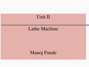
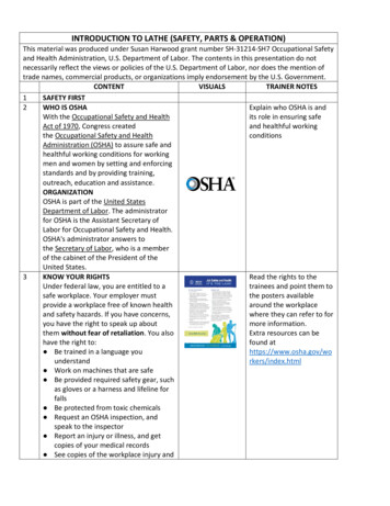
LATHE OPERATIONS - OD1645 - LESSON 1/TASK 1threads. Engine lathes are made in various sizes; the size is determined bythe manufacturer.Generally, the size is determined by the followingmeasurements: either (a) the diameter of the workpiece will swing over thebed, or (b) it will swing over the cross-slide, and (c) the length of thebed, or (d) the maximum distance between centers. For example, using method(a) and (c), a 14 inch x 6-foot lathe has a bed that is 6 feet long and willswing work (over the bed) up to 14 inches in diameter. The maximum distancebetween centers indicates the dimension, in inches, of the longest length ofmaterial that can be placed in the lathe.(2) Bench-Type Engine Lathe.(a) The bench-type engine lathe (figure 1 on the following page), is themost common general purpose screw cutting lathe normally found in a smallshop. It commonly has an 8 to 12 inch swing and a 3 to 5 foot bed length,the size being limited by the practicality of bench mounting.The benchupon which the lathe is mounted may be a standard wood-topped shop bench ora special metal lathe bench with drawers for storing the lathe accessories.(b) The bench-type engine lathe is generally powered by an electricmotor, mounted to the bench behind the lathe headstock, and is driven bymeans of a flat leather belt.Some bench lathes use an underneath motordrive where the drive belt passes through a hole in the bench.Thisarrangement is convenient where space in the shop is limited.The benchtype engine lathe is generally equipped with the necessary tools, chucks,lathe dogs, and centers for normal operation. The lathe may have a quickchange gearbox for rapid change of threading feeds, or gears may have to beinstalled singly or in combination to achieve the proper threading feeds.The bench lathe may or may not have a power-operated crossfeed drive.3
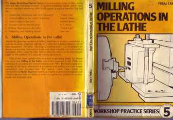
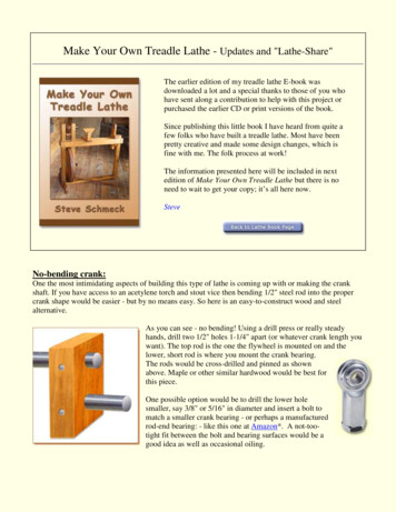
LATHE OPERATIONS - OD1645 - LESSON 1/TASK 1FIGURE 1.BENCH-TYPE ENGINE LATHE.(3) Floor-Mounted Engine Lathe. The floor-mounted engine lathe (figure 2on the following page) or pedestal-type engine lathe, is inherently morerigid than the bench-type lathe and may have a swing as great as 16 or 20inches and a bed length as great as 12 feet, with 105 inches betweencenters.The drive motor is located in the pedestal beneath the latheheadstock.A tension release mechanism for loosening the drive belt isusually provided so that the drive belt may be quickly changed to differentpulley combinations for speed changes. The headstock spindle is back-gearedto provide slow spindle speeds, and a quick-change gearbox for controllingthe lead screw is installed on all currently manufactured floor-mountedlathes.The floor-mounted engine lathe usually has a power-operatedcrossfeed mechanism.(4) Toolroom Lathe.The toolroom lathe is an engine lathe equipped withmore precision accessories and built to greater standards of accuracy thanstandard engine lathes. It may be either floor-mounted or a bench-mounted.The toolroom-type lathe is usually supplied with a very4
LATHE OPERATIONS - OD1645 - LESSON 1/TASK 1precise lead screw for threading operations.It comes equipped withprecision accessories such as a collet, chuck attachment, a taperattachment, and a micrometer stop. Therefore, work of a better class and ofa more complete nature may be accomplished on a toolroom-type engine lathe.FIGURE 2.FLOOR-MOUNTED ENGINE LATHE.(5) Sliding Gap-Type Floor-Mounted Engine Lathe.The sliding gap-typefloor-mounted lathe or extension gap lathe contains two lathe beds, the topbed or sliding bed, and the bottom bed (figure 3 on the following page).The sliding bed mounts the carriage and the tailstock and can be movedoutward, away from the headstock as desired. By extending the sliding bed,material up to 28 inches in diameter may be swung on this lathe.Thesliding bed may also be extended to accept between centers workpieces thatwould not normally fit in a standard lathe of the same size. Except for the5
LATHE OPERATIONS - OD1645 - LESSON 1/TASK 1sliding gap feature, this lathe is similar to the floor-mounted enginelathe.d.Turret Lathes.(1) General. The turret lathe is a lathe used extensively for the highspeed production of duplicate parts. The turret lathe is so named becauseit has a hexagonal turret, or multiple tool holder, in place of thetailstock found on the engine lathe. Most turret lathes are equipped with apump and basin for the automatic application of a coolant or cutting oil tothe workpiece.FIGURE 3.SLIDING GAP-TYPE FLOOR-MOUNTEDENGINE LATHE.(2) Floor-Mounted Horizontal Turret Lathe.The floor-mounted horizontalturret lathe is intended for quick turning of bar stock and chuckedworkpieces with a minimum amount of adjustments between operations.Thelathe uses a collet chuck6
LATHE OPERATIONS - OD1645 - LESSON 1/TASK 1and a hollow headstock spindle for feeding bar stock into the machine, ormay use a universal scroll chuck for swinging the workpiece. The size ofthe horizontal turret lathe is usually given as the diameter of bar stockthat can be fed into the lathe through the headstock spindle. The size canalso be classified by the swing. The turret of the turret lathe is usuallypower operated.It contains an indexing mechanism for bringing the tools(held on its six faces) against the workpiece in a preselected order.Separate feed stops are provided for each face of the turret. A quick handindexing four-sided turret is commonly mounted on the front of the crossslide, and a holder for one or more tools often is mounted on the rear. Thecross-slide may be either hand or power operated.e.Special Purpose Lathes.(1) General.Some lathes have characteristics that enable them to docertain work well.Some of these lathes are of the heavy-production typewhere large numbers of identical parts must be produced to make theoperation more economical. Other special purpose lathes are specialized formachining specific items and cannot be adapted to the common types of latheoperations.(2) Bench-type Jeweler's Lathe.The bench-type jeweler's lathe isactually a miniature engine lathe designed for the precision machining ofsmall parts. The usual jeweler's lathe contains a collet-type chuck, leadscrew, change gears for threading operations, and a precise manualcrossfeed.Controls and feeds are calibrated in smaller increments thanwith the engine lathe and, as a result, workpieces of small dimensions canbe machined to a great degree of accuracy.The jeweler's lathe is beltdriven by an independent motor which can be mounted above or behind thelathe.(3) Other Special Purpose Lathes.Other special purpose lathes includethe production lathe, the automatic lathe, the automatic screw machine, thebrakedrum lathe, the crankshaft lathe, the duplicating lathe, themultispindle lathe, and lathes designed for turning car axles or formingsheet metal.7
LATHE OPERATIONS - OD1645 - LESSON 1/TASK 1f.Essential Features of The Lathe.(1) General.To learn the operation of the lathe, one must first befamiliar with the names and functions of the principal parts. In studyingthe principal parts in detail, remember that all lathes provide the samegeneral function even though the design may differ among manufacturers.Figure 4 on the following page provides a general illustration of the partsnormally found on a lathe. For specific details on a given lathe, refer tothe manufacturer's technical manual for that machine.(2) Bed and Ways. The bed is the base for the working parts of the lathe.The main feature of the bed is the ways which are formed on the bed's uppersurface and which run the full length of the lathe.The tailstock andcarriage slide on the ways in alignment with the headstock. The headstockis normally permanently bolted at one end (at the operator's left).(a) The ways are accurately machined parallel to the axis of the spindleand to each other. The V-ways are guides that allow the carriage and thetailstock to move over them only in their longitudinal direction. The flatway takes most of the downward thrust. The carriage slides on the outboardV-ways which, because they are parallel to the V-ways, keep the carriage inalignment with the headstock and tailstock at all times.This is anabsolute necessity if accurate lathe work is to be done.Some lathe bedshave two V-ways and two flat ways, while others have four V-ways.(b) For satisfactory performance of a lathe, the ways must be kept ingood condition. A common fault of careless machinists is to use the bed asan anvil for driving arbors or as a shelf for hammers, wrenches, and chucks.Never allow anything to strike the ways or damage their finished surfaces inany way. Keep them free of chips. Wipe them off daily with an oiled clothto help preserve their polished surface.(3) Headstock.(a) The headstock carries the head spindle and the mechanism for drivingit.In the belt-driven type headstock, the driving mechanism consistsmerely of a cone pulley that drives the spindle8
LATHE OPERATIONS - OD1645 - LESSON 1/TASK 1FIGURE 4.GEAR-HEAD ENGINE LATHE.directly or through the back gears. When the spindle is driven directly, itrotates the cone pulley. When the spindle is driven through the back gears,it rotates more slowly than the cone pulley, which in this case turns freelyon the9
LATHE OPERATIONS - OD1645 - LESSON 1/TASK 1spindle.Thus two speeds are available with each position of the belt onthe cone; if the cone pulley has four steps, eight spindle speeds areavailable.(b) The geared headstock shown in figure 5 is more complicated but moreconvenient to operate, because the speed is changed by changing or byshifting the gears. This headstock is similar to an automobile transmissionexcept that it has more gear-shift combinations and, therefore, has agreater number of speed changes.A speed index plate, attached to theheadstock, indicates the lever positions for the different spindle speeds.To avoid damage to the gear teeth, the lathe is always stopped before thegears are shifted.FIGURE 5.SLIDING GEAR TYPE HEADSTOCK.(c) Figure 5 shows the interior of a typical geared headstock that has16 different spindle speeds. The driving pulley at the left is driven at aconstant speed by a motor located under the headstock. Various combinationsof gears in the10
LATHE OPERATIONS - OD1645 - LESSON 1/TASK 1headstock transmit power from the drive shaft to the spindle through anintermediate shaft. Use the speed-change levers to shift the sliding gearson the drive shaft and the intermediate shaft to line up the gears indifferent combinations. This produces the gear ratios needed to obtain thevarious spindle speeds. Note that the back gear lever has a high and lowspeed for each combination of the other gears.(d) The headstock casing is filled with oil to lubricate the gears andthe shifting mechanism contained within it. The parts not immersed in theoil are lubricated by either the splash produced by the revolving gears orby an oil pump. Be sure to keep the oil to the full level as indicated onthe oil gage, and drain and replace the oil when it becomes dirty or gummy.(e) The headstock spindle is the main rotating element of the lathe andis directly connected to the workpiece which revolves with it. The spindleis supported in bearings at each end of the headstock through which itprojects.The section of the spindle between the bearings carries thepulleys or gears that turn the spindle. The nose of the spindle holds thedriving plate, the faceplate, or a chuck. The spindle is hollow throughoutits length so that bars or rods can be passed through it from the left andheld in a chuck at the nose.The chuck end of the spindle is bored to aMorse taper to receive the solid center.The hollow spindle also permitsthe use of the draw-in collet chuck (to be discussed later in this lesson).At the other end of the spindle is the gear by which the spindle drives thefeed and the screw-cutting mechanism through a gear train located on theleft end of the lathe.A collar is used to adjust the end play of thespindle.(f) The spindle is subjected to considerable torque because it drivesthe work against the resistance of the cutting tool, as well as driving thecarriage that feeds the tool into the work.Because of the torque andpressure applied to the spindle, adequate lubrication and accuratelyadjusted bearings are absolutely necessary.(4) Tailstock.(a) The primary purpose of the tailstock is to hold the dead center tosupport one end of the work11
LATHE OPERATIONS - OD1645 - LESSON 1/TASK 1being machined between centers. However, it can also be used to hold livecenters, tapered shank drills, reamers, and drill chucks.The tailstockmoves on the ways along the length of the bed to accommodate work of varyinglengths.It can be clamped in the desired position by the tailstockclamping nut.(b) The dead center is held in a tapered hole (bored to a Morse taper)in the tailstock spindle.The spindle is moved back and forth in thetailstock barrel for longitudinal adjustment. The handwheel is turned whichturns the spindle-adjusting screw in a tapped hole in the spindle.Thespindle is kept from revolving by a key that fits a spline, or keyway, cutalong the bottom of the spindle.(c) The tailstock body is made in two parts. The bottom, or base, isfitted to the ways; the top can move laterally on its base.The lateralmovement can be closely adjusted by setscrews. Zero marks inscribed on thebase and top indicate the center position and provide a way to measuresetover for taper turning.(d) Before inserting a dead center, a drill, or a reamer into thespindle, carefully clean the tapered shank and wipe out the tapered hole ofthe spindle. After a drill or reamer is placed into the tapered hole of thespindle, make sure that the tool will not turn or revolve. If the tool isallowed to revolve, it will score the tapered hole and destroy its accuracy.The spindle of the tailstock is engraved with graduations which help indetermining the depth of a cut when a piece is drilled or reamed.(5) Carriage.(a) The carriage carries the crossfeed slide and the compound rest whichin turn carries the cutting tool in the toolpost.The carriage slides onthe ways along the bed (figure 6 on page 14).(b) Figure 6, view B, shows a top view of the carriage. The wings ofthe H-shaped saddle contain the bearing surfaces which are fitted to the Vways of the bed.The cross piece is machined to form a dovetail for thecrossfeed slide. The crossfeed slide is closely fitted to the dovetail andhas a tapered gib which fits between the carriage12
LATHE OPERATIONS - OD1645 - LESSON 1/TASK 1dovetail and the matching dovetail of the crossfeed slide. The gib permitssmall adjustments to remove any looseness between the two parts. The slideis securely bolted to the crossfeed nut which moves back and forth when thecrossfeed screw is turned by the handle.The micrometer dial on thecrossfeed handle is graduated to permit accurate feed.Depending on themanufacturer of the lathe, the dial may be graduated so that each divisionrepresents a 1 to 1 ratio.The compound rest is mounted on top of thecrossfeed slide.(c) The carriage has T-slots or tapped holes for clamping work forboring or milling operations. When the lathe is used in this manner, thecarriage movement feeds the work to the cutting tool which is revolved bythe headstock spindle.(d) The carriage can be locked in any position on the bed by tighteningthe carriage clamp screw.The clamp screw is to be used only when doingwork for which longitudinal feed is not required, such as facing or cuttingoff stock. Normally, the carriage clamp is kept in the released position.The carriage is always moved by hand to make sure that it is free before theautomatic feed is applied.(6) Apron. The apron (figure 2 on page 5) is attached to the front of thecarriage.It contains the mechanism that controls the movement of thecarriage for longitudinal feed and thread cutting. It controls the lateralmovement of the cross-slide.One should thoroughly understand theconstruction and operation of the apron before attempting to operate thelathe. In general, a lathe apron contains the following mechanical parts:(a) A longitudinal feed handwheel for moving the carriage by hand alongthe bed. This handwheel turns a pinion that meshes with a rack gear that issecured to the lathe bed.(b) Gear trains driven by the feed rod.These gear trains transmitpower from the feed rod to move the carriage along the ways and to move thecross-slide across the ways, thus providing powered longitudinal feed andcrossfeed.13
LATHE OPERATIONS - OD1645 - LESSON 1/TASK 1FIGURE 6.CARRIAGE MOUNTED ON THE BED.(c) Friction clutches operated by knobs on the apron are used to engageor disengage the power-feed mechanism. (Some lathes have a separate clutchfor longitudinal feed and crossfeed; others have a single clutch for both.)14
LATHE OPERATIONS - OD1645 - LESSON 1/TASK 1NOTEThe power feeds are usually driven through a frictionclutch to prevent damage to the gears if excessivestrain is put on the feed mechanism. If clutches arenot provided, there is some form of safety device thatoperates to disconnect the feed rod from its drivingmechanism.(d) A selective feed lever or knoblongitudinal feed or crossfeed as desired.isprovidedforengagingthe(e) Half-nuts are used to engage and disengage the lead screw when thelathe is used to cut threads. They are opened or closed by a lever that islocated on the right side of the apron. The half-nuts fit the thread of thelead screw which turns then like a bolt in a nut when they are clamped overit. The carriage is then moved by the thread of the lead screw instead ofby the gears of the apron feed mechanisms. (The half-nuts are engaged onlywhen the lathe is used to cut threads, at which time the feed mechanism mustbe disengaged. An interlocking device, that prevents the half-nuts and thefeed mechanism from engaging at the same time, is usually provided as asafety feature.)(f) The manufacturers of lathe aprons differ somewhat in theirconstruction and in the location of the controlling levers and knobs.However, they are all designed to perform the same function. The principaldifference is in the gear trains for driving the automatic feeds.Forexample, in some aprons there are two separate gear trains with separateoperating levers for longitudinal feed and crossfeed. In others, both feedsare driven from the same driving gear on the feed rod through a commonclutch; they have a selective lever for connecting the drive to either thelongitudinal feed or the crossfeed.(7) Feed Rod.(a) The feed rod transmits power to the apron to drive the longitudinalfeed and crossfeed mechanisms.The feed rod is driven by the spindlethrough a train of gears, and the ratio of its speed to that of the spindlecan be varied by15
LATHE OPERATIONS - OD1645 - LESSON 1/TASK 1changing gears to produce various rates of feed.The rotating feed roddrives the gears in the apron. These gears in turn drive the longitudinalfeed and crossfeed mechanisms through friction clutches, as previouslyexplained in (6)(c) on page 14.(b) Lathes which do not have a separate feed rod have a spline in thelead screw to serve the same purpose. The apron belongs to a lathe of thistype and is driven by the spline in the lead screw. If a separate feed rodwas used, it would drive the feed worm in the same manner.The splinepermits the worm, which is keyed to it, to slide freely along its length toconform with the movement of the carriage apron.(8) Lead Screw.(a) The lead screw is used for thread cutting.Along its length areaccurately cut Acme threads which engage the threads of the half-nuts in theapron when the half-nuts are clamped over it.When the lead screw turnsinside the closed half-nuts, the carriage moves along the ways a distanceequal to the lead of the thread in each revolution of the lead screw. Sincethe lead screw is connected to the spindle through a gear train (to bediscussed in paragraph (9)(a) below), the lead screw rotates with thespindle. Whenever the half-nuts are engaged, the longitudinal movement ofthe carriage is directly controlled by the spindle rotation.The cuttingtool is moved a definite distance along the work for each revolution of thespindle.(b) The ratio of the threads per inch of the thread being cut and thethread of the lead screw is the same as the ratio of the speeds of thespindle and the lead screw. For example: If the lead screw and spindle turnat the same speed, the number of threads per inch being cut is the same asthe number of threads per inch of the lead screw.If the spindle turnstwice as fast as the lead screw, the number of threads being cut is twicethe number of threads per inch of the lead screw.(c) Any number of threads can be cut by merely changing the gears in theconnecting gear train to obtain the desired ratio of the spindle and thelead screw speeds.16
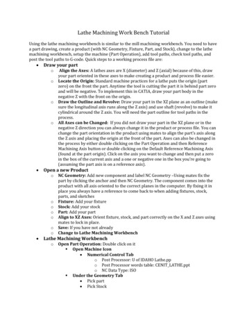
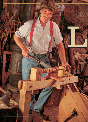
LATHE OPERATIONS - OD1645 - LESSON 1/TASK 1(9) Quick-Change Gear Mechanism.(a) To do away with the inconvenience and loss of time involved inremoving and replacing change gears, most modern lathes have a selfcontained change gear mechanism, commonly called a "quick-change gear box."There are a number of types used on different types of lathes, but they areall similar in principle.(b) The quick-change gear box mechanism consists of a cone-shaped groupof change gears.One can instantly connect any single gear in the geartrain by a sliding tumbler gear controlled by a lever. The cone of gears iskeyed to a shaft which drives the lead screw (or feed rod) directly orthrough an intermediate shaft.Each gear in the cluster has a differentnumber of teeth and hence produces a different ratio when connected in thetrain.Sliding gears also produce other changes in the gear train toincrease the number of different ratios one can get with the cone of changegears.All changes are made by shifting the appropriate levers or knobs.An index plate or chart mounted on the gear box indicates the position inwhich to place the levers to obtain the necessary gear ratio to cut thethreads or produce the feed desired (see figure 7 on the following page).(c) Figure 7 depicts the rear view of one type of gear box. The splinedshaft turns with gear G, which is driven by the spindle through the maingear train mounted on the end of the lathe. Shaft F in turn drives shaft Hthrough the tumbler gear T, which can be engaged with any one of the clusterof eight different size gears on shaft H by means of the lever C. Shaft Hdrives shaft J through a double-clutch gear, which takes the drive throughone of three gears, depending on the position of lever B (right, center orleft). Shaft J drives the lead screw through gear L.(d) Either the lead screw or the feed rod can he connected to the finaldriveshaft of the gear box by engaging the appropriate gears.The lathegear box shown in figure 7 has no feed rod.(e) Twenty-four different gear ratios are provided by the quick-changegear box.The lower lever has eight positions, each of which places adifferent gear in the gear train and hence produces eight different gearratios. The three positions17
LATHE OPERATIONS - OD1645 - LESSON 1/TASK 1FIGURE 7.QUICK-CHANGE GEAR BOX (REAR VIEW).of the upper level produce three different gear ratios for each of the 8changes obtained with the lower lever, thus making 24 combinations in thebox alone.This range can be doubled by using the sliding compound gearwhich provides a high- and low-gear ratio in the main gear train.Thisgives two ratios for every combination obtainable in the box, 48combinations in all.(10) Compound Rest.The compound rest (figure 8 on page 20) provides arigid adjustable mounting for the cutting tool. The compound rest assemblyhas the following principal parts:18
LATHE OPERATIONS - OD1645 - LESSON 1/TASK 1(a) The compound rest swivel (2) can be swung around to any desiredangle and clamped in position. It is graduated over an arc of 900 on eachside of its center position for ease in setting it to the desired angle.This feature is used in machining short, steep tapers such as the angle onbeveled gears, valve disks, and lathe centers.(b) The compound rest top or top slide (3), is mounted on the swivelsection (2) on a dovetailed side.It is moved along the slide by thecompound rest feed screw turning in the nut (4), operated by the handle (5),in a manner similar to the crossfeed described in paragraph (5)(b) beginningon page 12.T
and is the usual lathe found in the machine shop. The engine lathe may be bench or floor mounted; it may be referred to as a toolroom-type lathe, or a sliding-gap or extension-type lathe. The engine lathe consists mainly of a headstock, a tailstock, a carria