Transcription
Unit IILathe MachineManoj Funde
LatheDefinitionLathe is a machine, which removes the metal from a piece of work to the requiredshape and size. Lathe is one of the most important machine tools in the metal working industry. Alathe operates on the principle of a rotating workpiece and a fixed cutting tool. The cutting tool is feed into the workpiece, which rotates about its own axiscausing the workpiece to be formed to the desired shape. Lathe machine is also known as “the mother/father of the entire tool family”.
INVENTOR OF CENTRE LATHE Henry Maudsley was born on an isolated farmnear Gigghleswick in North Yorkshire andeducated at University Collage London. He wasan outstandingly student, collecting ten GoldMedals and graduating with anM.D. degree in 1857.
Function of latheLathe is to remove excess material in the form of chipsby rotating the work piece against a stationary cuttingtool Industrial revolution demanded More production More Precision Changes in Manufacturing process Lead to the Development of High speed Special purpose lathes
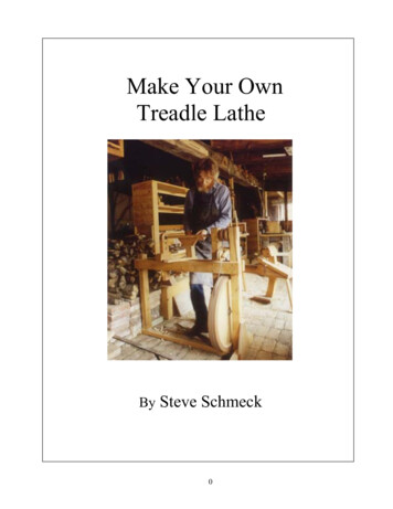
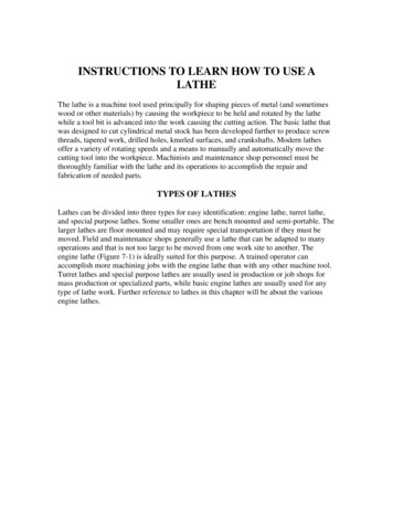
MAIN PARTSLathe Machine is also known as “Centre Lathe”,because it has two centres between which the jobcan be held and rotated.The main parts of centre lathe are: Bed, Head stock, Tail stock, Carriage,etc
Lathe
Lathes Lathes are the oldest machine tools Lathe Components Bed: supports all major components Carriage: slides along the ways and consists of the cross-slide, tool post, apron Headstock – Holds the jaws for the work piece, suppliespower to the jaws and has various drive speeds Tailstock – supports the other end of the workpiece Feed Rod and Lead Screw – Feed rod is powered by a set ofgears from the headstock
Working principle of lathe
Working principle of lathe If the tool moves parallelto work piece cylindricalsurface is formed
Working principle of lathe If the tool movesinclined to the axis itproduces a tapersurface and is calledtaper turning.
Working principle oflathe It holds the work between two supports called centers. Chuck or Face plate is also used for holding the work. Chuck or face plate is mounted on machine spindle Cutting tool is held and supported on a tool post. Movement of the job is rotation about spindle axis Tool is fed against the revolving work Movement of the tool is either parallel to or at any inclination to thework axis
Specifications of Lathe1)a) Height of centersb) type of bed(straight , semi gap, or gap)c) center distance2.a)swing over bedb)swing over cross slidec) swing in gapd) gap in front of face place3.a) spindle speeds rangeb) spindle nosec) spindle bored) taper nose
Specifications of Lathe4)a)Metric thread pichesb)lead screw pitchc)longitudinal feedsd)cross feedsa) cross slide travelb)top slide travelc) tool section6) a)tailstock sleeve travelb)taper in sleeve bore5)7) Motor horsepower and RPM8)shipping dimensions --length*width*height*weight
TYPES OF LATHES Engine Lathe or center lathe It is most common type of lathe and is widely used in workshop. The speed of the spindle can be widely varied as desired which is notpossible in a speed lathe. Bench Lathe Small lathe which can mounted on the work bench It is used to make small precision and light jobs. Speed lathe It is named because of the very high speed of the head stock spindle. Consists head stock, a tail stock and tool post. it has no gear box. Applicable in wood turning, metal spinning and operations.
TYPES OF LATHES Tool room lathe : It is similar to an engine lathe, designed for obtaining accuracy. It is used for manufacturing precision components, dies, tools, jigs etc. and hence it is called as tool room lathe.Special purpose lathes :Gap latheInstrument latheFacing latheFlow turning latheHeavy duty lathe
Automatic Lathe A lathe in which the work piece is automatically fed and removed without use of an operator.It requires very less attention after the setup has been made andthe machine loaded. Turret Lathe Turret lathe is the adaptation of the engine lathe where the tail stockis replaced by a turret slide(cylindrical or hexagonal). Tool post of the engine lathe is replaced by a cross slide which canhold number of tools. Capstan lathe These are similar to turrent lathe with the difference that turret is notfixed but moves on an auxiliary slide. these are used for fastproduction of small parts.
Operating ConditionsCutting speedWorkpieceDepth of cut (d)MachinedsurfaceNChuck Feed (f )ToolChipDepth of cut
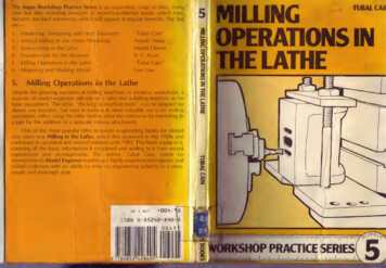
LATHE OPERATIONS Turning: to remove material from the outside diameter of a workpiece toobtain a finished surface. Facing: to produce a flat surface at the end of the workpiece or for makingface grooves. Boring: to enlarge a hole or cylindrical cavity made by a previous processor to produce circular internal grooves. Drilling: to produce a hole on the work piece. Reaming: to finishing the drilled hole. Threading: to produce external or internal threads on the work piece. Knurling: to produce a regularly shaped roughness on the workpiece.
LATHE OPERATIONS
Turning .Cylindrical jobCuttingspeedWorkpieceDepth of cut (d)MachinedsurfaceNChuckFeedToolChipDepth of cut
Turning . Excess Material is removed to reduceDiameter Cutting Tool: Turning Tool Work is held in either chuck or betweencenters. Longitudinal feed is given to the tool either byhand or power.
FacingFlat Surface/Reduce lengthChuckWorkpiecedMachinedFaceCuttingspeedDepth ofcutToolFeed
Facing . machine end of job Flat surface orto Reduce Length ofJob Turning Tool Feed: in direction perpendicular to workpiece axis Length of Tool Travel radius of workpiece Depth of Cut: in direction parallel to workpiece axis
Knurling Produce rough textured surface For Decorative and/or Functional Purpose Knurling Tool A Forming Process MRR 0
KnurlingKnurled surfaceCuttingspeedFeedKnurling toolTool postM ovementfor depth
Grooving Produces a Groove on workpiece Shape of tool shape of groove Carried out using Grooving Tool A form tool Also called Form Turning
Grooving .Shape producedby form toolForm toolFeed ordepth of cutGrooveGroovingtool
Parting Cutting workpiece into Two Similar to grooving Parting Tool Tool rides over – at slow feed Coolant use
Parting .Parting toolFeed
ChamferingChamferFeedChamfering tool
Chamfering Beveling sharp machined edgesSimilar to form turningChamfering tool – 45 ToAvoid Sharp Edges Make Assembly Easier Improve Aesthetics
DrillingDrill – cutting tool – held in TS – feed from TSQuillclampDrillmovingquillTail stockFeedTail stock clamp
Taper TurningD1 D2tan 2L90 D1B AL CD2
Taper Turning.Methods Form ToolSwiveling Compound RestTaper Turning AttachmentSimultaneous Longitudinal andCross Feeds
Taper Turning .by form toolWorkpieceTaperFormStraighttoolcutting edge Directionof feed
Taper Turning ,,by compound restDogMandrel Tail stock quillTail stockFace plateTool post &Tool holderCross slideDirection of feedCompound restSlideCompound rest Hand crank
TAPER TURNINGATTACHMENT
Taper AttachmentI.A bed bracket and keeps the angle plate from moving to the left or the right.II. carriage bracket moves angle plate in a dovetail and keeps the angle plate frommoving in or out on the bed bracket.III. Taper to be cut is set by placing the guide bar, which clamps to the angle plate, at anangle to the ways of the lathe bed.IV. sliding block which rides on a dovetail on the upper surface of theguide bar is secured during the machining operation to the cross slide bar of thecarriage, with the cross feed screw of the carriage being disconnected.V. carriage is traversed during the feeding operation, the cross slide barfollows the guide bar, moving at the predetermined angle from the ways of the bedto cut the taper.VI. It is not necessary to remove the taper attachment when straightturning is desired.
Thread cutting attachment On the lathe internal and external threads are cut eitherwith the help of a thread tool or with the help of tap anddie respectively. Thereshould be a certain relation between jobrevolutions and the revolutions of the lead screw tocontrol linear movement of the tool parallel to the jobwhen the half nut is engaged with the lead screw. The tool should be ground to the proper shape or profileof the thread to be cut. In modern lathes quick change gear box is provided inwhich different ratios of the spindle and lead screw
Lathe Accessories Divided into two categories Work-holding, -supporting, and –driving devices Lathe centers, chucks, faceplates Mandrels, steady and follower rests Lathe dogs, drive plates Cutting-tool-holding devices Straight and offset toolholders Threading toolholders, boring bars Turret-type toolposts
Work holdingDevices Various work holding attachments such as three jaw chucks, collets, and centers can beheld in the spindle. Work is held in the lathe with a number of methods, Between two centres. The work piece is driven by a device called a dog; this method issuitable for parts with high length-to-diameter ratio. A 3 jaw self-centering chuck is used for most operations on cylindrical work-parts. Forparts with high length-to-diameter ratio the part is supported by center on the other end. Collet consists of tubular bushing with longitudinal slits. Collets are used to grasp andhold bar stock. A collet of exact diameter is required to match any bar stockdiameter. A face plate is a device used to grasp parts with irregular shapes.
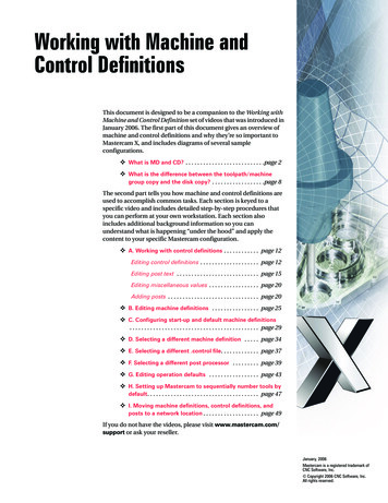
MandrelsFig : Various types of mandrels to hold work pieces for turning. These mandrels areusually mounted between centers on a lathe. Note that in (a) both the cylindricaland the end faces of the workpiece can be machined, whereas in (b) and (c) onlythe cylindrical surfaces can be machined.
Lathe Centers Work to be turned between centers must havecenter hole drilled in each end Provides bearing surface Support during cutting Most common havesolid Morse taper shank60º centers, steel with carbide tips Care to adjust and lubricate occasionally
Chucks Used extensively for holding work for machiningoperations Work large or unusual shape Most commonly used lathe chucks Three-jaw universal Four-jaw independent Collet chuck
Three-jaw Universal Chuck Holds round and hexagonal work Grasps work quickly and accurate within fewthousandths/inch Three jaws move simultaneously when adjusted bychuck wrench Caused by scroll plate into which all three jaws fit Usually has three jaws which move in unison as anadjusting pinion is rotated. The advantage of the universal scroll chuck is its easeof operation in centering work for concentric turning. This chuck is not as accurate as the independent
Four Jaw IndependentChuck Used to hold round, square, hexagonal, andirregularly shaped workpieces Has four jaws Each can be adjusted independently by chuckwrench Jaws can be reversed to hold work by insidediameter
TYPES OF CHUCKThree jawchuck- Forholding cylindricalstock centered.- For facing/centerdrilling,etc.Four-JawChuck- This is independentchuck generally has fourjaws , which are adjustedindividually on thechuckface by means ofadjusting screws
Collet Chuck Thin jobs can be held by means ofmagnetic chucks.Collet chuck isused to hold smallworkpiecesMagnetic ChuckThin jobs can beheld by means ofmagnetic chucks.
Work holding DevicesChucksusually equipped with3 or 4 jaws3 jaw chucks generallyare self centering.Used for roundwork pieces.Can be centered within.025mmindependently.4 jaw chucks are forsquare, rectangular,or odd-shaped workpieces Can bepoweractuated(a) and (b) Schematic illustrations of a draw-in-type collets. The workpiece isplaced in the collet hole, and the conical surfaces of the collet are forced inward bypulling it with a draw bar into the sleeve. (c) A push-out type collet. (d)Workholding of a part on a face plate.
Headstock SpindlesUniversal and independent chuck fitted to threetypes of headstock spindles1. Threaded spindle nose Screws on in aclockwise directionTapered spindle nose2. Held by lock nutthat tightens on chuck46-50
Headstock SpindlesCam-lock spindle nose3. Held by tightening cam-locks using T-wrenchChuck aligned by taperon spindle noseRegistration lines on spindle noseRegistration lines on cam-lockCam-locksCam-lock mating stud onchuck or faceplate46-51
Collet Chuck Most accurate chuck Used for high-precision work Spring collets available to hold round, square, orhexagon-shaped work pieces Each collet has range of only few thousandths ofan inch over or under size stamped on collet
Collet Chuck Special adapter fitted into taper of headstock spindle, and hollow draw barhaving internal thread inserted in opposite end of headstock spindle. It drawscollet into tapered adapter causing collet to tighten on workpiece.
Types of LatheDogs Standard bent-tail lathe dog Most commonly used for roundworkpieces Available with square-head setscrewsof headless setscrews Straight-tail lathe dog– Driven by stud in drive plate– Used in precision turning46-54
Types of LatheDogs Safety clamp lathe dog Used to hold variety of work Wide range of adjustment Clamp lathe dog– Wider rangethan others– Used on allshapes
Left-Hand Offset Toolholder Offset to the right Designed for machining work close to chuck orfaceplate and cutting right to left Designated by letter L
Right-Hand Offset Toolholder Offset to the left Designed for machining work close to the tailstockand cutting left to right Also for facing operations Designated by letter R
Straight Toolholder General-purpose type Used for taking cuts in either direction and forgeneral machining operations Designated by letter S
Straight Tool holder General-purpose type Used for taking cuts in either direction and forgeneral machining operations Designated by letter S
Semi automatic lathes Semi automatic lathes are production lathes with human involvement forcertain operations Semi automatic lathes are production lathes with human involvement forcertain operations Capstan and turret lathes with additional attachments become semiautomatic lathes Also called retrofitting Vide range of jobs can be accommodated Higher production rates
Semi AutomaticLathes Designed for short continuous runs Turret or ram in place of tailstock Indexable square tool post on cross slide Suitable for Drilling, countersinking, reaming, tapping like operations Turret and Capstan lathes are examples In Turret lathe Turret moves along with saddle In Capstan lathe turret slides over the ram
Turret LatheCapable of performing multiplecutting operations on the sameworkpiece Turning Boring Drilling Thread cutting FacingTurret lathes are very versatileTypes of turret lathes Ram-type: ram slides in aseparate base on the saddle Saddle type: more heavilyconstructed Used to machine largeworkpeiceces
Turret lathe
Capston Lathe
Turret Lathe These machines are capable ofcarrying out multiple cuttingoperations on the sameworkpiece. Several cutting tools aremounted on a tetra, penta, orhexagonal turret, whichreplaces the tailstock. These tools can be rapidlybrought into actionagainst the workpiece one byone by indexing the turret.
Comparision of turret & engine latheTurret lathe Turret lathes are relatively morerobust and heavy duty machines.work on chucking type jobs held inthe quick acting chucksThe heavy turret being mounted onthe saddle which directly slides withlarger stroke length on the mainbedOne additional guide rod or pilot baris provided on the headstock of theturret lathes to ensure rigid axialtravel of the turret headwhereas in turret lathes externalthreads are generally cut, ifrequired, by a single point ormultipoint chasing tool beingmounted on the front slide andmoved by a short leadscrew and aCapstan lathe Capstan lathes generally dealwith short or long rod type blanksheld in collet, In capstan lathe, the turret travelswith limited stroke length within asaddle type guide block, calledauxiliary bed, which is clampedon the main bed External screw threads are cut incapstan lathe, if required, using aself opening die being mounted inone face of the turret,
AUTOMATIC LATHES
AUTOMATIC LATHES Machine tools in which components are machined automatically. The working cycle is fully automatic that is repeated to produce duplicate parts without participation of operator. All movements of cutting tools, their sequence of operations, applications, feeding ofraw material, parting off, un loading of finished parts all are done on machine. All working & idle operations are performed in definite sequence by control systemadopted in automatic which is set up to suit a given work. Only operation reqd to be performed manually is loading of bar stock/ individualcasting/ forged blanks. These machines are used when production requirements are too high for turret lathesto produce economically.
Automatic Lathes Manual machine controls replaced by various mechanisms Parts are fed and removed automatically May have single or multiple spindles Automatic lathes uses servo motor Automatic lathes Limited ranges of variety and sizes
Automatic Lathe Features Minimum man power utilized Meant for mass production Manual machine controls replaced by various mechanisms To eliminate the amount of skilled labour. Mechanisms enable to follow certain prescribed frequency Parts are fed and removed automatically Minimizing the loading and unloading time May have single or multiple spindles Tool set up may be permanent May have horizontal or vertical spindles More accuracy can be obtained
Advantages Greater production over a given period. More economy in floor space. Improvement in accuracy. Floor space maintenance and inventory requirements are reduced. More consistently accurate work than turrets. More constant flow of production. Scrap loss is reduced by reducing operator error. During machine operation operator is free to operate another machine/ caninspect completed parts.
CLASSIFICATION OF AUTOMATICLATHES Depending up on type of work machined these machines are classified as:1.Magazine loaded Automatics: Machines used for producing components from separate blanks. Also called as automatic checking machines.2.Automatic Bar Machines: designed for machining components from bar/ pipe stock.M/c’s are used for manufacture of high quality fasteners (screws, nuts),bushings, shafts, rings, rollers, handles which are usually made of bar / pipestock.
Depending upon number of work spindles, automatic lathes are classified as:1.Single SpindleAutomatics.2.Multi SpindleAutomatics. Depending upon purpose & arrangement of spindle also automatics areclassified as:1.Purpose General & single purpose m/c.2.Arrangement of spindle Horizontal & vertical
I)Type of Single SpindleAutomatics:a) Automatic Cutting Off Machine:
These machines produce short w/p’s of simple form by means of cross slidingtools. Machines are simple in design. Head stock with spindle is mounted on bed. 2 cross slides are located on bed at front end of spindle. CAMS on cam shaft actuate movements of cross slide through system of levers.Operation: The reqd length of work(stock) is fed out with a cam mechanism, up to stockstop which is automatically advanced in line with spindle axis at each end ofcycle. Stock is held in collet chuck of rotating spindle. Machining is done by tolls that are held in slides operating only in cross wisedirection. Typical simple parts (3 to 20 mm dia) machined on such a machine is shown infig.
b) Single spindle Automatic Screwm/c:
Used for producing small screws(12.7 to 60 mm dia) generally, but also inproduction of all sorts of small turned parts. These are completely automatic bar type turret lathes, designed for machiningcomplex internal & external surfaces on parts made of bar stock/separate blanks. Up to 10 different cutting tools can be employed at one time in tooling of this kindof screw machine. 2 cross slides(front & rear) are employed for cross feeding tools. Vertical tool slides for parting off operation may also be provided . Head stock is stationary & houses the spindle. Bar stock is held in collet chuck & advanced after each piece is finished & cut off. All movements of machine units are actuated by cams mounted on cam shaft.
Bar stock is pushed through stock tube in a bracket & its leading end isclamped in rotating spindle by means of collet chuck. By stock feeding mechanism bar is fed out for next part. Machining of central hole is done by tools that are mounted on turret slide. Parting off/ Cutting off, form tools are mounted on cross slide. At end of each cut turret slide is with drawn automatically & indexed tobring next tool to position.
c) Swiss type automatic screw/Sliding headscrew:
As name implies in this m/c head stock is movable & tools are fixed. These machines are used for machining long accurate parts of small diameter.(2 to25mm). Bar stock is held in rotating collet in head stock & all longitudinal feeds areobtained by cam which moves entire head stock as unit. Rotating bar stock is fed through hard bushing in centre of tool head. Tool head consists of 5 single point tools is placed radially around bushing. Mostly diameter turning is done by 2 horizontal slides, other 3 slides used foroperations such as knurling, chamfering, cutoff. Tools are controlled & positioned by cams that bring tool in as needed to turn,face, form, cutoff w/p from bar as it emerges from bushing. Close tolerances0.005 to 0.00125 mm are obtained.
II) Multi SpindleAutomatics: These are fastest type of production machines and are made in a variety ofmodels with 2,4,5,6,8 spindles. In contrast with single spindle m/c where one turret face at a time isworking on one spindle, in multi spindle m/c all turret faces works on allspindles at same time. Production capacity is higher, machining accuracy is lower compared tosingle spindle. Because of longer set up time, increased tooling cost this machines areless economical than other on short runs, more economical for longerruns.
a) Parallel Action Automatics/ Multiple Flow m/c:
In this type of machine same operation is performed on each spindle, w/p isfinished in each spindle in one working cycle. It means that No. of components being machined No. of spindles in machine. Rate of production is high & machine can be used to machine simple parts onlysince all the machining processes are done at one position. These machines are usually automatic cutting off bar type machines, used toperform same work as single spindle automatic cut off machines. Machine consists of frame with head stock at right end. Horizontal work spindles that are arranged one above the another are housedinthis head stock. Cross slides are located at right & left hand sides of spindles & carry crossfeeding tools. All working & auxiliary motions of machine unit are obtainedfromCAM mounted on cam shaft.
b) Six Spindle Progressive Action MultiSpindle:
In this design of machine, the w/p is machined in states & progressively in stationafter station. Head stock is mounted on left end of base of machine. It carries spindle carrier which rotates about a horizontal axis through centreofmachine. Working spindles are mounted on this spindle carriers. Spindles carry collets & bars from which w/p’s are machined. Bar stock is fed through each spindle from rear side. On face of spindle carrier support are mounted cross slides which carry tools foroperations such as cutoff, turning, facing, forming, chamfering.
No. of slides No. of spindles. Main tool slide (end tool slide) extends from middle of this support. Fed of each tool, both cross slide & end tool slides is controlled by its ownindividual cams. In this diagram spindle carrier indexes on its own axis by 60 at each cuttingtoolretraction. As spindle carrier indexes, it carries work from one station to another stationwhere different tolls operate on work. Stock moves round the circle in counter clock wise direction & returns to stationno. 6 for cutting off.
Tool layout
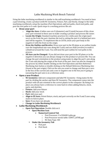
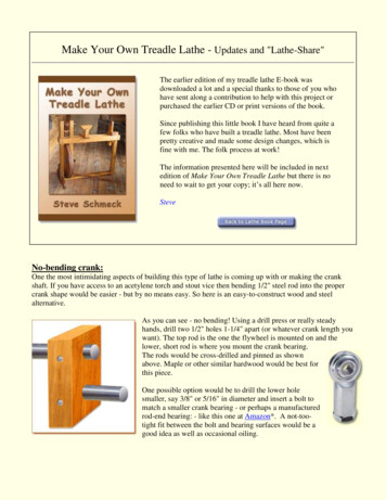
Tool layoutschematically showing the type and configuration of Atypical tool layout for a particular job being machined in asingle spindle automatic lathe is schematically shown in Fig.
Tool layout and camdesign Pre determined plan for order and method off machiningoperations necessary to produce it . Following steps arerecommended for lay out for an automatic lathe.
Machining Calculations:Turning Spindle Speed - N v cutting speed Do outer diameter Feed Rate - frin/min)(rpm)vN π Dofr N(mm/min -or-f f feed per rev Depth of Cut - dd in/rev) Do outer diameterTm Df final diameter Machining Time - Tm L length of cutDo D f2LfrMRR v f Mat’l Removal Rate - MRR(mm/rev -or-(min)d(mm3/min -or- in3/min)
Thank You !!!
Lathe Definition Lathe is a machine, which removes the metal from a piece of work to the required shape and size. Lathe is one of the most important machine tools in themetal working industry.A lathe operates on the pr