Transcription
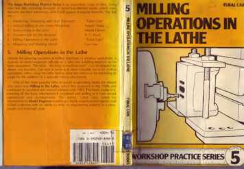
The Argus Workshop Practice Serjes is an expanding range-of titles, mannew but also including revisions of recently-published books which havebecome standard references, which! will appear at regular intervals. The firstare:1.Hardening, Tempering and Heat\ Treatment"Tubal Cain"2. ' Vertical Milling in the Home Wo'kshopArnold Throp3.Screwcutting in the LatheMartin Cleeve4.Foundrvwork for the AmateurB. T. Aspin5.Milling Operations in the Lathe"Tubal Cain"6.Measuring and Marking MetalsIvan Law5,Milling Operations in the LatheDespite the growing numbers of milling machines in amateur workshops, amajority of model engineers still rely on a lathe and a drilling machine as thebasic equipment. The lathe, "the king of/machine tools", can be adapted foralmost any function, but next to turning its most valuable use is for millingoperations, either using the lathe itself tc drive the cutters or by extending itsscope by the addition of a separate mi ing attachment.One of the most popular titles in nodel engineering books for almostsixty years was Milling in the Lathe, w lich first appeared in the 1920s andcontinued in up-dated and revised editions until 1983. This book replaces it,covering all the basic information it contained and adding to it from recentexperiences and developments. The author, Tubal Cain, needs nointroduction to Model Engineer readers is a highly experienced engineer andskilled craftsman with an ability to write1 on engineering subjects in a clear,simple and thorough style.GB net D0M .ISBN Q-flSEME-flTUBAL CAIIMILLINGOPERATIONS IN-tun ATUC
MILLINGOPERATIONSIN THE LATHEbyTubal CainARGUS BOOKS LIMITED
Argus Books LimitedWolsey House,Wolsey Road,Hemel Hempstead,Hertfordshire, HP2 4SSEnglandKINGSTONLIBRARIESW375.SEc Argus Books Ltd 1 984ALLcCAT,'?1CLASSrjJ l9 IREFSO'BNDlidAll rights reserved. No part of this publication may bereproduced in any form, by print, photography, microfilmor any other means without written permission from thepublisher.ISBN 0 85242 840 5Phototypesetting by Performance Typesetting, Milton KeynesPrinted and bound by A. Wheaton & Co. Ltd., ExeterCONTENTSChapter 1Introduction —the Lathe as a Milling MachineChapter 2Milling Cutters612Chapter 3Tooth Geometry, Speeds and Feeds and Cutter Holding23Chapter 4Workholding33Chapter 5Milling Attachments42Chapter 6Indexing and Dividing52Chapter 7Procedures and Case Studies70Chapter 8Combined Operations and Complex MillingChapter 9Care of cutters88111Appendices1 17Index123
CHAPTER 1Fig. 2. Ornamentaldrills, as used in Fig. 1.Introduction — the Latheas a Milling MachineThe lathe is by far the most versatile of allmachine tools. Though developed as aproducer of "solids of revolution", workingbetween centres, the introduction of theheadstock - a very long time ago rendered the production of flat surfacespossible and "surfacing” techniques arementioned in almost every written recordof the lathe. When turning became aleisure occupation - about 400 years agoso far as we know - the wish to applydecoration to plain turned work resulted inthe development of a number of auxiliarydevices. Some, like the "Rose Engine",were effectively a different machine, andneed not concern us. But one device,introduced very early, is what was knownas the "drilling instrument".Fig. 1 shows that fitted to a lathe madeby Holtzapffel in 1 805. The toolholder isremoved and the spindle set in its place.Driven by an "overhead” gear from thetreadle and used in conjunction with thedividing circles on the mandrel pulley(this, too, being a very early device)patterns of holes could be produced bothFig. 1. Drilling spindleof a lathe made in1805, fluting with aform-drill.6on the surface and on the cylinder. Thedrills could be plain or profiled (some areshown in Fig. 2) and quite elaboratepatterns could be produced. The "instru ment" could also be used to produceflutes, of plain or complex profile, bytraversing the spindle using the feedscrewof the sliderest. In conjunction with theOrnamental Chucks, already highlydeveloped even at that time, quite remark able work could be done.Whilst the origin of the Drilling Instru ment is unknown, the introduction of whatmight be termed "revolving tool cutters"is certainly due to Holtzapffel. No doubthe was influenced by the "Wheel CuttingHg 3. The "Verticalcutting frame.7
Fig. 4."Horizontal"cutting frame.Engines" (which were not lathes) of theclock-maker. The first two to be applied tothe lathe were the "Vertical " and the"Horizontal" cutting frames, the adjectivein each case referring to the plane ofrevolution of the cutter. Figs 3 & 4. Again, nthe cutter itself could be plain or profiled.We need not concern ourselves with theuses for which they were devised, but it isclear that normal slotting and groovingcould be done and that the vertical framecould be and was used as a gear-cutter.These two were followed very quickly bythe "Universal" cutting frame, of whichFig. 5 is a relatively modern example(Birch, c.1912). This accepts the sametype of tool, but the plane of revolutioncan be set at any angle, with obviousadvantages. (This example is geared, butmost were direct driven).The next development (possibly about1825?) was perhaps the most ingeniousand certainly the most valuable to theornamental turner, and has its lessons forthe model engineer as well. This was the"Eccentric" cutting frame, Fig. 6. It is, ineffect, a micrometer adjustable flycutter,and it speaks much for the work ofCharles Holtzapffel that it was calibratedon the index to 0.005 inch. Using cuttersidentical to those for the other cuttingFig. 5. A geared "Universal" cutting frame, byBirch-8Fig. 6. The "Eccentric"cutting frame.frames (Holtzapffel was a pioneer of suchstandardisation) its powers were verygreat indeed. Again, we need not be con cerned with "Ornamental " work, butsuffice it to say that used in conjunctionwith the mandrel dividing index it cangenerate accurate polyhedral solids, andeven a perfect hemisphere.It is interesting to observe that the useof such cutting frames was confinedentirely (so far as we can tell) to theamateur ornamental turner. No doubt theneeds of the engineering industry of theday were such that there was no call forsuch devices. However, it is interesting tofind that the first application of a rotarytool seems to have been devised for themaking of special hexagon nuts — for amodel! Fig. 7 shows the arrangementdevised in 1829 by James Nasmyth whenworkingwithMaudslayon themanufacture of special collar-nuts. Thesewere needed for a model of one of Maudslay’s large marine engines. The cutter isdescribed as a "circular file” and wascarried in the lathe mandrel, while thecircular indexing device was mounted onFig. 7. A collar-nut milling machine devised byJames Nasmyth, c 1829. The forerunner of themilling machine.the slide rest. This was so successful thata larger machine was purpose-made forthe works, for use on nuts for the full-sizeengines. Perhaps not'the first (and cer tainly not the last) occasion where the"model engineer" has led the way!The amateur ornamental turner, andthe model engineer if he had such a lathe,now had facilities for producing flatsurfaces, cutting slots, gear forming and"1 I.AU-NIT I TTINi. M vrUINK.9
similar, for fluting, and for the generationof accurate prismatic solid shapes.Naturally the ornamental turner was mostconcerned with "decoration" but as thepractice of making engineering models"for fun" developed more and more usewas made of these facilities, but adaptedto the small engineer's lathe. The cuttingframes were made more robust (Fig. 8 is adevice by Britannia of 1880) and the"turner" became accustomed to usingmilling cutters on his lathe. The dividingcircles on the headstock pulley were lesselaborate but the associated index wasmade strong enough to meet the higherforces involved in cutting metal. But largeflat areas were produced by filing, on handplaning or shaping machines, or on thelathe faceplate. The majority of the millingwork done on the lathe used relativelysmall cutters. In Volume 1 of ModelEngineer, October 1898, a prize of 2 wasawarded to a Mr. R.B.Matthews for anarticle "The Lathe as a Milling Machine".His devices included the drilling spindle, arobust eccentric cutting frame, a verticalcutting frame, an arbor for carrying cutterson the lathe mandrel, and an indexingworkholder.10LIMITATIONS OF THE MACHINEWriters often refer to the "disadvantages"of the lathe when used as a miller, buttrue disadvantages are few. The chief isthe fact that the lathe lacks one of theessential movements. Work can be traver sed across the axis of the mandrel andalong it, but not in the vertical plane. Thismeans that an extra vertical slide must beadded if full use is to be made of millingprocesses. The second disadvantage isthat except when carrying cutters on anarbor between centres (a relatively rareoperation) all work has to be attached to avertical surface, which makes fordifficulties in setting. On the other hand,most modern lathes do possess onefeature found on few small millers — aconsiderable speed range. Many modelengineers' lathes can be operated atspeeds between 25 and 2000 rpm, andalmost all can be run at 40 or 50 rpm.This, as we shall see later, is a very impor tant attribute.The machine has, however.considerableLIMITATIONS. The first and most seriousis lack of RIGIDITY. All milling involves acontinuous sequence of shock loads, andthe lathe is not designed to withstandthese. Even a small milling machine willhave some 20 to 25 sq. ins. of slidewaybearing surface, whereas it is a good 3Inch lathe which provides 10 sq.ins. onthe saddle, with less on the cross-slide.(And even less still on any vertical slide).The mandrel housing of a miller is veryrobust compared with that available in alathe headstock, and there is no com parison between the rigidity of the bed ofa lathe compared with a miller of compar able price.The power available at the lathemandrel is small; it is true that millingmachines designed largely for amateuruse may have about the same power butthis is probably due to "the market"having become accustomed to that limit.But it does mean that many commercialcutters will be far too large for use on thelathe.The third limitation is the "daylight"available. Using the word "tall" to indicatelength along the axis of cutter rotation, thefact that a lathe can accept perhaps 12Inches between work and cutter face isirrelevant; the overhang is too great,whereas with light cuts the sameworkpiece could comfortably be carriedon the horizontal table of a miller. Again,there is but limited space between the topof the cross-slide and the lathe axis perhaps a couple of inches. A comparablemilling machine would accept 6 inches.This situation does limit the work whichcan be done, especially in facing largecastings.These latter circumstances are,perhaps, not "serious", for much modelengineering work will fall within the limitof dimension so imposed. But the limit ofpower and rigidity does mean that even ahalf-inch end-mill cannot be used at itsfull capacity on mild steel or cast iron. Thecrux of the matter is, then, that rate ofmetal removal must be adjusted to suitthe machine. Provided this is alwaysborne in mind (and assuming that thework can be accommodated in the space)there is little that can be done on a propermilling machine that cannot be done on alathe; it will just take a little more time,that is all.
CHAPTER 2Fig.10.Showingthevariation in chipthickness whenprofiling.Milling CuttersThe action of the tooth of a milling cutteris quite different from that of a lathe tool.Fig. 9 shows that, with the normalrotation relative to the feed, the effectivedepth of cut is small at the first engage ment of the tooth, rising to a maximum atthe edge of the workpiece. There will be asudden release of energy as the chipleaves the parent metal and even ifanother tooth has started to cut furtherround the cutter (as it should, if goodpractice is being followed) there will be amarked "spring back” both of the cutteron its arbor and of the work support. If therotation is in the opposite direction theshock comes at engagement, but thisstyle of cutting ("down-cut milling")should never be used on a lathe, as in theabsence of backlash eliminators in thefeed-nuts the feed is uncontrollable. In Fig.10 I show the case of the cutter which hastooth engagement over almost the wholediameter, as might be used in light facingwork. Here the depth of cut first increasesand then diminishes. There will be muchless shock loading, but there is still con siderable fluctuation of force liable tocause vibration.Early types of cutters were designedwith a large number of teeth - some evenlike rotary files - in the hope that thiswould lessen the problem. In this theywere effective, but only at the expense ofsurface finish and accuracy. Finishsuffered because there was not enoughspace between the teeth to accommodatethe chips formed during the tooth travel.Accuracy was poor because it was(especially in the early days) difficult togrind every tooth to the same radius ofaction. Modern cutters have fewer teeth(Fig. 11) and when used properly thetooth spacing will be arranged such thatone tooth starts to cut before the previousone has finished. This action is helped byarranging the teeth as a helix. Fine pitchcutters may be necessary, however,especially when cutting thin material ortaking fine cuts.TYPES OF CUTTER TOOTHTeeth may be of two forms. Fluted Teeth,Fig. 12, are designed to be sharpened onthe top land. The means that the diameterof the cutter is reduced each time it issharpened. This does not matter on thoseused for facing, but must be rememberedif it is used for cutting a slot, or if dimen sional work is being done using feedscrewindexes and allowing for the size of cutter.The clearance angle of the tooth is main tained by setting over the grinding wheel.Relieved Teeth, Fig. 13, are used whenthe profile of the cut must be maintained,as on a gear-cutter or form tool. In thiscase the tooth is sharpened by grindingthe flat front face ONLY, the tooth profilehaving been maintained all the way downthe "relief". These cutters are ratherexpensive, as a special form relievingmachine is needed for their manufacture.The "angle of relief" provides a constantFig. 9. Chipformationwhen milling.FEED.12At itsthickest partthe chip willbe about0.003 inchthick.Hg.11. Fine andcoarse pitch toothcutters.13
Fig. 12. "Fluted-or "Gashed" tooth cutter.clearance angle throughout.It should be noted that many flutedtooth cutters are used for accurate dimen sional profiling - the slot drill is a case inpoint. Fortunately the model engineerdoes not subject his cutters to the amountof wear found in industry and it will oftensuffice simply to grind the end face of thecutter, as it is the sharp corner whichsuffers most. However, when such cuttersare used it is only prudent to rememberthe sharpening problem, and to set upcutting conditions which will minimisewear. In which connection it should benoted that this does NOT mean reducingthe cut to a "shave"; this will be dealt withlater, but it can be said now that millingcutters must CUT, and cuts of "the oddthou" are just those most likely to take theedge off.Left, Fig. 15.Side &Face Cutter.Below,Fig.14.F'9- 13. "Form Relieved" teeth, which have thesame profile throughout.TYPES OF CUTTER1. The Slabbing Cutter. Fig. 14. This isillustrated for completeness, as no lathelikely to be used by a model engineer willhave sufficient power available to drive it,nor be rigid enough to carry it. As its nameimplies, it is used to face slabs or largesurfaces. It is often misnamed as a "RollerMill" - quite a different tool, used forreducing billets to bars in a steelworks byrolling I2. The Side-and-Face Cutter. Fig. 15. Thishas teeth on the sides or faces as well ason the cylinder, and when used on anarbor between centres can machine thevertical surface of the work. It can be usedfor cutting slots but, of course, once theface teeth had been ground would not bedimensionally accurate as to width. Avariant is the Slotting Cutter, Fig. 16. Thishas teeth on the circumference only - it isreally a narrow slabbing cutter.Resharpening does not reduce the width.but on the other hand, with thick work thepitch must be large enough to provideadequate chip clearance. If necessary thework may have to disposed with thecutter almost tangentially (Fig. 18) toensure adequate tooth contact.4. Angle-cutters, Fig. 19. These, as theirname implies, are cutters for forming veegrooves or bevels. They may be single ordouble angle, and in the latter case thetwo angles can be different if need be.Special cutters of this type can be had forfluting the teeth of home-made millingcutters and, with a radius at the point, forfluting taps and reamers.5. Formcutters. Fig. 20. As alreadyoxplained, these must always be of theTop left, Fig. 16. Slotting Cutter, with no teethon the sides. Top, Fig. 17, Slitting Saw. Above,Fig. IB. How more teeth can be brought intocontact when using a coarse-pitch saw.Bottom left, Fig. 19. Angle Cutter. Below, Fig.20. Form relieved gear cutter.3. Slitting Saw. Fig. 17. These arerelatively thin variants of Fig. 15 and 16;some have teeth on the sides, some not,but the term "saw" is usually applied onlyto those without. Primarily intended ascutting-off tools they can be used to formnarrow slots. Thicknesses vary from aslow as 0.004 inch up to 1/4 inch, but it isdoubtful whether a 3 inch lathe couldcope with much above 1/8 inch. Selectionof tooth pitch is important; there shouldnever be less than three teeth in contact.1514
Fig. 21. Endmill (Photo Clarkson International)form-relieved type. That shown is a gearcutter, but the profile can be of anyreasonable shape. Accurate setting-up ofboth work and cutter is important as evenslight deviations can distort the shape(Though at times advantage may be takenof this fact, to produce a non-standardform. A semi-circular form cutter could,for example, be offset to cut the gulletshape of a cutter tooth).6. The End-mill. All the cutters so farmentioned are designed to be mounted onan arbor - either between centres or heldin a chuck. The end-mill. Fig. 21, is alwaysheld in a chuck. That shown has ascrewed shank for use in a special colletchuck (by far the most accurate and safestFig. 22. Design(maximum)cutting condi tionsforanendmill.way) but they can be had with plainshanks. They have teeth on the cylinderand on the end, the former usually (andpreferably) helical in form. Though oftenused as facing cutters their prime functionis profiling, the design cutting conditionbeing shown in Fig. 22, with themaximum depth of cut equal to the cutterdiameter and maximum width one quarterof the diameter. They are somewhatunhappy cutting a width more than halfLeft, Fig. 23. Shell Endmill (Photo ClarksonInternational)Below. Fig. 24. It is helpful to bevel the teethof cutters used purely for facing.16the diameter even if the depth is reducedaccordingly. Note that if the machine isIncapable of accepting the full cut shownIn Fig. 22 the axial depth of cut should bereduced, not the width, for it is importantthat at least two teeth should be engaged.THEY ARE NOT INTENDED FORCUTTING SLOTS and will not cut todimension if so used. If a slot MUST becut with an end-mill then it should be of adiameter less than the width of the slotond a cut taken down each side separately- with the work-traverse opposing therotation of the teeth, of course.7. Shell End-mills. Fig. 23. Large(relatively) diameter end-mills on a solid hank would be expensive, and the shellend-mill is an alternative. It is normallyheld on a short arbor, and retained with anullen screw and thick washer. The drive isnormally taken through a cross-keyongaging in a slot in the back face, but formodel engineers' work the friction drive isoften sufficient. If need be a small peg canbe fitted on the collar of the arbor to takethe drive. Some may be threaded for useon a screwed holder. Though they are,precisely, end-mills and intended for use In Fig. 22, their larger diameter makesthorn very handy for facing work.However, if they (or, indeed, any end-mill)aro to be used exclusively for facing it isworth while to chamfer the tooth cornershown in Fig. 24. This corner suffersrapid wear and spoils the cutting action, specially on light finishing cuts, and achamfer will make a considerableImprovement. However, it is fairly impor tant to ensure that each tooth is equal,and If a cutter-grinder is not available it isbast merely to stone a very small bevel on ach tooth. A suitable arbor for suchOuttors is shown on page 30.(. The "Rippa" cutter. Fig. 25. This is, inaffect, an end-mill with chip-breakers onIho teeth. The ordinary cutter produces aFig. 25. The Clarkson "RIPPA" type endmill(Photo Clarkson International).chip which is long in relation to itsthickness, and this can lead to difficulties- and also limits the depth of cut. The"Rippa" is formed to make a series ofoverlapping grooves, each having adiscrete chip. The rate of metal removalcan be much greater - in sizes belowabout 1 inch diameter the total area of cutcan be as much as four times that of astandard end-mill, though the feed-ratemust be reduced somewhat. Provided suf ficient power is available at the mandrelthe cutter can shift metal at about twicethe rate. The finish is surprisingly good onthe vertical surface as the multiple "teeth"are arranged in a helix, and is equal to thatof an end-mill on the face.End-mills, shell and solid, and Rippacutters can be used as small slabbingcutters, but care must be taken, first not tooverload them and second, not to reducethe load by reducing the depth of cut.0.003 to 0.005 inch should be theminimum. Judgement must be used; thecutter is projecting as a cantilever and theFig. 26. Comparison between "Standard" and"Long" endmills.17
Fig. 27. The Slot Drill; note the unequal lengthof face teeth. (Photo Clarkson International)Fig. 28. Left to Right: Corner-rounding,Dovetail, and Woodruffe keyway cutters.cutting forces can be high - very high ifthe cutter is not really sharp. "LongSeries" cutters (Fig. 26) are available, butthese are not really intended for use aswide slabbing cutters but rather to reachdown below the top of a tall workpiece.9. The Slot-drill. Though having theappearance of an end-mill this cutter isquite different. First it has two (sometimesthree) teeth (Fig. 27) instead of the usualFig. 31. Holderfor FC3 cuttersmade from aJacobs Chuckarbor.four or more. Second, on the end face onetooth extends across the centreline. Thismeans that the cutter can be plungeddown straight into a face, which cannot bedone with an end-mill. If the cutter issharpened only on this end face it will cuttrue to dimension, provided the chuckholding it runs true. The finish on the sidesof the slot is far better than can be hadfrom a multi-tooth end-mill. They can beused for facing, but not for profiling. Thecorrect (maximum) cut is of a depth equalto half the cutter diameter though thismust, of course, be reduced to suit thepower available and the rigidity of bothcutter — and work-holder.10. Tee-slot and Dovetail Cutters. Fig. 28.These serve the purposes which theirnames imply. In both cases it is necessaryto rough out a plain slot first. In the caseof the tee-slot cutter the "size" is some times quoted as the size of the bolt forwhich the slot is needed. One side of theslot is cut at once - they are not slot-drills.The cutters have many applications andinverted dovetail, or "bevelling" cuttersare available. Fig. 28 also shows a CornerRounding cutter.11. Woodruffe Keyway Cutter. Fig. 28.This is similar in shape to the tee-slotcutter. Its diameter and width correspondsto the British Standard or MetricWoodruffe key. It has teeth on theIFig. 29. A set ofClarksonFC3'Throwaway" cutters;also available with ballends. (Photo ClarksonInternational)18circumference only. Model engineersseldom need this type of key, but thecutter can be used for slotting connectingrods and for ordinary keyways. The neck isconveniently reduced in diameter adjacentto the head, to clear the shaft being cut.12. Ball-ended slot drills. These havetwo teeth as a rule, the end beingground to a radius equal to half the cutterdiameter. Their main application is thecutting of grooves and flutes, thoughwhen set at an angle to the radius of thework they can be used for gulleting. Beingslot drills they can be used in a plungingcut to form the seat for a ball-joint. Caremust be taken in regrinding, as otherwisethe true spherical form will be lost.13. 'Throwaway"cutters. Fig. 29. This is afairly recent introduction, being so cheap(relatively) that in industry they are notworth the time needed to sharpen them.They are three-fluted slot drills which can,within the limitation of length, be used asond-mills. The cutters are surface treatedafter hardening and cut remarkably freely.The maximum diameter available is 0.250Inch and sizes down to 1/16 inch dia canbo had on y-inch shank. Standard and' long series" (Fig. 30) are available, as areHg.30."Long"typeClarkson International).rFC3cutter(Photoball ended cutters. All have the samediameter of shank and they are usuallyheld in a Morse taper adaptor, as seen inFig. 31. This type of cutter is ideal for suchwork as port-milling and the like.SINGLE POINT CUTTERS. The cutters sofar illustrated are commercial types(though they can be home-made in somecases) and are more or less costly. Thesingle-point milling cutter, often called aFLY-CUTTER, is, for many jobs, anadequate substitute provided its limita tions are realised, and can very quickly bemade in the workshop. That shown in Fig.32, for example, is no more than a pieceof --inch diameter silver steel bent toshape and hardened at the tip. They areparticularly applicable to facing work inbrass and light alloy, where the cuttingspeed can be high enough to avoid theneed for a low feed-rate.This is the first limitation. Suppose wehave a fly-cutter to- sweep 2 inchdiameter. For carbon steel on cast iron asafe cutting speed is about 25ft/min. Themandrel speed will then be about 48 rpm.Even at a feed rate of 0.010 in/rev —which would leave a tolerable, but not agood, finish - the feed-rate can be nomore than about.-j-inch/minute which withthe normal cross-slide feedscrew, meansa "handle rate” o*f 5 rpm; not too easy tokeep steady. We shall have more to sayabout the relative merits of fly-cutters andfacing cutters or end-mills for facing largeareas later.19
Fig. 32. Facing a gunmeral cylinder with asimple but effective flycutter.The second difficulty arises from thedesign of the lathe itself. All lathes are (orshould be) designed to machine aworkpiece very slightly concave whencarried on the faceplate. This means thatthe cross-slide is not EXACTLY at rightangles to the mandrel axis. This is veryslight - perhaps 0.002 to 0.003 in./footwhen the tolerance on headstock align ment is allowed for. But it does mean thatthe tool point will cut on the upwardsreturn stroke at the back of the workpiece.This will not matter if the travel of thecross-slide is sufficient to permit the workto run right past the sweep of the cutter,but as fly-cutting is usually resorted toFig. 33. A boring head used as a flycutter. Notethe white-painted backpiate behind.20when the work is too large in area topermit this there will be a discontinuity ofcut part way across the surface. Thedifficulty can at first sight be overcome byreversing the normal traverse direction —i.e. bringing the cross-slide forward sothat the tool cuts on the backstroke. Thisis well enough for light work, but thegolden rule when milling should be toensure that cutting forces are downwardsonto the flat shears of the bed. In anycase, if the work is too long to clear thecutter completely this will not serve.The first difficulty can be mitigated byusing high-speed steel (or even carbide)but this cannot be manipulated in theform shown in Fig. 32. However, Fig. 33shows an ordinary BORING HEAD (thephoto shows the "A.B.C.") set up as afacing cutter. The tool is a 3/8 dia HSStool-bit and the radius can be adjustedboth by setting over the tool at an angleand by using the micrometer setting slide.This arrangement can be used for"milling" large diameter circular facings,by adjusting the micrometer after each 2or 3 revolutions; tedious, perhaps, buteffective.Fig. 34 shows another alternative. Herea normal (though rather large section!)boring bar is held in the 4-jaw chuck toprovide a flycutter of very large sweep. Itmight be thought that the ordinary "bent"boring tool could be used, but unfor tunately the cutting edge faces the wrongway. It is NOT advisable to reverse therotation of the lathe to meet this, as theinterrupted cut could cause the chuck tounscrew from the mandrel nose. Frankly, Ihesitated before using a fly-cutter of suchlarge sweep, but on one occasion when Ineeded one I applied the device similar tothat shown in Fig. 35. Here a bolt hasbeen drilled to accept a 3/1 6 inch dia HSStoolbit and this can be secured at anydesired radius on the lathe faceplate.a low figure, as much to achieve a goodfinish as to avoid wear.ODD CUTTERS. All model engineers haveexperienced the situation where the oddjob arises and there is no alternative but tomake a special tool. Fig. 37 is a small veecutter made to cut the vee grooves in abrass slide for an old piece of machinery.The cone was first turned, the materialbeing silver steel, and then three flutesmilled out with a slot-drill fed endways.Fig. 34. A large radiusflycutter. based on/aheavy boring bar.'Fig. 35. (right! Flycuttermounted on faceplate.(Photo Derek Beck)Fig. 36. Form-fly cutter.'FORM FLYCUTTING. Shaped flycuttersare, of course, in common use as gearcutters for small pitch clock gears, but thisis not the only application. Fig. 36 showsthe profile of a flat cutter made todecorate the entablature of a model beamengine. It is carried in a cutting framesho
5, Milling Operations in the Lathe . Despite the growing numbers of milling machines in amateur workshops, a majority of model engineers still rely on a lathe and a drilling machine as the basic equipment. The lathe, "the king of/machine tools", can be adapted for almost any function,