Transcription
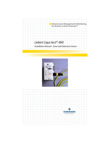
Infrastructure Management & MonitoringFor Business-Critical Continuity Liebert Liqui-tect 460Installation Manual - Zone Leak Detection Sensor
TABLE OF CONTENTSINTRODUCTION . . . . . . . . . . . . . . . . . . . . . . . . . . . . . . . . . . . . 1EXTERIOR DIMENSIONS AND MOUNTING DETAILS. . . . . . . . . . . 1PLACEMENT ON SUBFLOOR UNDER COOLING SUPPORTEQUIPMENT . . . . . . . . . . . . . . . . . . . . . . . . . . . . . . . . . . . . . . 2POWER WIRING . . . . . . . . . . . . . . . . . . . . . . . . . . . . . . . . . . . 3WIRING TO AUXILIARY ALARM PANELS . . . . . . . . . . . . . . . . . . 4CONFIGURATION SWITCH SETTINGS . . . . . . . . . . . . . . . . . . . . 5Leak Detect Filter Delay(SS1) . . . . . . . . . . . . . . . . . . . . . . . . . . 5Latching or Non-Latching Alarms (SS2) . . . . . . . . . . . . . . . . . . 5Alarm Retest Delay (SS3) . . . . . . . . . . . . . . . . . . . . . . . . . . . . . . 6LED OPERATION . . . . . . . . . . . . . . . . . . . . . . . . . . . . . . . . . . 7NOTES . . . . . . . . . . . . . . . . . . . . . . . . . . . . . . . . . . . . . . . . . . 7INSTALLATION OF LEAK DETECTION SYSTEM CABLE . . . . . . . . 8LEAK DETECTION KIT INSTALLATION SCENARIOS . . . . . . . . . 10i
ii
IntroductionLiebert Liqui-tect Leak Detection Sensors install quickly and worksimply for reliable detection of conductive aqueous fluid leaks.The Liqui-tect 460 Sensor provides zone protection using the easy-toinstall and quick-drying Liebert leak detection cable. LEDs located onthe top cover of the module provide visual indication. A reset buttonprovides optional manual acknowledgement of alarms.The top cover is hinged, allowing easy access to the electronics housedinside the steel enclosure. Terminal blocks allow easy interconnectionof power and alarm outputs.Dual Form-C relay outputs can simultaneously signal the local alarmpanel and remote monitoring system. The Liqui-tect 460 Sensor features supervised operation through alarms for cable faults, circuit failure or loss of power, ensuring a completely self-monitored leakdetection system.The LT460 is conveniently available in packaged kits with 20, 25, 30,35 or 45 feet of leak detection cable and hold-down clips. Note thatadditional cable cannot be added to packaged kits.The LT460 sensor can also be purchased independently. The sensorcan accommodate up to 100 feet of leak detection cable if the sensorand leak detection cables are purchased as independent components.Exterior Dimensions and Mounting DetailsTOP VIEW4.75"(120.65mm)FRONT VIEW4.25"(108mm)LeakdetectioncableconnectorForm-C relayoutputs &power wiringconnection3.25"(83mm)4.75"(121mm)Shipping weight: 2 Ibs (0.9 kg)Mounting holes: #8 screws12"(51mm)
Placement on Subfloor Under Cooling SupportEquipment(Other applications such as long perimeter walls can be monitored)To a Liebertenvironmentalunit andan optional*monitoringpanelTo externalpowersupply ordirectlyfromunit(seePower Wiringon page 3)LeakdetectioncableLeak detectionzone (directlybeneath unit)LT460* Output connections to external alarm monitoring panelssuch as the Liebert contact closure alarm panelsAs shown above, the Liqui-tect 460 (LT460) may be placed on a subfloor, where it is connected to the leak detection cable that surroundsthe leak detection zone—the area directly beneath the unit beingprotected or other areas such as the perimeter of a room.Note: For a downflow unit, the leak detection cable must belocated six feet in front of the unit.The LT460 requires a 24 VAC power supply either from the environmental unit or an external source. There are two sets of Form-C drycontacts for connection to a Liebert environmental unit and an external monitoring panel.For more information: See Installation of Leak Detection System Cable on page 8 forinstructions on installing the cable and proper placement of thehold-down clips. See Leak Detection Kit Installation Scenarios on page 10 forcable placement, distance from the unit, and part numbers.2
Power WiringThe LT460 is rated for 24 VAC, 50/60 Hz and 0.12 amp.Figure 124V from Liebert environmental units to LT460Challenger, Himod orLiebertDeluxe System/3,MM2DS,(8 Ton)LT460Challenger, Himod or Mini-Mate2 (8 ton)LT460TB1TB1TB1TB1T5 (24V)T5 (24V)TB1-1TB1-1G5 (Ground)(Ground)G5TB1-2TB1-2Liebert MM2 (1 to 5 Ton)LT460TB1Power Wiring4V transformer of(24V)here are noated terminal24V(Ground)from Lieberttions)TB1-1Environmental Unit to LT460Liebert Deluxe Sys/3,24V fromHimodTransformerChallenger,orMM2 (8 Ton)T5 (24V)connectionon Liebert unitto LT460LT460LT460TransformerTB1TB1TB1T5 (24V)G5TB1-2Location ofFrom 24Vtransformer(Ground)MM2 (1 to(15 toTon)LiebertLiebertMini-Mate25 ton)TB1-1TB1-1TB1-2TB1-2LT460LT460TB1TB14V transformer of(24V)here are noFrom24Vated B1-2* Requires a 24V external transformer (there areno designated terminal connections on the unit)Figure 224V from Transformer to LT46024V from transformer to 1-1From24V24VFromtransformertransformerTB1-2TB1-23
Wiring to Auxiliary Alarm PanelsThe LT460 has two Form-C dry contact alarm output contacts (TB2 &TB3). Each contact is rated for 24 VAC at 3 amp.Figure 3LT460 to Liebert environmental unitsLiebert Deluxe Sys/3,Challenger, Himod orMM2Liebert(8 Ton) DSLT460LT460TB2EnvironmentalEnv.unitUnitTB2-3 (N.C.)(N.C.)TB2-3TB2-2 (C)(C)TB2-2(24V)24 (24V)TB2-1 (N.O.)(N.O.)TB2-150, 51, 55 or 5651LT460Liebert Deluxe System/3,Liebert MM2 (1to 5 Ton)orChallenger,HimodMini-Mate2 (8 ton)LT460TB2EnvironmentalEnv.unitUnitTB2-3 (N.C.)(N.C.)TB2-3TB2-2 (C)(C)TB2-224 (24V)TB1-1(24V)TB2-1TB2-1 (N.O.)(N.O.)TB1-251, 55 or 56LT460LT460TB2TB2ORLiebert MM2(1 to 5 Ton)LiebertMini-Mate2(1 to 5 ton)EnvironmentalEnv.unitUnitTB2-3 (N.C.)(N.C.)TB2-3TB2-2 (C)(C)TB2-2TB1-1 (24V)(24V)TB2-1 (N.O.)(N.O.)TB2-1TB1-2 or TB1-3TB1-3Figure 4LT460 to Liebert contact monitor panelLT460LT460Liebert ContactLiebertcontactMonitor PanelmonitorpanelTB2TB2-3(N.C.)(N.C.)TB2-3Alarm C)TB2-2TB2-1(N.O.)(N.O.)TB2-14
Configuration Switch SettingsA four-position DIP switch is used toselect two alarm (filter) delays andthree mutually exclusive alarmmodes. The switches are locatednext to the wiring terminationblocks.1.2.3.4.Leak Detect Filter Delay(SS1)ContactsRating:Switch SettingsLeak Detect FilterAlarm LatchAlarm Retest DelayNot UsedS1OFF ON10sec 2minNoYesNo1hr——ALL CIRCUITS: CLASS 2Contacts shown in POWERED, NON-ALARM state24V,3ATB3-3TB3-2TB3-1N.C.C2N.O.SS1 selects the leak detect filterN.C.TB2-3delay, the interval for which a leakContactsCRating:TB2-2condition must be continuously124V,3ATB2-1N.O.detected before an alarm is24Vtriggered:TB1-250/60HzTB1-1OFF 10 seconds (default)0.12AON 2 minutesCONNECT ENCLOSURE TO EARTH GROUNDThis feature is useful for eliminating nuisance alarms. SS1 worksindependently of the settings of SS2and SS3. While the alarm delay is selectable (factory default isOFF 10 seconds), the cable fault delay is preset at approximately2 seconds.Latching or Non-Latching Alarms (SS2)SS2 selects latching or non-latching alarms, the setting in which analarm will latch ON until manually reset:OFF Non-latching (default)ON LatchingThe factory default is OFF Non-latching. If the sensor is in latchingmode (ON Latching) and the leak condition clears itself in theinterim, a manual reset is required. While the alarm is latched, thesensor goes into a “sleep” mode and power to the leak detection cableis discontinued. De-powering the cable prevents damage to the cableshould it be in contact with the conductive liquid for an extendedduration. After a manual reset, the sensor resumes its normal operation, continuously checking for leaks. If the leak condition has not yetcleared but the sensor is manually reset, the sensor will re-alarm afterthe appropriate leak detect filter delay. SS2 in the ON position willdisable the operation of SS3.5
Alarm Retest Delay (SS3)SS3 selects the alarm retest delay, the setting in which an alarm islatched and retested every hour.OFF Non-latching (default)ON Latching-retest each hourThe factory default is OFF Non-latching. If SS3 ON and a leak isdetected, the alarm condition is latched, the sensor goes into a “sleep”mode and power to the leak detection cable is discontinued. After onehour, the sensor will automatically retest if the leak is still present. Ifthe leak has cleared itself, the sensor deactivates the alarm, resetsitself and resumes normal operation; if the leak is still present, thealarm condition remains activated and the sensor goes to “sleep” andretests in another hour. This procedure will repeat indefinitely untilthe leak is cleared or until the alarm is manually reset.A manual reset can be initiated at any time. If the leak condition hasnot yet cleared, the sensor re-alarms after the selected leak detect filter delay; if the leak has cleared, the sensor deactivates the alarm andresets itself. SS3 is disabled if SS2 ON.The factory default settings of SS2 OFF and SS3 OFF place thesensor in a non-latching, continuous retest mode. The sensor does notgo to “sleep” after detecting a leak—instead, it continually checks todetermine whether the leak condition has cleared itself. Alarms automatically reset when the leak condition clears. Initiating a manualreset will cause the sensor to trigger the alarm again after the selectedleak detect filter delay. The leak detect cable remains powered at alltimes.SS4 is not g, 10-second filter delay(factory default)ONOFFOFF(notused)Non-latching, 2-minute filter delayOFFON—(notused)Latching, 10-second filter delayONON—(notused)Latching, 2-minute filter delayOFFOFFON(notused)1-hour latch/retest, 10-second filter delayONOFFON(notused)1-hour latch/retest, 2-minute filter delay6
LED OperationLiqui-tect etCableFaultSystem Normal (Green): ON continuously when power is appliedto sensor.Alarm Pending (Yellow): ON continuously during leak detect filterdelay and cable fault delay. FLASHING (with Leak Detected LED) toindicate cable fault condition.Leak Detected (Red): FLASHING to indicate leak detectedalarm. FLASHING (with Alarm Pending LED)to indicate cable fault condition.NotesThis equipment has been tested and found to comply with the limitsfor a Class A digital device, pursuant to part 15 of FCC rules. Theselimits are designed to provide reasonable protection against harmfulinterference when the equipment is operated in a commercial environment. This equipment generates, uses, and can radiate radio frequency energy and, if not installed and used in accordance with theinstruction manual, may cause harmful interference to radio communications. Operation of this equipment in a residential area is likely tocause harmful interference in which case the user will be required tocorrect the interference at his own expense.In the event of a severe leak causing submersion or partial-submersion of the enclosure and/or the electronic circuitry inside the enclosure, the entire module should be returned to the factory forinspection.7
Installation of Leak Detection System Cable1. Attach the leak detection cable to the LT460 module.2. Activate module and test detection cable. (Touch detection cablewith a clean moist cloth or paper towel.) Dry detection cable toremove the alarm condition. (A hair dryer can be used to speed upthe drying.)Note: Do not try to saturate the detection cable for testing! It onlyrequires a small amount of water to alarm. The detection cable willhave to dry for the alarm condition to clear.DETECTION CABLE PLACEMENT PRECAUTIONS Do not use detection cable that is damaged or dirty—forexample, from plaster, spackle or construction debris. Detection cable should not be dragged through contaminants(dirty or greasy areas). Floor must be clean for the detectioncable to function properly and for the hold-down clips toadhere to the floor surface. Careful consideration should be taken to place detection cableout of the direct discharge airflow path of environmentalequipment. This type of equipment can discharge moistureinto the airflow. Place cable six feet from discharge to avoidnuisance alarms during humidification. Tools or heavy objects can do permanent damage whendropped, rolled, or set on the detection cable. Avoid foot trafficon the detection cable as well. Do not use any type of adhesive tapes to secure the detectioncable. Do not allow soldering or welding near the detection cablewithout providing protection from heat or contaminants. (Alsoavoid installing the detection cable in or near these type ofareas.) Mild dishwashing liquid can be used to clean the detectioncable of many contaminants.3. Once the cable passes the test, lay it in the pattern desired.8
4. The installation of the hold-down clips should be in pairs accordingto Figure 5 with the following considerations:Figure 5Installation of hold-down clips in pairsa. One pair every 6 to 8 feet in straight patterns (see Figure 6).b. One pair every 3 to 4 feet in circular patterns (see Figure 7).c. One pair at the beginning and end of the arc when turning90 degrees (see Figure 8).d. One pair as needed to maintain consistent uniform contactbetween the floor and detection cable.Figure 6Cable laid instraight patternsFigure 7Cable laid incircular patternsHold-downclips every3-4 ft.Hold-downclips every6-8 ft.Figure 890 turn in cableHold-downclips atbeginning &end of arc5. Be certain the detection cable is protected from the adhesive installation for the hold-down clips. No adhesive should come in contactwith the detection cable.6. Once adhesive is completely dry, snap the cable into each hold-downclip.7. Check that there are no gaps between the floor and detection cable.(Add clips as required.)8. Be certain there are no alarms present on the module.9. Do final testing as per instruction in Step 2.9
Leak Detection Kit Installation undentire unitDetectionon sides andin front of unit2-ft clearancein front2-ft clearancein frontDownflowUnitDownflowUnitDetectionaroundentire unitDetectionon sides andin front of unit6-ft clearancein front6-ft clearancein frontDistance from unitDistance:In backOn sidesIn front2 ft2 ft2 ftNo cable behind2 ft2 ftUnit1 ft1 ft6 ftNo cable behind1 ft6 ftPart number(footprint-in.)Challenger(32.5 x LT460-Z20LT460-Z35LT460-Z25(50 x 35)LT460-Z30LT460-Z20LT460-Z35LT460-Z25(74 x 35)LT460-Z35LT460-Z20LT460-Z35LT460-Z25Himod(69 x 35)Deluxe System/3(99 x 35)LT460-Z45LT460-Z25LT460-Z45LT460-Z30(122 x 35)LT460-Z45LT460-Z25LT460-Z45LT460-Z30(73 x 35)LT460-Z35LT460-Z20LT460-Z45LT460-Z30(86 x 35)LT460-Z35LT460-Z20LT460-Z45LT460-Z30DS(98 x 35)LT460-Z45LT460-Z25LT460-Z45LT460-Z30(109 x 35)LT460-Z45LT460-Z25LT460-Z45LT460-Z30(132 x 35)LT460-Z45LT460-Z25LT460-Z45LT460-Z3010
Ensuring The High AvailabilityOf Mission-Critical Data And Applications.Technical Support / ServiceWeb erson.com800-222-5877Outside North America: 00800 1155 4499Single-Phase UPS & Server side North America: 00800 1155 4499Three-Phase UPS & Power Systems800-543-2378Outside North America: 614-841-6598Environmental Systems800-543-2778Outside the United States: 614-888-0246LocationsUnited States1050 Dearborn DriveP.O. Box 29186Columbus, OH 43229EuropeVia Leonardo Da Vinci 8Zona Industriale Tognana35028 Piove Di Sacco (PD) Italy 39 049 9719 111Fax: 39 049 5841 257Asia29/F, The Orient Square BuildingF. Ortigas Jr. Road, Ortigas CenterPasig City 1605Philippines 63 2 687 6615Fax: 63 2 730 9572While every precaution has been taken to ensure the accuracy and completeness of this literature, Liebert Corporation assumesno responsibility and disclaims all liability for damages resulting from use of this information or for any errors or omissions. 2010 Liebert CorporationAll rights reserved throughout the world. Specifications subject to change without notice. Liebert is the registered trademark of Liebert Corporation.All names referred to are trademarks or registered trademarks of their respective owners.SL-31045 REV5 12-11Emerson Network Power.The global leader in enabling Business-Critical Continuity EmersonNetworkPower.comAC PowerOutside PlantConnectivityPower Switching & ControlsDC PowerPrecision CoolingEmbedded ComputingRacks & Integrated CabinetsEmbedded PowerServicesInfrastructure Management & MonitoringSurge ProtectionEmerson, Business-Critical Continuity, Emerson Network Power and the Emerson Network Power logo aretrademarks and service marks of Emerson Electric Co. or one of its affiliated companies. 2010 Emerson Electric Co.
Liebert Mini-Mate2 (1 to 5 ton) LT460 * Requires a 24V external transformer (there are no designated terminal connections on the unit) Challenger, Himod or MM2 (8 Ton) TB1 T5 (24V) G5 (Ground) LT460 TB1 TB1-1 TB1-2 Transformer LT460 TB1 TB1-1 TB1-2 From 24V transformer 24V from Transformer to LT460 Liebert MM2 (1 to 5 Ton) LT460 TB1