Transcription
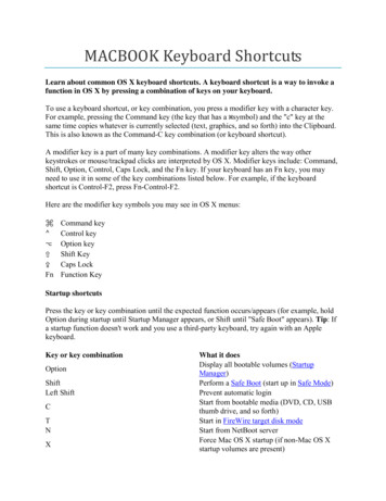
GV-KeyboardInstruction Manual2005/03Before attempting to connect or operate this product,please read these instructions carefully and save this manual for future use.
GV-KeyboardGV-KeyboardTable of ContentsRXIntroduction1Packing List1System RequirementsP1F1F2TXP2P3F4F31P5F5RECREC STOP1System ConnectionsP4ALLSCHSCH STOP2Speed Rear Panel Overview2Connecting GV-Keyboard to One GV-System3Connecting GV-Keyboard to Multiple IntroductionUSB Driver5The GV-Keyboard is used to program and operate GV-Systems. ThroughGV-Keyboard Application7InstallationRS-485 configuration, it can control up to 16 additional GV-Systems.Defining Eight Function Keys8Printing Function Key Labels9Packing ListID & Password Settings in DVRs10GV-Keyboard x 1Keyboard Overview11USB Cable (300 cm) x 1Programming and Operation14On-Screen Display Menu15AC Adapter (Input 100-240 V) x 1The OSD in Main System16Wall Terminal Block x 1The OSD in ViewLog17Shortcut key Conflict Test18Troubleshooting19Specifications20RS-232 Cable (300 cm) x1RJ-11 (RS-485) Cable (100 cm) x 1System RequirementsWindows 2000 or XPGV-System V7.0 or above1
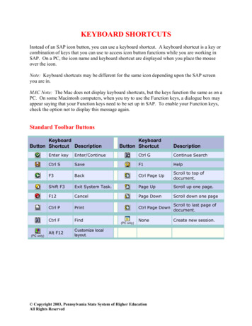
GV-KeyboardGV-KeyboardSystem ConnectionsConnecting GV-Keyboard to One GV-SystemRear Panel OverviewThere are four ways to connect the keyboard and one GV-System, using:12V - GRESETDC 12V12TERMUSBRS232RS485RS485OFF NO345671 ResetResets the keyboard when it does not respond to commands.2 DC IN 12V PowerConnects to the AC adaptor's DC output plug.3 USB PortConnects to GV-System.4 RS-232 PortConnects to GV-System.5 Terminal BlockThe terminal block carries RS-485 signals.1USB Port,2RS-232 Port (DC power required),3Terminal Block (DC power required), or4RJ-11 Port (DC power required)GV-SystemIt can connect up to 16 additional GV-Systems.6 RJ-11 Port1234The RJ-11 port carries RS-485 signals.Through the wall terminal block, it can connect up to12V - G16 additional GV-Systems.RESETDC 12V7 Terminal Resistance Used in the last daisy-chained GV-System.USBRS232RS485TERMRS485OFF NOGV-Keyboard*1 USB cable, 2 RS-232 cable, and 4 RJ-11(RS-485) cable are supplied withthe GV-Keyboard.23
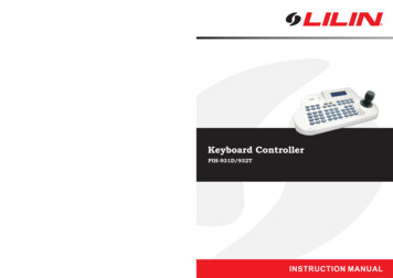
GV-KeyboardGV-KeyboardConnecting GV-Keyboard to Multiple GV-SystemsThere are two ways to connect the keyboard and up to 16 additionalWall Terminal BlockGV-Systems within 600 meters, using:1Terminal Block, or2RJ-11 PortRS-232 (COM port)GV-System 1Wall TerminalBlock *Connects to PC'sPower SupplyWhiteRJ-11 Cable6Function1GND212V3DATA-4DATA 512V6GND1. When you are using the wall terminal block for connection, the RS-485 and RS485 - cables should be attached to the appropriate terminal screws.2. It's not necessary to use extra power for RS-485 connection if the keyboardadaptor is connected.USB DriverIf you are using the USB port to connect the keyboard and GV-System, it'sRS-485-necessary to install the USB driver. These instructions are for Windows XP.Installation under Windows 2000 is similar, but not necessarily identical.GV-NET Card **RS-232 (COM port)GV-System 16USBBluePinInstallationRS-485 DC 12VBlackNote:GV-NET Card **RESETYellow* RJ-11 Cable1RS-485-RS-485 Cableto RJ-11 Port *RedConnects to PC'sPower SupplyRS-485 orGreenRS23212V - GTERMRS485OFF NORS4851. Use the USB cable to attach the keyboard to GV-System.2. The Found New Hardware Wizard detects the keyboard and pops up.2 RJ-111 Terminal Block***4The RJ-11(RS-485) cable and Wall Terminal Block are supplied with the GV-Keyboard.The GV-Net card can be replaced with other GV products, such as GV-Net,GV-Net I/O card, and GV-Hub.5
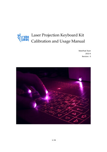
GV-Keyboard3. Select Install from a list of specific location (Advanced), and then click Next.4. Check Include this location in the search, and then click the Browse button tolocate the folder that contains the driver. The driver is located at the installationGV-Keyboard6. To verify that the driver is installed correctly, go to Windows Device Manager. Inthe Ports (COM & LPT) field, you should see the entry for Prolific USB-to-SerialBridge.CD:\GV7.0\Driver\GV Keyboard and Hub.Note: Remember the COM port showing in the Prolific USB-to Serial Bridge entry.It indicates the port number that the keyboard is using.GV-Keyboard ApplicationTo run the GV-Keyboard application, follow these steps:1. Execute mcamctrl.exe from the GV-System folder.5. Click Next to display this warning window, and then click Continue Anyway.2. The Mulitcam Controller window should display.67
GV-KeyboardGV-KeyboardThe controls in the Multicam Controller window:NameDescriptionDVR IDSelects the desired DVR ID for connection.DVR NameGives the login DVR a descriptive name.PortSelects the port connecting to the keyboard.Startup typeSelects Manual or Automatic to run Mulitcam Controller at nextstartup.Starts the service.Stops the service.F1 - F8Print IconDefines eight function keys on the keyboard to control outputPrinting Function Key Labelsmodules, display layout, PTZs, and cameras.The Print Memo allows you to print out the label for the eight functionPrints out a label for the eight function keys.keys (F1 - F8) so that you can attach it on the keyboard for instantreference.Defining Eight Function KeysF1 - F8 options allow you to assign these features to the eight functionkeys on the keyboard:Output Control1. Click the Printer icon. This displays the Printer Memo window.2. Under every field from F1 to F8, type the information that you want to printon the label. The words you type will also appear on Preview fields forprint preview.3. Click Print.Display LayoutPTZ Preset GoPTZ AutoCamera SelectStart/Stop Camera ScanNote: For the PTZ Preset Go and PTZ Auto functions, you must map the PTZcamera first in Main System.89
GV-KeyboardID & Password Settings in DVRsGV-KeyboardKeyboard OverviewSection AFor the keyboard operation, you must export IDs and Passwords fromLCD displayGV-Systems first. And these settings are restricted for digits.RXTX1. Click the Configure button, and select Password Setup. This displays theP1Password Setup dialog box.F1P2F2P3P4F4F3F5RECREC STOP1ALLP5SCHSCH STOPSpeed cusOutAutoPresetOKMenuCancelA-BSpeed-0Section BSection CSection AYellow POWER LEDRed RX LED (Receive)Green TX LED (Transmit)2. Select a user from the user list, and then check Export this ID for IR RemoteControl (GV-Keyboard). This allows the export of its ID and Password.When logging in the GV-System, you will see the exported ID in the ID drop-down listof the Login dialog box.10P1Changes DVR IDP2Configures the keyboard parameters, including password,key beep and auto-lock periodP3Displays the firmwave versionP4-5Reserved for future featuresLocks the keyboard11
GV-KeyboardGV-KeyboardF1-F8Moves one frame forwardFunction keysStops a video eventSection BLaunches Multicam Surveillance System (Main System)Sets the starting and ending frames for auto playingLaunches ViewLogSpeed Turns full screen view on/offSpeed-Increases playback speedDecreases playback speedSwitches the screen divisionsSwitches to previous screenTurns the sound on/offSwitches to next screenPlays next events automaticallyNumeric buttonsRECREC STOPStarts/Stops recordingSection CSCHSCH STOPStarts/Stops the scheduled recordingZoomInZooms in the display image of PTZ camera in MainSystem; Zooms in the display image in ViewLogGoes to previous eventZoomOutZooms out the display image of PTZ camera in MainSystem; Zooms out the display image in ViewLogGoes to next eventFocusInIncreases the focus of PTZ camera in Main SystemPlays/Pauses a video eventFocusOutDecreases the focus of PTZ camera in Main SystemRewinds/Pauses a video eventAutoFocusAuto FocusMoves one frame backAutoSets the PTZ camera for auto mode112A-BALLEnters the login password; Selects a specific camera;Changes the Time Setting in ViewLog13
GV-KeyboardGV-KeyboardHomeMoves the PTZ camera to the default positionPresetMoves the PTZ camera to a preset locationChanging DVR IDPress P1, and enter a two-digit DVR ID.Changing password 1. Press P2, enter a password, and pressto browseLCD displays.2. When "Password Change" appears, pressOKMenuCancelCalls up the Login dialog box; Enters the settings; Opensthe OSD menuCloses the OSD menu; Returns to the previous menu;Calls up the menu to exit Main System or ViewLogOKMenuand entera four-digit password.Disabling/Enablingkey beep1. Press P2, enter a password, and pressto browseLCD displays.2. When "Audio Setting" appears, pressOKMenuand pressto enable/disable the key beep.Setting auto-lockPTZ control; Navigates the display image in ViewLog;Navigates the OSD menu; Changes the Time Setting inViewLogperiod1. Press P2, enter a password, and pressto browseLCD displays.2. When "Auto Time Lock" appears, pressOKMenuand enter anidle period after which the keyboard is automatically locked.* The keyboard can be used only if the correct passwordis entered.Setting A to B frame 1. Pressfor auto-playing. The message "A To B Mode (Set A)" appearson the screen.2. PressProgramming and OperationA- BA- Bagain. The message "A To B Mode (Set B)"appears. ViewLog starts playing the set frames A to Brepeatedly.FunctionProcedureGetting startedPress any key, and enter a password.* To stop the playing, pressLaunching1. Press.Main System2. When the message "Multicam System-Please Login!" appearson the screen, pressOKMenuto open the Login dialog box.3. Select a valid ID, enter a password, and pressOKMenu.2. When the Privilege Confirmation dialog box appears, selecta valid ID, enter a password, and press14. The message "A To BMode (Cancelled)" will appear.(The default password is 0000.)Launching ViewLog 1. PressA- BOKMenu.On-Screen Display MenusIn Main System and Viewlog modes, you can pressOKMenuto call up theon-screen display (OSD) menus.15
GV-KeyboardGV-KeyboardThe OSD in Main SystemChanging the Main System OSD OptionsTo change the Main System OSD options with the keyboard,follow the steps below:1. Press the OK/Menu button to open the OSD (see Figure 1).2. Use the direction buttons to select a menu you want.Figure 1 The OSD menus in Main SystemScreen DivisionChanges the screen divisionsInput Device3. Press the OK/Menu button to open the menu.4. Use the direction buttons to select a menu option, and then pressthe OK/Menu button to change the setting.ORSimply press the OK/Menu button to enable or disable an option inthe case of Schedule and Camera Scan.Displays all or several input module panelsOutput DeviceThe OSD in ViewLogForces output devicesPTZ CameraEnables/Disables PTZ camera, Preset Go, Auto (Auto Pan), AF(Auto Focus) and Hide PTZ PanelLocates a video event.MonitorVideo Event SearchStarts/Stops all or several cameras for monitoring1. Press theandbuttons to move back and forward onan OSD time. (Month/Date/Year Hr.:Min.:Sec.)ScheduleEnables/Disables the schedule2. Use the numeric buttons to enter a desired time or pressandto change the display time.Camera Scan3. Press the OK/Menu button to view the search result.Enables/Disables the rotation through screen divisionsNetworkEnables/Disables remote applications, including Modem Server, TCPServer, Multicast Server, Connect to VSM, Twin Server, WebCam Serverand Connect to Center V216Figure 2 The OSD menus in ViewLogIf the specified time can't be located, you will be prompted forprevious or next video event available.View ModeChanges the view modes, including Single View, ThumbnailView, Quad View and Multi View.17
GV-KeyboardChanging the ViewLog OSD optionsTo change the ViewLog OSD options with the keyboard, followthe steps below:GV-KeyboardTroubleshootingProblemNo power to Keyboard3. Press the OK/Menu button to open the menu.Check USB connection.If you are using the RS-232 port for connection, make1. Press the OK/Menu button to open the OSD. See Figure 2.2. Use the direction buttons to select a menu you want.Checklistsure to connect the AC adaptor.Keyboard has power butCheck that Keyboard is not locked. See Getting Started,does not respond to anyProgramming and Operation on page 14.buttons pressed4. Use the direction buttons to select a menu option, and then pressthe OK/Menu button to change the setting.Shortcut key Conflict TestKeyboard responds toCheck if Keyboard keys are conflicting with othersome, but not all buttonsapplications. See Shortcut key Conflict Test on page 18.Message "Connect fail "Verify that the selected ID in Mulitcam Controller isdisplays on LCDconsistent with the DVR ID. See Changing DVR ID,Programming and Operation on page 15.Check that the COM port setting in Mulitcam ControllerThis test checks whether the keyboard keys are conflicting with certainshortcut keys of other applications.is correct. See USB Driver Step 6 on page 7.If multiple GV-Systems are daisy-chained together,1. Execute GvKeyTest.exe from the GV-System folder. This displays the followingwindow.(1) check connections among GV-Systems, and(2) turn on Terminal Resistance to increase frequencyresponse.If you are using the wall terminal block, check(1) terminal screws are not loose,(2) the RS-485 and RS-485 - cables are attached to2. Click the Test button. If there are shortcut key conflicts, you will see the similarwindow as below.the appropriate terminal screws. See Wall TerminalBlock on page 5.Keyboard LEDs notYellow POWER LED: check the power source.visibleWhen pressing any key, can't see the RX or TX LEDs.Red RX LED: check the connection between Keyboardand GV-System.Green TX LED: check if Keyboard is malfunctioning.3. Disable the shortcut key settings of another application.1819
ationPowerRS-232 to PC DB9 FemaleUSBUSB 1.1RS-485 Connects to GV-NET or GV-NET card RS-485 RS-485-Connects to GV-NET or GV-NET card RS-485-RS-2329,600 bpsRS-4859,600 bpsDC INDC 12V 1ARS-485DC 12VEnvironmentalOperation0 50 degree CConditionstemperatureHumidityDimensions205% 95% (non-condensing)300 (W) x 45 (H) x 161 (D) mm21
6 7 GV-Keyboard GV-Keyboard 3. 4. Select Install from a list of specific location (Advanced), and then click Next. Check Include this location in the search, and then click the Browse button to locate the folder that contains the driver. The driver is located at the installation CD:\GV7.0\Driver\GV Keyboard and Hub. 5. Click Next to display this warning window, and then click Continue Anyway.