Transcription
GV-Keyboard V3User's ManualBefore attempting to connect or operate this product,please read these instructions carefully and save this manual for future use.
2010 GeoVision, Inc. All rights reserved.Under the copyright laws, this manual may not be copied, in whole or in part,without the written consent of GeoVision.Every effort has been made to ensure that the information in this manual isaccurate. GeoVision, Inc. makes no expressed or implied warranty of any kindand assumes no responsibility for errors or omissions. No liability is assumedfor incidental or consequential damages arising from the use of the informationor products contained herein. Features and specifications are subject tochange without notice.GeoVision, Inc.9F, No. 246, Sec. 1, Neihu Rd.,Neihu District, Taipei, TaiwanTel: 886-2-8797-8377Fax: ks used in this manual: GeoVision, the GeoVision logo and GVseries products are trademarks of GeoVision, Inc. Windows and Windows XPare registered trademarks of Microsoft Corporation.July 2010
ContentsRegulatory Notices .1Naming and Definition .21.2.Introduction .31.1Packing List .41.2System Requirements .41.3Password Protected Feature .4Overview .52.13.4.Keyboard Overview .5PTZ Camera Installation and Setup.93.1Installing PTZ Cameras .103.2Setting up PTZ Cameras . 113.3Wall Terminal Block .12Connection to the GV-System .134.1Connecting to One GV-System .134.2Connecting to Multiple GV-Systems .144.3Installing USB Driver .154.4Starting the Keyboard Application.174.4.1Defining Eight Function Keys .194.4.2Printing Function Key Labels.204.5Using the Keyboard for Login .214.6Using the Keyboard with Multiple Monitors .224.6.1Non-Monopoly Mode .234.6.2Monopoly Mode.255.Programming and Operation .286.On-Screen Display Menus.306.1The OSD Menu in Main System .306.1.16.2The OSD Menu in ViewLog .326.2.17.Changing the Main System OSD Options .31Changing the ViewLog OSD Options .32Shortcut Key Conflict Test.33
8.Troubleshooting .34Specifications .35Appendix .36
Regulatory NoticesRegulatory NoticesFCC NoticeThis equipment has been tested and found to comply with the limits for a Class A digitaldevice, pursuant to part 15 of the FCC Rules. These limits are designed to provide reasonableprotection against harmful interference when the equipment is operated in a commercialenvironment.Class AThis equipment generates, uses, and can radiate radio frequency energy and, if not installedand used in accordance with the instruction manual, may cause harmful interference to radiocommunications. Operation of this equipment in a residential area is likely to cause harmfulinterference in which case the user will be required to correct the interference at their ownexpense.CE NoticeThis is a Class A product. In a domestic environment, this product may cause radiointerference in which case the user may be required to take adequate measures.RoHS ComplianceThe Restriction of Hazardous Substances (RoHS) Directive is to forbid the use of hazardousmaterials of production. To meet the RoHS Directive requirements, this product is made to beRoHS compliant.WEEE ComplianceThis product is subject to the Waste Electrical and Electronic Equipment (WEEE) Directiveand made compliant with the WEEE requirements.1
Naming and DefinitionGV-SystemGeoVision Analog and Digital Video Recording Software. The GVSystem also refers to GV-Multicam System, GV-NVR System, GV-DVRSystem and GV-Hybrid DVR System at the same time.2
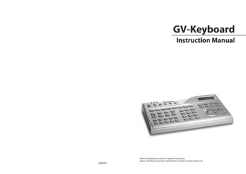
11.IntroductionIntroductionThe GV-Keyboard V3 is used to program and operate GV-Systems and PTZ cameras.Through RS-485 configuration, it can control up to 16 GV-Systems. In addition, throughRS-485 or RS-422 connection, it can set up and control up to 32 PTZ cameras directly withoutmaking any configuration through the GV-System.RXTXP1F1F2P2P3P4F4F3F5RECREC STOP1ALLP5SCHSCH STOPSp eed cusOutAutoPresetOKMenuCancelA- BSp eed-0Key Features Control up to 16 GV-Systems Directly set up and control up to 32 PTZ cameras OSD panel supportedImportant:GV-Keyboard V3 allows you to set up and control PTZ cameras directly without goingthrough GV-Systems. To see the list of PTZ camera protocol supported for this new feature,see Supported PTZ Protocols and Brands, Appendix.GV-Keyboard V3 also supports controlling the PTZ cameras connected to GV-Systems. Forthe PTZ cameras supported by GV-Systems, see Supported PTZ Protocol and Model,Appendix, DVR User’s Manual on the Surveillance System Software DVD.3
1.1 Packing List GV-Keyboard V3 x 1 Power Adaptor (DC Output 12V, 1A) x 1 USB Cable x 1 RJ-11 Cable x 1 Wall Terminal Block x 1 GV-Keyboard V3 Software CD x 11.2 System Requirements Windows XP / Vista / 7 / Server 2008Note: Currently, GV-Keyboard V3 does not support embedded operating systems.1.3 Password Protected FeatureThe GV-Keyboard V3 is protected with a password. When you use the Keyboard for the firsttime, you will need to enter the default password ”0000” to unlock it. You can set an auto locktime to lock the GV-Keyboard V3 after an idle period. The GV-Keyboard V3 can be unlockedonly when you enter the correct password. The default auto lock time is 00, which means theauto lock function is disabled by default. To change the default password and the auto locktime, see “Changing password “and “Setting auto-lock period”, 5. Programming andOperation.4
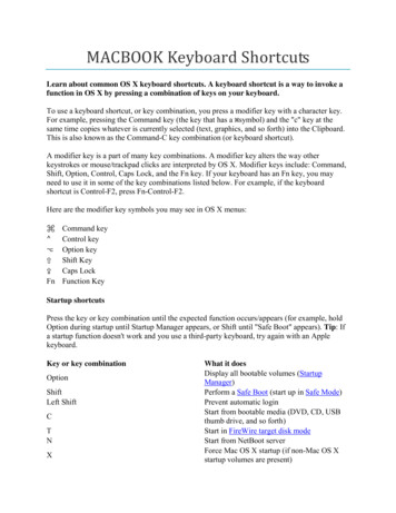
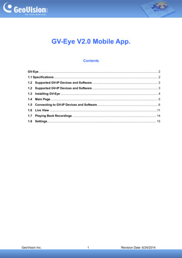
2Overview2. Overview2.1 Keyboard OverviewFigure 1zSection A Yellow POWER LED.RXRed RX LED (Receive).TXGreen TX LED (Transmit).P1Changes DVR ID.P2Select a PTZ camera to control.P3Configures the Keyboard parameters, including password, keybeep and auto-lock period.P4Sets up the PTZ camera settings.P5Displays the firmware version.Locks the Keyboard.F1-8Function keys.5
zSection BLaunches Multicam Surveillance System (Main System).Launches ViewLog.Turns full screen view on/off.Switches the screen divisions.Turns the sound on/off.Plays next events automatically.Starts/Stops recording.Starts/Stops the scheduled recording.Goes to the previous event.Goes to the next event.Plays/Pauses a video event.Rewinds/Pauses a video event.Moves one frame back.Moves one frame forward.Stops a video event.Sets the starting and ending frames for auto playing.Increases playback speed.Decreases playback speed.Switches to the previous screen.6
2OverviewSwitches to the next screen.Numeric buttonsEnters the login password; Selects a specific camera; Changesthe Time Setting in ViewLog.zSection CZooms in the display image of PTZ camera in Main System;Zooms in the display image in ViewLog.Zooms out the display image of PTZ camera in Main System;Zooms out the display image in ViewLog.Increases the focus of PTZ camera in Main System.Decreases the focus of PTZ camera in Main System.Auto Focus.Sets the PTZ camera for auto mode.Moves the PTZ camera to the default position.Moves the PTZ camera to a preset location.Calls up the Login dialog box; Enters the settings; Opens the OSDmenu.Closes the OSD menu; Returns to the previous menu; Calls up themenu to exit Main System or ViewLog.PTZ control; Navigates the display image in ViewLog; Navigatesthe OSD menu; Changes the Time Setting in ViewLog.7
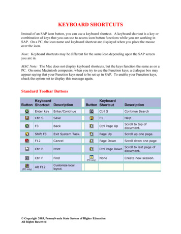
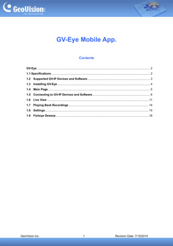
2.1 Rear Panel OverviewFigure 2No NameFunction1JoystickConnects to GV-Joystick for PTZ control.2DC 12VConnects to the power adaptor.3USB1 PortConnects to one GV-System.Through the supplied Wall Terminal Block, the RS-485 port canconnect to:4RS-485Port (RJ-11)zup to 16 GV-Systems by using the assigned RS-485 pins.zup to 32 PTZ cameras by using the assigned RS-485 orRS-422 pins.For details on the pin assignments on the Wall Terminal Block,see 3.3 Wall Terminal Block.568TerminalResistanceResetUsed in the last daisy-chained GV-System.Resets the Keyboard when it does not respond to commands.
3PTZ Camera Installation and Setup3. PTZ Camera Installation and SetupYou can connect up to 32 PTZ cameras to the GV-Keyboard V3 directly without going throughthe GV-System. You can directly control the PTZ cameras by using the PTZ control keys onthe Keyboard. For supported PTZ protocols and brands, see Supported PTZ Protocols andBrands, Appendix.Figure 39
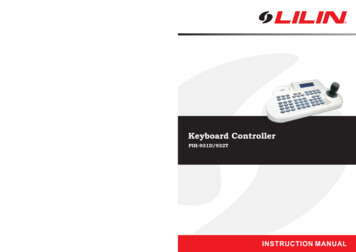
3.1Installing PTZ CamerasYou can connect up to 32 PTZ cameras together, through either a single RS-485 or RS-422cable, to the GV-Keyboard V3. Choosing between RS-485 and RS-422 is depended on thePTZ camera being used. See the illustration below for connections.Items required for connections:zSupplied RJ-11 CablezSupplied Wall Terminal BlockzSupplied Power AdaptorFor RS-485 connection, use Pin-1 and Pin-5 on the Wall Terminal Block to connect the PTZcamera. For RS-422 connection, use Pin-3 and Pin-4 on the Wall Terminal Block to connectthe PTZ camera. For details on the pin assignments on the Wall Terminal Block, see 3.3 WallTerminal Block.RS-485 - / RS-422RS-485 / RS-422 PTZ Camera 1Wall Terminal BlockRJ-11 CablePower AdaptorGV-Keyboard V 3Figure 410PTZ Camera 32
3PTZ Camera Installation and Setup3.2 Setting up PTZ CamerasAfter PTZ camera installation, you have to set up the camera’s number, type, baud rate andPTZ ID through the GV-Keyboard V3.When multiple PTZ cameras are connected together, you need to configure each camera’saddress. Read the manual of the PTZ camera you purchased for address setup. Remembereach camera’s address because they will be the camera’s ID (PTZ ID) in the followingsoftware setup. The PTZ camera’s ID is necessary for the GV-Keyboard V3 to distinguish onecamera from another.Follow the steps below to set up PTZ cameras through the GV-Keyboard V3. You can see thesettings on the LCD display of the GV-Keyboard V3.Figure 5, and type the default password “0000” to unlock the GV-Keyboard V3.1.Press2.Press P4, and press3.to set up a PTZ Type, and press. For details on the PTZPressprotocols, see Supported PTZ Protocols and Brands, Appendix later in this manual.4.Pressto set up the Baud rate, and press5.Pressto set up the PTZ ID, and press6.to select a PTZ cameraAfter the above settings, you can press P2 and pressnumber that you want to control through the GV-Keyboard V3. Alternatively, you canpress P2 and press the number keys to select a camera, for example, pressing 0 andthen 1 for Camera No. 1.to select a PTZ camera number, and press.11
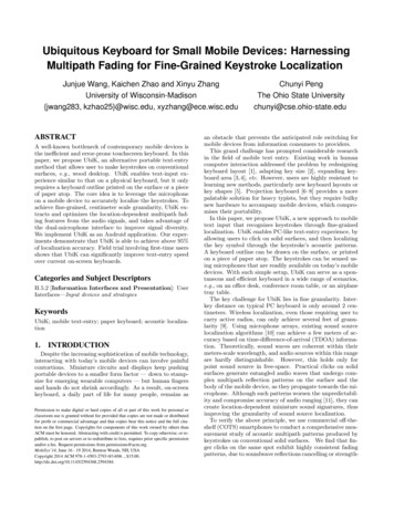
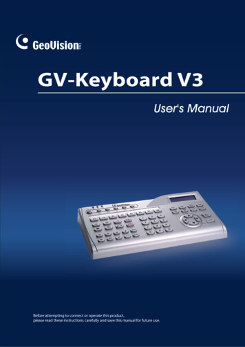
3.3 Wall Terminal BlockWall Terminal BlockGreen 4433 RedYellow 5522 BlackPin FunctionWhite 6611 BlueRJ-11 Cable11PTZ / RS-485 2DVR / RS-485 3PTZ / RS-422-4PTZ / RS-422 5PTZ / RS-485-6DVR / RS-485-6Figure 6Note: Each pin is assigned to its corresponding cable of the unit. To connect the PTZcamera, use Pin-1 and Pin-5 (for RS-485 connection) or Pin-3 and Pin-4 (for RS-422connection). To connect the GV-System, use Pin-2 and Pin-6.12
4Connection to the GV-System4. Connection to the GV-SystemYou can connect the GV-Keyboard V3 to one GV-System by using the supplied USB cable orup to 16 GV-Systems through the RS-485 pins on the Wall Terminal Block.4.1 Connecting to One GV-SystemTo connect GV-Keyboard V3 to one GV-System, use the USB1 port on the GV-Keyboard V3.See the illustration below for connection.Item required for connection:zSupplied USB CableGV-SystemGV-Keyboard V3Figure 7Note: When using the USB cable to connect between the GV-Keyboard V3 and GV-System,you don’t have to connect the GV-Keyboard V3 to a power supply.13
4.2 Connecting to Multiple GV-SystemsTo connect the GV-Keyboard V3 to up to 16 GV-Systems, use the RS-485 port on theGV-Keyboard V3. See the illustration below for connections.Items required for connections:zSupplied RJ-11 CablezSupplied Wall Terminal BlockzSupplied Power AdaptorzRS-485 / RS-232 interface converter, e.g. GV-NET Card, GV-NET/IO Card, GV-Huband GV-COM.Connect one end of the RJ-11 cable to the RS-485 port on the GV-Keyboard V3 and the otherend to the Wall Terminal Block. Then connect the Wall Terminal Block to the RS-485 / RS-232interface converter. For details on the pin assignments on the Wall Terminal Block, see 3.3Wall Terminal Block.Figure 8Note: Because GV-Keyboard V3 uses RS-485 communication that has a distance limitation,the total distance between the GV-Keyboard V3 and the GV-Systems needs to be within 600meters (1968.5 feet).14
44.3Connection to the GV-SystemInstalling USB DriverIf you use the USB port to connect the GV-Keyboard V3 to the GV-System, it is necessary toinstall the USB driver. After you use the USB cable to connect the GV-Keyboard V3 to theGV-System, the Found New Hardware Wizard will automatically detect the device. Ignore theWizard and follow these steps to install the driver:Note: You can only install the drivers by using the attached Software CD, or the SoftwareDVD of GV-System V8.4 or later.1.Insert the Software CD. This window pops up.Figure 92.Select Install Geovision USB Devices Driver. This dialog box appears.Figure 1015
3.Click Install to install the driver. When the installation is complete, this message willappear: Install done!4.Click Exit to close the dialog box.5.To verify that the driver is installed correctly, go to Windows Device Manager. In the Ports(COM & LPT) field, you should see the entry for STM Virtual COM Port.Figure 11Note: Remember the COM port showing in the STM Virtual COM Port entry. It indicatesthe port number that the Keyboard is using.16
4Connection to the GV-System4.4 Starting the Keyboard ApplicationWhen using the GV-Keyboard V3 to control the GV-System, you need to run the followingprogram in the background.1.Run mcamctrl.exe from the GV folder.Figure 122.The Keyboard & Joystick controller dialog box appears.Figure 1317
3.In the Device drop-down list, select the COM port that the GV-Keyboard V3 is connectedto. The COM port number can be found in the Windows Device Manager (Figure 11).4.Click . You can start to control the GV-System by using the GV-Keyboard V3 now.The controls in the Keyboard & Joystick controller dialog box:NameDescriptionDVR IDSelect the desired DVR ID for connection.DVR NameGives the DVR a descriptive name.Startup typeSelect Manual or Automatic to choose whether to run the controllerat next startup or not.PTZ SpeedAdjusts PTZ speed.Monopoly ModeAssign the Keyboard to control a specific monitor and set up thecontrol modeDevice 1-8Select the COM port connecting to the Keyboard. Find the COMport number the Keyboard is using in the Ports field of WindowsDevice Manager. See Step 5 of 4.3 Installing USB Driver.Select the Keyboard to define F1-F8 functions. Starts the service. Stops the service.F1 - F8Defines eight function keys on the Keyboard to control outputmodules, display layout, PTZs, cameras and etc.Prints out a label for the eight function keys.Note: You can connect up to 8 units of GV-Keyboard V3 to one GV-System. When multipleunits of GV-Keyboard V3 are connected, be sure to verify the driver installation of eachGV-Keyboard V3 in the Ports field of Windows Device Manager. If the driver of any deviceis not installed properly, select Install or Remove GeoVision GV-Series Driver on theSoftware DVD to re-install it. After selecting the COM port that each GV-Keyboard V3 isconnected to, you can start to use the drop-down listselect a device to configure.18at upper left corner to
44.4.1Connection to the GV-SystemDefining Eight Function KeysF1 - F8 options allow you to assign these features to the eight function keys on the Keyboard: Output Control Display Layout PTZ Preset Go PTZ Auto Camera Select Start/Stop Camera Scan Matrix Switch Digital Matrix Spot Monitor TV QuadNote: For the PTZ Preset Go and PTZ Auto functions, you must map the PTZ camera first inthe GV-System.Figure 1419
4.4.2Printing Function Key LabelsThe Print Memo option allows you to print out the labels for the eight function keys (F1 - F8)so that you can paste them on the Keyboard for instant reference.1.Click the Printer icon. This displays the Printer Memo dialog box.2.Under every field from F1 to F8, type the information that you want to print on the labels.The words you type will also appear on Preview fields for print preview.3.Click Print.Figure 1520
4Connection to the GV-System4.5 Using the Keyboard for LoginIf you want to use the GV-Keyboard V3 to log into the GV-System instead of using the generalkeyboard and mouse, you must export the login ID and password from the GV-System first.Note the IDs and passwords configured can ONLY be composed of digits.1.Click the Configure button, select General Setting, select Password Setup and selectLocal Account Edit. The Password Setup dialog box appears.Figure 162.Select a user from the user list, and select Export this ID for IR Remote Control(GV-Keyboard) to export the ID and Password to the Login dialog box. Click OK.After you complete the above setting, you can start to use the GV-Keyboard V3 to log into theGV-System. Clickto log into the GV-System. You will see the exported ID in the IDdrop-down list of the Login dialog box. Clickand clickto select the user’s ID. Type the password.21
4.6 Using the Keyboard with Multiple MonitorsYou can use the GV-Keyboard V3 to control additional TV or spot monitors which are set up todisplay pop-up alert and page scan by using Digital Matrix, Spot Monitor or Quad SpotMonitor (TV Quad) function.The GV-Keyboard V3 helps you quickly switch control between multiple monitors if any ofthem displays an event that catches your attention through pop-up alert or page scan.There are two modes for the GV-Keyboard V3 applications with multiple monitors:Non-Monopoly ModeIn this mode, one GV-Keyboard V3 can control up to 8 monitors, or up to 8 units ofGV-Keyboard V3 can work with up to 8 monitors together. Because multiple keyboards mayinterfere with each other on the same monitor or the GV-System, it is suggested to apply thismode when the GV-System and additional monitors are placed close to each other.Monopoly ModeIn this mode, each GV-Keyboard V3 or GV-Joystick can only control one assigned monitor.This mode can prevent multiple devices from interfering with each other on the GV-System;therefore it is suggested to apply this mode when the GV-System and additional monitors areplaced at separate places with different operators.22
44.6.1Connection to the GV-SystemNon-Monopoly ModeIn the Non-Monopoly mode, you can switch control between GV-System and additionalmonitors by pressing a defined Function Key on the GV-Keyboard V3. Up to 8 units ofGV-Keyboard V3 can connect to one GV-System, and therefore you may define FunctionKeys on each GV-Keyboard V3 to quickly access additional monitors.It is required to run mcamctrl.exe in the background when you use the GV-Keyboard V3 forscreen display control.1.Run mcamctrl.exe from GV folder. The Keyboard & Joystick controller dialog boxappears (Figure 13).2.In the Device field, select the COM port connecting to each GV-Keyboard V3. The COMport number can be found in Windows Device Manager (Figure 11).3.Use the drop-down listconfigured.4.Click a Function Key to set up quick access to an additional monitor. This dialog boxappears.at upper left corner to select a device to beFigure 175.Select Digital Matrix, Spot Monitor, or TV Quad according to your configuration for thatmonitor.6.Select a specific monitor number for quick access.7.Repeat Step 3 to 6 to configure another GV-Keyboard V3.Note:1.When multiple units of GV-Keyboard V3 or GV-Joysticks are connected, be sure to verifythe driver installation of each GV-Keyboard V3 or GV-Joystick in the Ports field ofWindows Device Manager. If the driver of any device is not installed properly, selectInstall or Remove GeoVision GV-Series Driver on the Software DVD to re-install it.2.Function Keys are not available on GV-Joystick; therefore the Non-Monopoly mode isonly for GV-Keyboard V3.23
Controlling Screen Display on Additional MonitorsThe following picture illustrates the keys of the GV-Keyboard V3 that you can use for screendisplay control on additional monitors.To resume the earlier screen display after pressing a Function Key to access the additionalmonitor, press the same function key again.Function keysdefined for quickaccess to anadditional monitorPTZ Control keysexcept the Autoand Home keysChannel DivisionkeyNumber, Page Upand Page DownkeysDVR Control KeysFigure 18Note: The PTZ control only works in Single View.24
44.6.2Connection to the GV-SystemMonopoly ModeIn Monopoly Mode, each GV-Keyboard V3 or GV-Joystick can only control one assignedmonitor. This mode is recommended when multiple monitors are placed at separate locations.The diagram below illustrates the wiring of 8 units of the combination of GV-Keyboard V3 andGV-Joystick. Because of the long distance additional monitors may cover, use RS-485 cablesto connect each GV-Keyboard V3 to RS-485 converters (e.g. GV-Hub and GV-COM) and thenconnect these RS-485 converters to the GV-System through USB port.Figure 19Assigning a GV-Keyboard V3 or GV-Joystick to an Additional Monitor1.Repeat Steps 1 to 3 in Non-Monopoly Mode mentioned earlier.2.Click the Setting button of Monopoly Mode.Figure 2025
3.Select the Device tab for the GV-Keyboard V3 that you want to assign a monitor for.Figure 214.Select Used for a specific monitor.5.Under Select Target section, select Digital Matrix, Spot Monitor, TV Quad or Matrixaccording to the configuration of that monitor, and select the specific monitor numberfrom the drop-down list.6.Under Control Mode section, select between using GV-Keyboard V3 alone or withGV-Joystick (Control with GV-KB or GV-KB connected with GV-Joystick) and usingGV-Joystick alone (Control with GV-Joystick).26
4Connection to the GV-SystemControlling Screen Display on Additional Monitors For users of GV-Joystick only:Press Previous Camera or Next Camera to select and control a PTZ camera on theadditional monitor. To return to the previous screen display such as a pop-up alert or pagescan, keep pressing Previous Camera until reaching the camera prior to the first PTZ cameraor Next Camera until reaching the camera after the last PTZ camera. For users of GV-Keyboard V3 or GV-Keyboard V3 with GV-Joystick:Press Switch Channel Division, Previous Screen, Next Screenor enter the desired camera number to control the assigned camera (PressPrevious Camera or Next Camera on the GV-Joystick to get the same effect). Press Cancelto return to the previous screen display such as a pop-up alert or page scan.The following picture illustrates the keys of the keyboard that you can use for screen displaycontrol in the Monopoly Mode.PTZ Control keysexcept the Autoand Home keysChannel DivisionkeyNumber, Page Upand Page DownkeysFigure 2227
5.Programming and OperationFunctionGetting startedLaunching MainProcedurePress any key, and enter a password.(The default password is 0000.)1.Press2.When the message "Multicam System-Please Login!" appearson the screen, pressSystemLaunching ViewLog.to open the Login dialog box.3.Select a valid ID, enter a password, and press1.Press2.When the Privilege Confirmation dialog box appears, select a.valid ID, enter a password, and pressChanging DVR IDPress P1, and enter a two-digit DVR ID.Selecting a PTZPress P2, and presscameracontrol.Setting up PTZcameras.to select a PTZ camera that you want toPress P4 to set up PTZ cameras.For details on the PTZ camera setup, see 3.2 Setting up PTZCameras.1.Changing password.Press P3, enter a password, and pressto browse theoptions on the LCD display.2.When "Password Change" appears, pressand enter afour-digit password.1.to browse theoptions on the LCD display.Disabling/Enablingkey beepPress P3, enter a password, and press2.When "Audio Setting" appears, pressand pressto enable/disable the key beep.1.Press P3, enter a password, and pressto browse theoptions on the LCD display.Setting auto-lockperiod2.When "Auto Time Lock" appears, pressand enter an idleperiod after which the Keyboard is automatically locked.* The Keyboard can be used only when the correct password isentered.28
51.PressProgramming and Operation. The message "A To B Mode (Set A)" appears onthe screen.Setting A to B framefor auto-playing2.Pressagain. The message "A To B Mode (Set B)"appears. ViewLog starts playing the set frames A to Brepeatedly.* To stop the playing, press. The message "A To BMode (Cancelled)” will appear.29
6.On-Screen Display MenusIn Main System and ViewLog modes, you can pressto call up the on-screen display(OSD) menus.6.1 The OSD Menu in Main SystemFigure 23Screen DivisionChanges the screen divisions.Input DeviceDisplays all or several input module panels.Output DeviceForces output devices.PTZ CameraEnables/Disables PTZ camera, Preset Go, Auto (Auto Pan), AF (AutoFocus) and Hide PTZ Panel.MonitorStarts/Stops monitoring all or some cameras.ScheduleEnables/Disables the schedule.Camera ScanEnables/Disables the rotation through screen divisions.NetworkEnables/Disables remote applications, including Modem Server, TCPServer, Multicast Server, Connect to VSM, Twin Server, WebCam Serverand Connect to Center V2.POSEnables/Disables/Switches multiple POS Live Views.1.Press2.Select POS on OSD menu again, select View Mode Switch and pressand pressto enable POS1 Live View.to enable switching between Show All or Hide All POS Live30
6 On-Screen Display MenusViews.3.Enter POS again and you can switch to Show All or Hide All to showor hide all POS Live Views or disable the View Mode Switch function.You can only set up one function every time you enter POS. For example, ifyou have enabled Show All of the POS Live Views but now want to disablePOS1 and POS2, you will have to enter POS to disable POS1 and thenenter POS again to disable POS2.Spot MonitorConfigures settings such as scan and zoom by selecting Spot1 to configurechannels 1 to 16 or Spot2 to configure channels 17 to 32.6.1.1Changing the Main System OSD OptionsTo change the Main System OSD options with the Keyboard, follow the steps below:1.Press the OK/Menu button to open the OSD (Figure 1).2.Use the direction buttons to select a menu you want.3.Press the OK/Menu button to open the menu.4.Use the direction buttons to select a menu option, and then press the OK/Menu buttonto change the setting.ORSimply press the OK/Menu button to enable or disable an option in the case of Scheduleand Camera Scan.31
6.2The OSD Menu in ViewLogFigure 24Video Event SearchLocates a video event.1.Press theandbuttons to move back and forth along the OSDtime to select a unit of time. (Month/Date/Year Hr.:Min.:Sec.)2.Use the numeric buttons to enter a desired time or pressandto change the display time.3.Press the OK/Menu button to view the search result.If the event at the specified time can't be located, the previous or next videoevent available will be displayed.View ModeChanges the view modes, including Single View, Thumbnail View, QuadView and Multi View.Playback ModeChanges the playback modes, including Real Time, Frame by Frame andJust Key Frame.6.2.1Changing the ViewLog OSD OptionsTo change the ViewLog OSD options with the Keyboard, follow the steps below:1.Press the OK/Menu button to open the OSD (Figure 1).2.Use the direction buttons to select a menu you want.3.Press the OK/Menu button to open the menu.4.Use the direction buttons to select a menu option, and then press the OK/Menu button tochange the setting.32
77.Shortcut Key Conflict TestShortcut Key Conflict TestThis test checks whether the Keyboard keys are conflicting with certain shortcut keys o
4 1.1 Packing List GV-Keyboard V3 x 1 Power Adaptor (DC Output 12V, 1A) x 1 USB Cable x 1 RJ-11 Cable x 1 Wall Terminal Block x 1 GV-Keyboard V3 Software CD x 1 1.2 System Requirements Windows XP / Vista / 7 / Server 2008 Note: Currently, GV-Keyboard V3 does not support embedded operating systems. 1.3 Password Protected Feature