Transcription
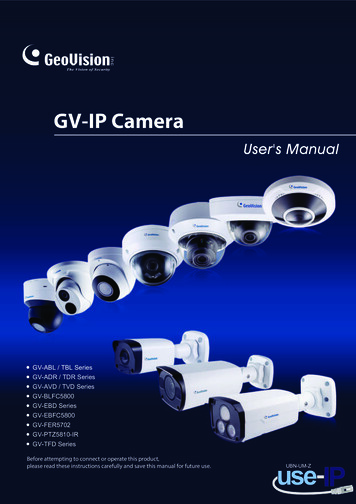
GV-IP CameraUser's ManualGV-ABL / TBL SeriesGV-ADR / TDR SeriesGV-AVD / TVD SeriesGV-BLFC5800GV-EBD SeriesGV-EBFC5800GV-FER5702GV-PTZ5810-IRGV-TFD SeriesBefore attempting to connect or operate this product,please read these instructions carefully and save this manual for future use.UBN-UM-Z
2022 GeoVision, Inc. All rights reserved.Under the copyright laws, this manual may not be copied, in whole or in part,without the written consent of GeoVision.Every effort has been made to ensure that the information in this manual isaccurate. GeoVision, Inc. makes no expressed or implied warranty of any kindand assumes no responsibility for errors or omissions. No liability is assumedfor incidental or consequential damages arising from the use of the informationor products contained herein. Features and specifications are subject tochange without notice.GeoVision, Inc.9F, No. 246, Sec. 1, Neihu Rd.,Neihu District, Taipei, TaiwanTel: 886-2-8797-8377Fax: ks used in this manual: GeoVision, the GeoVision logo and GVseries products are trademarks of GeoVision, Inc. Windows is the registeredtrademark of Microsoft Corporation.May 2022Scan the following QR codes for product warranty and technical supportpolicy:[Warranty][Technical Support Policy]
PrefaceWelcome to the GV-IP Camera User’s Manual.The features described in the manual vary among camera models and versions. Somefeatures may not be available in your camera.This Manual is designed for the following models:ModelModel NumberGV-EBD2702 / 2704GV-EBD4700 / 4701 / 4704 / 4711 / 4712 / 4813IR Eyeball DomeGV-EBD8700 / 8711 / 8800 / 8813GV-EBFC5800GV-ABL2701 Series / 2702 / 2703 SeriesGV-ABL4701 Series / 4703 / 4711 / 4712GV-ABL8712Bullet IP CameraGV-TBL2703 Series / 2705 / 4700 / 4703 / 4705 / 4710 /4711 / 4810GV-TBL8710 / 8804 / 8810GV-BLFC5800Mini Fixed IP DomeGV-TFD4700 / 4800GV-ADR2701 / 2702GV-ADR4701 / 4702GV-TDR2700 / 2702 / 2704Mini Fixed Rugged IP DomeGV-TDR4700 Series / 4702 Series / 4703 Series / 4704Series / 4803 SeriesGV-TDR8805GV-AVD2700GV-AVD4710Vandal Proof IP DomeGV-AVD8710GV-TVD4700 / 4710 / 4711 / 4810GV-TVD8710 / 8810IR Fisheye Rugged IPGV-FER5702CameraIR Mini PTZ CameraGV-PTZ5810-IRi
ContentsNaming Definition .viNote for Connecting to GV-VMS / DVR / NVR .viiNote for Installing Camera Outdoor .viiNote for Powering the Camera .viiNote for Face Detection .viiiNote for People Counting .ixChapter 1Introduction .11.1 GV-EBD Series and GV-EBFC5800 . 11.1.1 Packing List. 21.1.2 Optional Accessories . 21.1.3 Overview . 41.1.3.1 GV-EBD2702 / 2704 / 4700 / 4701 / 4704 / 8700 / 8800 andGV-ENFC5800 . 41.1.3.2 GV-EBD4711 / 4712 / 4813 / 8711 / 8813 . 51.1.4 Installation . 61.1.4.1 GV-EBD2702 / 2704 / 4700 / 4701 / 4704 / 8700 / 8800 andGV-EBFC5800 Standard Installation . 61.1.4.2 GV-EBD4711 / 4712 / 4813 / 8711 / 8813 Standard Installation . 91.1.5 Optional Installation.121.1.5.1 GV-Mount211P .121.1.5.2 GV-Mount212P .171.1.5.3 GV-Mount420 GV-Mount211P .211.1.5.4 GV-Mount212P GV-Mount107 .241.2 GV-ABL / TBL Series & GV-BLFC5800.261.2.1 Packing List.271.2.2 Optional Accessories .271.2.3 Overview .291.2.3.1 GV-ABL2701 / 2703 / 4701 / 4703 & TBL2703 / 2705 / 4703 .291.2.3.2 GV-ABL2702 / 4711 / 4712 / 8712, TBL4700 / 4705 / 4710 / 4711 /8710 / 8804 / 8810, and BLFC5800 .301.2.4 Installation .311.2.5 Optional Installation.34ii
1.2.5.1 GV-Mount502 .361.2.5.2 GV-Mount503 .381.2.5.3 GV-Mount420 GV-Mount503 .401.2.5.4 GV-Mount504 .421.3 GV-ADR / TDR Series .441.3.1 Packing List.461.3.2 Optional Accessories .461.3.3 Overview .491.3.4 Installation .501.3.5 Optional Installation .531.3.5.1 GV-Mount211P .531.4 GV-AVD / TVD Series .571.4.1 Packing List.581.4.1.1 GV-TVD4711 .581.4.1.2 GV-AVD / TVD Series.591.4.2 Optional Accessories .601.4.3 Overview .621.4.3.1 GV-AVD2700 / 4710 / 8710, GV-TVD4700 / 4710 / 4810 / 8710 /8810.621.4.3.2 GV-TVD4711 .631.4.4 Installation .641.4.4.1 GV-AVD2700 / 4710 / 8710, GV-TVD4700 / 4710 / 4810 / 8710 /8810.641.4.4.2 GV-TVD4711 .661.4.5 Optional Installation.671.4.5.1 GV-Mount211-2 .681.4.5.2 GV-Mount212-2 .701.4.5.3 GV-Mount420 GV-Mount211-2 .731.4.5.4 GV-Mount606 .741.5 GV-TFD Series .761.5.1 Packing List.761.5.2 Optional Accessories .771.5.3 Overview .781.5.3.1 GV-TFD4700 / 4800 .781.5.4 Installation .791.5.4.1 GV-TFD4700 / 4800 .791.5.5 Optional Installation.80iii
1.6 GV-FER5702 .811.6.1 Packing List .811.6.2 Optional Accessories .821.6.3 Overview.831.6.3.1 GV-FER5702 .831.6.4 Installation .841.6.5 Optional Installation .861.7 GV-PTZ5810-IR .871.7.1 Packing List .871.7.2 Optional Accessories .881.7.3 Overview.891.7.3.1 GV-PTZ5810-IR .891.7.4 Installation .901.7.5 Optional Installation .921.8 System Requirements.931.9 Waterproofing the Cable .94Chapter 2Accessing the Camera .962.1 Installing on a Network.962.1.1 Looking up the Dynamic IP Address and Logging In .972.1.2Configuring the IP Address .982.2 Accessing Live View .992.2.1 Digital Zoom .1012.2.2 Start Recording .1012.3 PTZ Control Panel .1022.3.1 Accessing the PTZ Control Panel.1022.3.2 Setting Presets.1042.3.3 Setting a Patrol .1052.4 Playing Back Recorded Videos .1092.4.1 Recording Download .110Chapter 33.1Administrator Mode .111Common .1143.1.1 Basic Info .1143.1.2 Local Parameters .1153.2Network .1173.2.1 Network.1173.2.2 DNS .118iv
3.2.3 Port .1193.2.4 DDNS.1203.2.5 E-mail.1223.2.6 SNMP .1233.2.7 802.1x .1243.2.8 QoS .1253.3 Video & Audio .1263.3.1 Video.1263.3.2 Snapshot.1283.3.3 Audio.1303.3.4 ROI .1313.3.5 Media Stream.1323.4PTZ.1343.4.1 Basic Settings .1343.4.2 Home Position.1353.4.3Limit .1353.4.4 Remote Control .1363.4.5 Patrol .1373.4.6 Orientation .1383.5 Image .1393.5.1 Image .1393.5.2 OSD .1443.5.3 Privacy Mask.1463.6Intelligent .1473.6.1 Smart Settings .1473.6.1.1Cross Line .1493.6.1.2 Intrusion .1523.6.1.3 Object Removed .1553.6.1.4 Object Left Behind .1563.6.1.5Defocus .1573.6.1.6Scene Change .1583.6.1.7Face Detection .1593.6.1.8People Counting .1623.6.1.9Human Body Detection .1643.6.2.10Enter Area / Leave Area .1653.6.2.11Crowd Density Monitoring .1673.6.2 Advanced Settings .168v
3.7Events .1693.7.1 Motion Detection .1693.7.2 Tampering Alarm .1713.7.3 Audio Detection .1723.7.4 Alarm Input.1733.7.5 Alarm Output .1743.7.6 One-Key Shielding Linkage .1753.8 Storage .1763.8.1 Formatting Storage .1763.8.2 FTP .1793.8.3 Backing Up Storage .1813.9 Security.1823.9.1 User .1823.9.2 Network Security .1833.10 System.1863.10.1 Time .1863.10.2 Server .1883.10.3 Maintenance .1883.10.4 Network Diagnosis .1903.10.5 Log .1903.10.6 Ports and Devices .191Chapter 4Advanced Applications .1924.1 Upgrading System Firmware.1924.1.1 Using the Web Interface .1934.1.2 Using GV-IP Device Utility.1944.2Restoring to Factory Default Settings .195Chapter 55.1DVR / NVR / VMS .196Setting Up IP Cameras on GV-DVR / NVR .1975.2 Setting Up IP Cameras on GV-VMS .200vi
Appendix .202A.RTSP Multicast Protocol Support .202B.RTSP Protocol Support .202C.HTTP Protocol Support .202D.Compatible Versions of GV-VMS / DVR / NVR.203E.GV-Mount Dimensions .206F. GV-Mount300-2 / 310-2 .209G. Screw Position Chart.211H.Note for Fisheye Camera with IR LED .212I.Retrieve Camera’s Password.213vii
Naming DefinitionGV-DVR / NVRGeoVision Analog and Digital Video Recording Software. The GVDVR also refers to GV-Multicam System or GV-Hybrid DVR.GV-VMSGeoVision Video Management System for IP cameras.vi
Note for Connecting to GV-VMS / DVR / NVRThe GV-IPCAM in this Manual is designed to work with and record on GV-VMS / DVR / NVR,a video management system. Once the camera is connected to the GV-VMS / DVR / NVR, the resolution set on theGV-VMS / DVR / NVR will override the resolution set on the camera’s Web interface.You can only change the resolution settings through the Web interface when theconnection to the GV-VMS / DVR / NVR is interrupted. The login password of the camera cannot contain the character “&” or any whitespacewhen connecting to GV-VMS. The Video Analytic features under Intelligent (see 3.5 Intelligent) cannot be integratedwith GV-VMS / DVR / NVR.Note for Installing Camera OutdoorWhen installing the camera outdoor, be sure that:1.The camera is set up above the junction box to prevent water from entering the cameraalong the cables.2.Any PoE, power, audio and I/O cables are waterproofed using waterproof silicon rubberor the like.3.The screws are tightened and the cover is in place after opening the camera cover.Note for Powering the CameraThe camera is powered by PoE or a power adapter. If you want to power the camera usingthe power connector, an optional power adapter is required.vii
Note for Face DetectionTo use the camera’s built-in face detection feature (see 3.5.1.7 Face Detection), which isonly supported by certain models, it is recommended to install the camera according to thecriteria listed below:Surveillance Condition The camera shall be installed at a site with uniform, sufficient lighting, where theface(s) to be detected are fully illuminated.Example of Recommended SceneExample of Non-recommended SceneCamera Position The camera shall be mounted at a recommended height of 2.5 3 m (8.2 9.84 ft). The camera shall be mounted with a recommended depression angle of around 10 . The camera shall be positioned so that the face(s) to be detected are directly alignedwith the lens of the camera, with a horizontal deviation of no greater than 30 , avertical deviation of no greater than 15 and a face size of at least 120 pixels.Horizontal lineDepression angle αOptical axis ofthe cameraPedestrian walking direction(straight along the center ofthe ground)Horizontal surveillance distanceviiiDevice mounting heightSurveillancearea width
Note for People CountingTo use the camera’s built-in people counting feature (see 3.5.1.8 People Counting), which isonly supported by certain models, it is recommended to install the camera according to thecriteria listed below:Surveillance Condition The camera shall be installed at a site with uniform, sufficient lighting, where theperson(s) to be counted are fully illuminated. The camera shall be installed at an entrance or exit with an ideal width of 1 4 m(3.28 13.12 ft), where the persons(s) to be counted move toward the lens of thecamera in single file.Example of Recommended SceneExample of Non-recommended SceneCamera Position The camera shall be mounted at a recommended height of 3 5 m (9.84 16.4 ft). The camera shall be mounted with a recommended depression angle of 70 80 . The camera shall be positioned so that the person(s) to be counted face toward thelens of the camera and are displayed on the image with a shoulder size of between120 160 pixels.Horizontal lineDepression angle αOptical axis ofthe cameraPedestrian walking direction(straight along the center ofthe ground)Horizontal surveillance distanceixDevice mounting heightSurveillancearea width
1IntroductionChapter 1 Introduction1.1 GV-EBD Series and GV-EBFC5800The H.265 Eyeball Dome is an outdoor, network camera equipped with an automatic IR-cutfilter and IR LEDs for day and night surveillance. For GV-EBFC5800, it’s equipped with fullcolor smart warm LEDs for accurate day and night surveillance. The camera adheres to IP67standards for dust / water protection and supports H.265 video codec to achieve bettercompression ratio while maintaining high quality image at reduced network bandwidths. Withits WDR Pro (WDR for GV-EBD2702), it can process scenes with contrasting intensity oflights and produce clear image.For GV-EBD4711 / 4712 / 4813 / 8711 / 8813, with their motorized lenses, the user canzoom and focus the camera from the Web interface. Certain camera models also providebuilt-in micro-SD card slot for local storage.Model No.GV-EBD2702GV-EBD2704GV-EBD4700GV-EBD4701Fixed 4712GV-EBD4813Motorizedvarifocal lensGV-EBD8711GV-EBD8813GV-EBFC5800Fixed lensSpecificationsFixed Iris, f: 2.8 mm, F/1.8,M12 Lens MountFixed Iris, f: 2.8 mm, F/2.0,M12 Lens MountFixed Iris, f: 2.8 mm, F/1.8,M12 Lens MountFixed Iris, f: 2.8 mm,F/2.0, M12 Lens MountFixed Iris, f: 2.8 mm,F/1.6, M12 Lens MountDescription2 MP, H.265, Low Lux,WDR2 MP, H.265, Low Lux,WDR Pro4 MP, H.265, Super LowLux, WDR ProFixed Iris, f: 2.8 mm,F/2.0, M12 Lens Mount8 MP, H.265, Low Lux,WDR ProFixed Iris, f: 2.7 12 mm,F/1.4, Ø 12 mm Lens MountFixed Iris, f: 2.8 12 mm,F/1.6, Ø 12 mm Lens Mount4 MP, H.265, Super LowLux, WDR ProFixed Iris, f: 2.7 13.5 mm,F/1.2, Ø 12 mm Lens MountFixed Iris, f: 2.8 12 mmF/1.5, Ø 12 mm Lens MountFixed Iris, f: 2.8 12 mm,F/1.6, Ø 12 mm Lens Mount8 MP, H.265, Super LowLux, WDR ProFixed Iris, f: 2.8 mm, F/1.0,M12 Lens Mount5 MP, H.265,Super Low Lux, WDR Pro,Warm LED1
1.1.1 Packing List H.265 Target Eyeball Dome Screw Kit Drill Template Paster Waterproof Rubber Set Download Guide1.1.2 Optional AccessoriesOptional accessories can expand the capabilities and versatility of your camera. Contact yourdealer for more information.Model NumberNameDetailsGV-Mount107Pendant Bracket(must be used withGV-Mount212P)Dimensions: Ø 120 x 334 mm (Ø4.72” x 13.15”)Weight: 0.74 kg (1.63 lb)GV-Mount211PWall Mount and Junction BoxDimensions: 233 x 125 x 125 mm(9.2” x 4.9” x 4.9”)Weight: 1 kg (2.2 lb)GV-Mount212PWall Box MountDimensions: Ø 126 x 36 mm (Ø5.0” x 1.4”)Weight: 0.22 kg (0.48 lb)2
1IntroductionGV-Mount300-2Convex Corner MountDimensions: 137 x 233 x 160 mm(5.4” x 9.17” x 6.3”)Weight: 1.65 kg (3.64 lb)GV-Mount310-2Concave Corner MountDimensions: 111.2 x 369.9 x 210mm (2.6” x 11.4” x 6.6”)Weight: 1.65 kg (3.64 lb)GV-Mount420(must be used withGV-Mount211P)Pole Mount BracketDimensions: Ø 120 x 120 x 53.4mm (Ø 4.7” x 4.7” x 2.1”)Weight: 0.45 kg (0.99 lb)Steel Strap Diameter: Ø 67 127mm (Ø 2.6” 5”)GV-Mount704(must be used withGV-Mount107)Extension TubeDimensions: Ø 3.5 x 10 or 20 or 30or 50 cm (Ø 1.38 x 3.9 or 7.9 or11.8 or 19.7”)Weight: 225 g or 360 g or 500 g or780 g (0.5 lb or 0.79 lb or 1.1 lb or1.72 lb)GV-PA191Power over Ethernet (PoE)AdapterGV-PA191 is a Power overEthernet (PoE) adapter designedto provide power to the IP devicethrough a single Ethernet cable.GV-POE SwitchGV-POE Switch is designed to provide power along with networkconnection for IP devices. GV-POE Switch is available in variousmodels with different numbers and types of ports.Power AdapterContact our sales representatives for the countries and areassupported.3
1.1.3 Overview1.1.3.1 GV-EBD2702 / 2704 / 4700 / 4701 / 4704 / 8700 / 8800 and GVEBFC5800Figure 1-1No. Description1Bottom ring2Housing3Lens4Infrared indicator / Warm LEDs (GV-EBFC5800 only)5Power connector (DC 12 V)6Ethernet connector / PoEMicro SD card slot (GV-EBD2704 / 4701 / 4704 / 8800 and GVEBFC5800 only)Microphone (GV-EBD2704 / 4701 / 4704 / 8800 and GVEBFC5800 only)784
1Introduction1.1.3.2 GV-EBD4711 / 4712 / 4813 / 8711 / 8813Figure 1-2No.Description1Bottom ring2Housing3Microphone4Lens5Power connector (DC 12 V)6Ethernet connector / PoE7Micro SD card slot and default button compartment8Default button9Micro SD card slotNote: If the default button doesn’t respond after pressing for 15 seconds, reboot thecamera and try again within 10 minutes of rebooting.5
1.1.4 InstallationThe Target Eyeball Dome is designed for outdoors. With the standard package, you caninstall the camera on the ceiling. Alternatively, you can purchase optional mountingaccessories to mount the dome on a wall.Below are the instructions for Ceiling Mount. There are two kinds of Ceiling Mount:Concealed Installation and Open Instal
GV-Multicam System. or . GV-Hybrid DVR. GV-VMS. GeoVision Video Management System for IP cameras. vii . Note for Connecting to GV-VMS / DVR / NVR . The GV-IPCAM in this Manual is designed to work with and record on GV-VMS / DVR / NVR, a video management system.