Transcription
AN4488Application noteGetting started with STM32F4xxxx MCUhardware developmentIntroductionThis application note is intended for system designers who require a hardwareimplementation overview of the development board features, such as the power supply, thepackage selection, the clock management, the reset control, the boot mode settings and thedebug management. It shows how to use the high-density performance line STM32F4xxxxproduct families and describes the minimum hardware resources required to develop anSTM32F4xxxx application.Detailed reference design schematics are also contained in this document with descriptionsof the main components, interfaces and modes.Table 1. Applicable productsTypePart NumberSTM32F401xB / STM32F401xCSTM32F401xD / STM32F401xESTM32F405xx / STM32F407xxMicrocontrollersSTM32F415xx / STM32F417xxSTM32F427xx / STM32F429xxSTM32F437xx / STM32F439xxJune 2014DocID026304 Rev 11/41www.st.com
ContentsAN4488Contents1Reference documents . . . . . . . . . . . . . . . . . . . . . . . . . . . . . . . . . . . . . . . . 62Power supplies . . . . . . . . . . . . . . . . . . . . . . . . . . . . . . . . . . . . . . . . . . . . . 72.132.1.2Battery backup . . . . . . . . . . . . . . . . . . . . . . . . . . . . . . . . . . . . . . . . . . . . . 72.1.3Voltage regulator . . . . . . . . . . . . . . . . . . . . . . . . . . . . . . . . . . . . . . . . . . . 82.3Reset & power supply supervisor . . . . . . . . . . . . . . . . . . . . . . . . . . . . . . . 102.3.1Power on reset (POR) / power down reset (PDR) . . . . . . . . . . . . . . . . . 102.3.2Programmable voltage detector (PVD) . . . . . . . . . . . . . . . . . . . . . . . . . 102.3.3System reset . . . . . . . . . . . . . . . . . . . . . . . . . . . . . . . . . . . . . . . . . . . . . 112.3.4PDR ON circuitry example . . . . . . . . . . . . . . . . . . . . . . . . . . . . . . . . . . 122.3.5Regulator OFF mode . . . . . . . . . . . . . . . . . . . . . . . . . . . . . . . . . . . . . . . 142.3.6Regulator ON/OFF and internal reset ON/OFF availability . . . . . . . . . . 15Package . . . . . . . . . . . . . . . . . . . . . . . . . . . . . . . . . . . . . . . . . . . . . . . . . . 163.1Package Selection . . . . . . . . . . . . . . . . . . . . . . . . . . . . . . . . . . . . . . . . . . 163.2Pinout Compatibility . . . . . . . . . . . . . . . . . . . . . . . . . . . . . . . . . . . . . . . . . 183.2.1Compatibility within STM32F4x family . . . . . . . . . . . . . . . . . . . . . . . . . . 193.2.2Compatibility with STM32F1x and STM32F2x families . . . . . . . . . . . . . 20Alternate Function mapping to pins . . . . . . . . . . . . . . . . . . . . . . . . . . . . . 22Clocks . . . . . . . . . . . . . . . . . . . . . . . . . . . . . . . . . . . . . . . . . . . . . . . . . . . . 234.24.3HSE OSC clock . . . . . . . . . . . . . . . . . . . . . . . . . . . . . . . . . . . . . . . . . . . . 234.1.1External source (HSE bypass) . . . . . . . . . . . . . . . . . . . . . . . . . . . . . . . . 244.1.2External crystal/ceramic resonator (HSE crystal) . . . . . . . . . . . . . . . . . 24LSE OSC clock . . . . . . . . . . . . . . . . . . . . . . . . . . . . . . . . . . . . . . . . . . . . . 254.2.1External source (LSE bypass) . . . . . . . . . . . . . . . . . . . . . . . . . . . . . . . . 254.2.2External crystal/ceramic resonator (LSE crystal) . . . . . . . . . . . . . . . . . . 25Clock security system (CSS) . . . . . . . . . . . . . . . . . . . . . . . . . . . . . . . . . . 26Boot configuration . . . . . . . . . . . . . . . . . . . . . . . . . . . . . . . . . . . . . . . . . 275.12/41Independent A/D converter supply and reference voltage . . . . . . . . . . . . 7Power supply schemes . . . . . . . . . . . . . . . . . . . . . . . . . . . . . . . . . . . . . . . 84.152.1.12.23.34Introduction . . . . . . . . . . . . . . . . . . . . . . . . . . . . . . . . . . . . . . . . . . . . . . . . 7Boot mode selection . . . . . . . . . . . . . . . . . . . . . . . . . . . . . . . . . . . . . . . . . 27DocID026304 Rev 1
AN4488678Contents5.2Boot pin connection . . . . . . . . . . . . . . . . . . . . . . . . . . . . . . . . . . . . . . . . . 275.3Embedded boot loader mode . . . . . . . . . . . . . . . . . . . . . . . . . . . . . . . . . . 28Debug management . . . . . . . . . . . . . . . . . . . . . . . . . . . . . . . . . . . . . . . . 296.1Introduction . . . . . . . . . . . . . . . . . . . . . . . . . . . . . . . . . . . . . . . . . . . . . . . 296.2SWJ debug port (serial wire and JTAG) . . . . . . . . . . . . . . . . . . . . . . . . . . 296.3Pinout and debug port pins . . . . . . . . . . . . . . . . . . . . . . . . . . . . . . . . . . . 29SWJ debug port pins . . . . . . . . . . . . . . . . . . . . . . . . . . . . . . . . . . . . . . . 296.3.2Flexible SWJ-DP pin assignment . . . . . . . . . . . . . . . . . . . . . . . . . . . . . 306.3.3Internal pull-up and pull-down resistors on JTAG pins . . . . . . . . . . . . . . 306.3.4SWJ debug port connection with standard JTAG connector . . . . . . . . . 31Recommendations . . . . . . . . . . . . . . . . . . . . . . . . . . . . . . . . . . . . . . . . . 327.1Printed circuit board . . . . . . . . . . . . . . . . . . . . . . . . . . . . . . . . . . . . . . . . . 327.2Component position . . . . . . . . . . . . . . . . . . . . . . . . . . . . . . . . . . . . . . . . . 327.3Ground and power supply (VSS, VDD) . . . . . . . . . . . . . . . . . . . . . . . . . . . 327.4Decoupling . . . . . . . . . . . . . . . . . . . . . . . . . . . . . . . . . . . . . . . . . . . . . . . . 327.5Other signals . . . . . . . . . . . . . . . . . . . . . . . . . . . . . . . . . . . . . . . . . . . . . . 337.6Unused I/Os and features . . . . . . . . . . . . . . . . . . . . . . . . . . . . . . . . . . . . 33Reference design . . . . . . . . . . . . . . . . . . . . . . . . . . . . . . . . . . . . . . . . . . 348.18.296.3.1Description . . . . . . . . . . . . . . . . . . . . . . . . . . . . . . . . . . . . . . . . . . . . . . . . 348.1.1Clock . . . . . . . . . . . . . . . . . . . . . . . . . . . . . . . . . . . . . . . . . . . . . . . . . . . 348.1.2Reset . . . . . . . . . . . . . . . . . . . . . . . . . . . . . . . . . . . . . . . . . . . . . . . . . . . 348.1.3Boot mode . . . . . . . . . . . . . . . . . . . . . . . . . . . . . . . . . . . . . . . . . . . . . . . 348.1.4SWJ interface . . . . . . . . . . . . . . . . . . . . . . . . . . . . . . . . . . . . . . . . . . . . 348.1.5Power supply . . . . . . . . . . . . . . . . . . . . . . . . . . . . . . . . . . . . . . . . . . . . . 34Component references . . . . . . . . . . . . . . . . . . . . . . . . . . . . . . . . . . . . . . . 35Revision history . . . . . . . . . . . . . . . . . . . . . . . . . . . . . . . . . . . . . . . . . . . 40DocID026304 Rev 13/413
List of tablesAN4488List of tablesTable 1.Table 2.Table 3.Table 4.Table 5.Table 6.Table 7.Table 8.Table 9.Table 10.Table 11.Table 12.Table 13.4/41Applicable products . . . . . . . . . . . . . . . . . . . . . . . . . . . . . . . . . . . . . . . . . . . . . . . . . . . . . . . 1Referenced Documents . . . . . . . . . . . . . . . . . . . . . . . . . . . . . . . . . . . . . . . . . . . . . . . . . . . . 6Regulator ON/OFF and internal power supply supervisor availability. . . . . . . . . . . . . . . . . 15Package summary (Excluding WCSP) . . . . . . . . . . . . . . . . . . . . . . . . . . . . . . . . . . . . . . . . 16WCSP Package summary . . . . . . . . . . . . . . . . . . . . . . . . . . . . . . . . . . . . . . . . . . . . . . . . . 17Pinout summary . . . . . . . . . . . . . . . . . . . . . . . . . . . . . . . . . . . . . . . . . . . . . . . . . . . . . . . . . 18Boot modes. . . . . . . . . . . . . . . . . . . . . . . . . . . . . . . . . . . . . . . . . . . . . . . . . . . . . . . . . . . . . 27Debug port pin assignment . . . . . . . . . . . . . . . . . . . . . . . . . . . . . . . . . . . . . . . . . . . . . . . . . 30SWJ I/O pin availability . . . . . . . . . . . . . . . . . . . . . . . . . . . . . . . . . . . . . . . . . . . . . . . . . . . . 30Mandatory components . . . . . . . . . . . . . . . . . . . . . . . . . . . . . . . . . . . . . . . . . . . . . . . . . . . 35Optional components . . . . . . . . . . . . . . . . . . . . . . . . . . . . . . . . . . . . . . . . . . . . . . . . . . . . . 35Reference connection for all packages. . . . . . . . . . . . . . . . . . . . . . . . . . . . . . . . . . . . . . . . 37Document revision history . . . . . . . . . . . . . . . . . . . . . . . . . . . . . . . . . . . . . . . . . . . . . . . . . 40DocID026304 Rev 1
AN4488List of figuresList of figuresFigure 1.Figure 2.Figure 3.Figure 4.Figure 5.Figure 6.Figure 7.Figure 8.Figure 9.Figure 10.Figure 11.Figure 12.Figure 13.Figure 14.Figure 15.Figure 16.Figure 17.Figure 18.Figure 19.Figure 20.Figure 21.Figure 22.Figure 23.Power supply scheme. . . . . . . . . . . . . . . . . . . . . . . . . . . . . . . . . . . . . . . . . . . . . . . . . . . . . . 9Power-on reset/power-down reset waveform . . . . . . . . . . . . . . . . . . . . . . . . . . . . . . . . . . . 10PVD thresholds . . . . . . . . . . . . . . . . . . . . . . . . . . . . . . . . . . . . . . . . . . . . . . . . . . . . . . . . . . 11Reset circuit . . . . . . . . . . . . . . . . . . . . . . . . . . . . . . . . . . . . . . . . . . . . . . . . . . . . . . . . . . . . 11PDR ON simple circuitry example . . . . . . . . . . . . . . . . . . . . . . . . . . . . . . . . . . . . . . . . . . . 12PDR ON simple circuitry timings example (Drawing not to scale) . . . . . . . . . . . . . . . . . . . 13BYPASS REG supervisor reset connection. . . . . . . . . . . . . . . . . . . . . . . . . . . . . . . . . . . . 14STM32F4 family compatible board design for LQFP64 package . . . . . . . . . . . . . . . . . . . . 19STM32F4 family compatible board design for LQFP100 package . . . . . . . . . . . . . . . . . . . 19Compatible board design STM32F10xx/STM32F4xx for LQFP64 package . . . . . . . . . . . . 20Compatible board design STM32F10xx/STM32F2xx/STM32F4xx for LQFP100 package. 20Compatible board design STM32F10xx/STM32F2xx/STM32F4xx for LQFP144 package. 21Compatible board design STM32F2xx and STM32F4xxfor LQFP176 and UFBGA176 packages . . . . . . . . . . . . . . . . . . . . . . . . . . . . . . . . . . . . . . 21STM32CubeMX example screen-shot . . . . . . . . . . . . . . . . . . . . . . . . . . . . . . . . . . . . . . . . 22HSE external clock . . . . . . . . . . . . . . . . . . . . . . . . . . . . . . . . . . . . . . . . . . . . . . . . . . . . . . . 23HSE crystal/ceramic resonators . . . . . . . . . . . . . . . . . . . . . . . . . . . . . . . . . . . . . . . . . . . . . 23LSE external clock . . . . . . . . . . . . . . . . . . . . . . . . . . . . . . . . . . . . . . . . . . . . . . . . . . . . . . . 25LSE crystal/ceramic resonators . . . . . . . . . . . . . . . . . . . . . . . . . . . . . . . . . . . . . . . . . . . . . 25Boot mode selection implementation example . . . . . . . . . . . . . . . . . . . . . . . . . . . . . . . . . . 27Host-to-board connection . . . . . . . . . . . . . . . . . . . . . . . . . . . . . . . . . . . . . . . . . . . . . . . . . . 29JTAG connector implementation . . . . . . . . . . . . . . . . . . . . . . . . . . . . . . . . . . . . . . . . . . . . 31Typical layout for VDD/VSS pair . . . . . . . . . . . . . . . . . . . . . . . . . . . . . . . . . . . . . . . . . . . . . 33STM32F407IG(H6) microcontroller reference schematic . . . . . . . . . . . . . . . . . . . . . . . . . . 36DocID026304 Rev 15/415
Reference documents1AN4488Reference documentsThe following documents are available on www.st.comTable 2. Referenced DocumentsReference6/41TitleAN2867Oscillator design guide for ST microcontrollersAN2606STM32 microcontroller system memory boot modeAN3364Migration and compatibility guidelines for STM32 microcontrollerapplicationsDocID026304 Rev 1
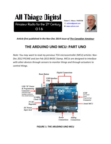
AN4488Power supplies2Power supplies2.1IntroductionThe device requires a 1.8 V to 3.6 V operating voltage supply (VDD), which can be reduceddown to 1.7V with some restrictions. See relative DataSheets for details. An embeddedregulator is used to supply the internal 1.2 V digital power.The real-time clock (RTC) and backup registers can be powered from the VBAT voltagewhen the main VDD supply is powered off.2.1.1Independent A/D converter supply and reference voltageTo improve conversion accuracy, the ADC has an independent power supply that can befiltered separately, and shielded from noise on the PCB. the ADC voltage supply input is available on a separate VDDA pin an isolated supply ground connection is provided on the VSSA pinIn all cases, the VSSA pin should be externally connected to same supply ground thanVSSOn 100-pin package and aboveTo ensure a better accuracy on low-voltage inputs, the user can connect a separate externalreference voltage ADC input on VREF . The voltage on VREF may range from 1.8 V toVDDA.When available (depending on package), VREF– must be externally tied to VSSA.On packages smaller than 100-pinThe VREF and VREF- pins are not available, they are internally connected to the ADCvoltage supply (VDDA) and ground (VSSA).2.1.2Battery backupTo retain the content of the Backup registers when VDD is turned off, the VBAT pin can beconnected to an optional standby voltage supplied by a battery or another source.The VBAT pin also powers the RTC unit, allowing the RTC to operate even when the maindigital supply (VDD) is turned off. The switch to the VBAT supply is controlled by the powerdown reset (PDR) circuitry embedded in the Reset block.If no external battery is used in the application, it is highly recommended to connect VBATexternally to VDD.DocID026304 Rev 17/4140
Power supplies2.1.3AN4488Voltage regulatorThe voltage regulator is always enabled after reset. It works in three different modesdepending on the application modes. in Run mode, the regulator supplies full power to the 1.2 V domain (core, memoriesand digital peripherals) in Stop mode, the regulator supplies low power to the 1.2 V domain, preserving thecontents of the registers and SRAM in Standby mode, the regulator is powered down. The contents of the registers andSRAM are lost except for those concerned with the Standby circuitry and the Backupdomain.Note:Depending on the selected package, there are specific pins that should be connected eitherto VSS or VDD to activate or deactivate the voltage regulator. Refer to section "Voltageregulator" in datasheet for details.2.2Power supply schemesThe circuit is powered by a stabilized power supply, VDD. Caution:– The VDD pins must be connected to VDD with external decoupling capacitors: onesingle Tantalum or Ceramic capacitor (min. 4.7 µF typ.10 µF) for the package one100 nF Ceramic capacitor for each VDD pin. The VBAT pin can be connected to the external battery (1.65 V VBAT 3.6 V). If noexternal battery is used, it is recommended to connect this pin to VDD with a 100 nFexternal ceramic decoupling capacitor. The VDDA pin must be connected to two external decoupling capacitors (100 nFCeramic 1 µF Tantalum or Ceramic). The VREF pin can be connected to the VDDA external power supply. If a separate,external reference voltage is applied on VREF , a 100 nF and a 1 µF capacitors mustbe connected on this pin. In all cases, VREF must be kept between 1.65 V and VDDA. Additional precautions can be taken to filter analog noise: –VDDA can be connected to VDD through a ferrite bead.–The VREF pin can be connected to VDDA through a resistor (typ. 47 Ω).For the voltage regulator configuration, there is specific BYPASS REG pin (notavailable on all packages) that should be connected either to VSS or VDD to activate ordeactivate the voltage regulator specific.– 8/41The VDD voltage range is 1.8 V to 3.6 V (down to 1.7V with some restrictions, seerelative DataSheets for details)Refer to Chapter 2.3.5 and section "Voltage regulator" of the related devicedatasheet for details.When the voltage regulator is enabled, VCAP1 and VCAP2 pins must be connected to2*2.2 µF LowESR 2Ω Ceramic capacitor (or 1*4.7 µF LowESR 1Ω Ceramiccapacitor if only VCAP1 pin is provided on some packages).DocID026304 Rev 1
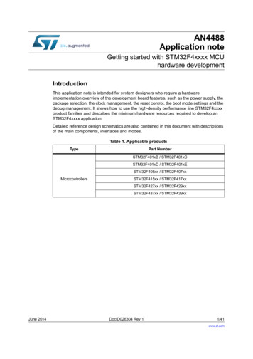
AN4488Power suppliesFigure 1. Power supply schemes d ĂĐŬƵƉ ĐŝƌĐƵŝƚƌLJ;K ϯϮ ͕Zd ͕tĂŬĞƵƉ ůŽŐŝĐ ĂĐŬƵƉ ƌĞŐŝƐƚĞƌƐ͕ďĂĐŬƵƉ Z DͿK hd' W /ͬK Ɛ/E;ŶŽƚĞ ϮͿs ϭͬϮͬ͘͘͘EE п ϭϬϬ Ŷ&н ϭ п ϰ͘ϳ ђ&/K ŽŐŝĐ ĞƌŶĞů ůŽŐŝĐ ; Wh͕ ĚŝŐŝƚĂů Θ Z DͿ s Wϭs WϮ;ϭ п ϰ͘ϳ ђ&ͿϮ п Ϯ͘Ϯ ђ&s ĞǀĞů ƐŚŝĨƚĞƌW Ž ǁĞƌ Ɛ ǁŝ ƚĐŚs d сϭ͘ϲϱ ƚŽ ϯ͘ϲssŽůƚĂŐĞƌĞŐ ƵůĂ ƚŽƌs ϭͬϮͬ͘͘͘E&ůĂƐŚ ŵĞŵŽƌLJ zW ͺZ 'W ZͺKEs s s Z &ϭϬϬ Ŷ&н ϭ ђ&ZĞƐĞƚ ĐŽŶƚƌŽůůĞƌϭϬϬ Ŷ&н ϭ ђ&;ŶŽƚĞ ϭͿ;ŶŽƚĞ ϯͿs Z &н;ŶŽƚĞ ϰͿs Z &Ͳ Ŷ Ă ůŽ Ő͗ Z Ɛ͕ W ͕͘͘͘s D ϯϯϴϴϬsϭ1. Optional. If a separate, external reference voltage is connected on VREF , the two capacitors (100 nF and1 µF) must be connected.2. VCAP2 is not available on all packages. In that case, a single 4.7 µF (ESR 1Ω) is connected to VCAP13. VREF is either connected to VREF or to VDDA (depending on package).4. VREF- is either connected to VREF- or to VSSA (depending on package).5. N is the number of VDD and VSS inputs.6. Refer to section "Voltage regulator" in datasheet (Table 1) to connect BYPASS REG and PDR ON pins.DocID026304 Rev 19/4140
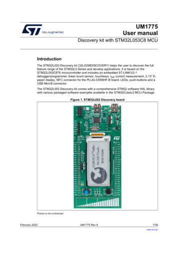
Power suppliesAN44882.3Reset & power supply supervisor2.3.1Power on reset (POR) / power down reset (PDR)The device has an integrated POR/PDR circuitry that allows proper operation starting from1.8 V.The device remains in the Reset mode as long as VDD is below a specified threshold,VPOR/PDR, without the need for an external reset circuit. For more details concerning thepower on/power down reset threshold, refer to the electrical characteristics in STM32F4xxxxdatasheets.The internal power-on reset (POR) / power-down reset (PDR) circuitry is disabled throughthe PDR ON pin. An external power supply supervisor should monitor VDD and shouldmaintain the device in reset mode as long as VDD is below a specified threshold. PDR ONshould be connected to this external power supply supervisor.Figure 2. Power-on reset/power-down reset waveform6 60/2 0 2RISING EDGE60/2 0 2FALLING EDGE0/2 M6HYSTERESIS0 24EMPORIZATIONT2344%-0/2%3%4AI B1. tRSTTEMPO is approximately 2.6 ms. VPOR/PDR rising edge is 1.74 V (typ.) and VPOR/PDR falling edge is1.70 V (typ.). Refer to STM32F4xxxx datasheets for actual value.2.3.2Programmable voltage detector (PVD)You can use the PVD to monitor the VDD power supply by comparing it to a thresholdselected by the PLS[2:0] bits in the Power control register (PWR CR).The PVD is enabled by setting the PVDE bit.A PVDO flag is available, in the Power control/status register (PWR CSR), to indicatewhether VDD is higher or lower than the PVD threshold. This event is internally connected toEXTI Line16 and can generate an interrupt if enabled through the EXTI registers. The PVDoutput interrupt can be generated when VDD drops below the PVD threshold and/or whenVDD rises above the PVD threshold depending on the EXTI Line16 rising/falling edgeconfiguration. As an example the service routine can perform emergency shutdown tasks.10/41DocID026304 Rev 1
AN4488Power suppliesFigure 3. PVD thresholds6 606 RISING EDGE606 FALLING EDGE M6HYSTERESIS06 THRESHOLD06 OUTPUTAI B2.3.3System resetA system reset sets all registers to their reset values except for the reset flags in the clockcontroller CSR register and the registers in the Backup domain (see Figure 1).A system reset is generated when one of the following events occurs:1.A low level on the NRST pin (external reset)2.window watchdog end-of-count condition (WWDG reset)3.Independent watchdog end-of-count condition (IWDG reset)4.A software reset (SW reset)5.Low-power management resetThe reset source can be identified by checking the reset flags in the Control/Status register,RCC CSR.The STM32F4xxxx does not require an external reset circuit to power-up correctly. Only apull-down capacitor is recommended to improve EMS performance by protecting the deviceagainst parasitic resets. See Figure 4.Charging and discharging a pull-down capacitor through an internal resistor increases thedevice power consumption. The capacitor recommended value (100 nF) can be reduced to10 nF to limit this power consumption;Figure 4. Reset circuit9''([WHUQDOUHVHW FLUFXLW15675 38)LOWHU6\VWHP UHVHW )3XOVHJHQHUDWRUPLQ V::'* UHVHW,:'* UHVHW3RZHU UHVHW6RIWZDUH UHVHW/RZ SRZHU PDQDJHPHQW UHVHWDL DocID026304 Rev 111/4140
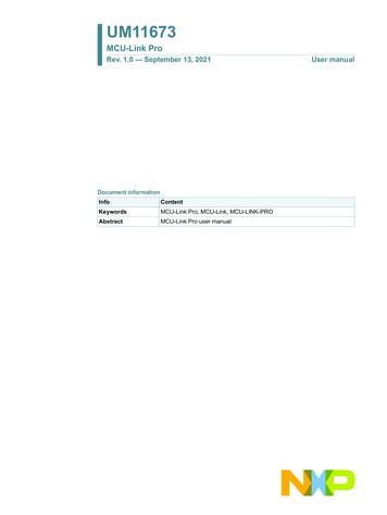
Power suppliesAN44882.3.4PDR ON circuitry exampleNote:Please contact STMicroelectronics in case you want to use different circuitry than describedhereafter.Restrictions: PDR ON 0 is mostly intended for VDD supply between 1.7 V and 1.9V (i.e. 1.8V /5% supply).Supply ranges which never go below 1.8V minimum should be better managed withinternal circuitry (no additional component thanks to fully embedded reset controller). To ensure safe power down, the external voltage supervisor (or equivalent) is requiredto drive PDR ON 1 during power off sequence.When the internal reset is OFF, the following integrated features are no longer supported: The integrated power-on reset (POR) / power-down reset (PDR) circuitry is disabled. The brownout reset (BOR) circuitry must be disabled. The embedded programmable voltage detector (PVD) is disabled. VBAT functionality is no more available and VBAT pin should be connected to VDD.Figure 5. PDR ON simple circuitry example9ROWDJH UHJXODWRU 9 W\S 9 PLQ9'' 9'' 9ROWDJH VXSHUYLVRU567DFWLYH KLJKRXWSXW3'5B219% 75HVHW FRQWUROOHUDFWLYH KLJK SXVK SXOO RXWSXW9''%66 RU HTXLYDOHQWRSWLRQDO LI 7VXSHUYLVRU 75677(032 Nȍ1567 )670 ) 966 966 06 9 12/41DocID026304 Rev 1
AN4488Power suppliesFigure 6. PDR ON simple circuitry timings example (Drawing not to scale)9''9'' GXULQJ RSHUDWLRQ NHSW DERYH 9VXSHUYLVRU KLJK WULS SRLQW 9VXSHUYLVRU ORZ WULS SRLQW3RZHU 2Q SKDVH2SHUDWLRQ3RZHU 'RZQ SKDVHWLPH3'5B2115679'' 93'5B21 PXVW JR DERYH 97VXSHUYLVRU5HVHW E\ LQWHUQDO VRXUFHV9, 75677(0327 ! 9,/WLPH1567 .HSW ORZ E\ LQWHUQDO 325 FLUFXLWU\1567 .HSW ORZ E\ H[WHUQDO 325 FLUFXLWU\1567 IRUFHG ORZ E\ H[WHUQDO DQG LQWHUQDO FLUFXLWU\06 9 Selection of PDR ON voltage supervisorVoltage supervisor should have the following characteristics Reset output active-high push-pull (output driving high when voltage is below trippoint) Supervisor trip point including tolerances and hysteresis should fit the expected VDDrange.Notice that supervisor spec usually specify trip point for falling supply, so hysteresisshould be added to check the power on phase.Example:–Voltage regulator 1.8V /- 5% mean VDD min1.71V–Supervisor specified at 1.66V /- 2.5% with an hysteresis of 0.5% mean- rising trip max 1.71V (1.66V 2.5% 0.5%)- falling trip min 1.62V (1.66V - 2.5%).DocID026304 Rev 113/4140
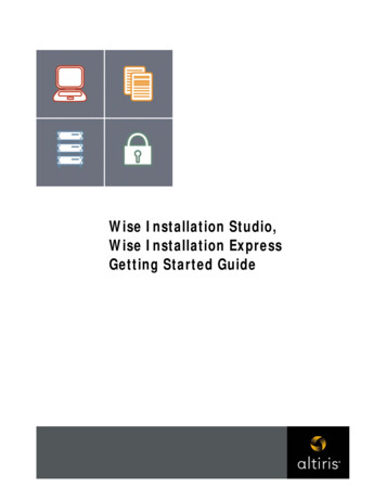
Power supplies2.3.5AN4488Regulator OFF modeRefer to section "Voltage regulator" in datasheet (Table 1) for details. When BYPASS REG VDD, the core power supply should be provided through VCAP1and VCAP1 pins connected together.–The two VCAP ceramic capacitors should be replaced by two 100 nF decoupling.–Since the internal voltage scaling is not managed internally, the external voltagevalue must be aligned with the targeted maximum frequency.–When the internal regulator is OFF, there is no more internal monitoring on V12.An external power supply supervisor should be used to monitor the V12 of thelogic power domain (VCAP).PA0 pin should be used for this purpose, and act as power-on reset on V12 powerdomain.In regulator OFF mode, the following features are no more supported:–PA0 cannot be used as a GPIO pin since it allows to reset a part of the V12 logicpower domain which is not reset by the NRST pin.–As long as PA0 is kept low, the debug mode cannot be used under power-onreset. As a consequence, PA0 and NRST pins must be managed separately if thedebug connection under reset or pre-reset is required.–The over-drive and under-drive modes are not available.–The Standby mode is not available.Figure 7. BYPASS REG supervisor reset connection9 ([WHUQDO 9& 3B SRZHU VXSSO\ VXSHUYLVRU([W UHVHW FRQWUROOHU DFWLYH SSOLFDWLRQ UHVHW ZKHQ 9& 3B 0LQ 9 VLJQDO RSWLRQDO3 1567% 3 66B5(*QRWH 9 [ Q) [ Q)9''9& 3 9& 3 9'' 11 î Q) î )966 1DL 9 1. VCAP2 is not available on all packages. In that case, a single 100 nF decoupling capacitor is connected toVCAP114/41DocID026304 Rev 1
AN4488Power suppliesThe following conditions must be respected:2.3.6 VDD should always be higher than VCAP to avoid current injection between powerdomains. If the time for VCAP to reach V12 minimum value is faster than the time for VDD to reach1.7 V, then PA0 should be kept low to cover both conditions: until VCAP reach V12minimum value and until VDD reaches 1.7 V. Otherwise, if the time for VCAP to reach V12 minimum value is slower than the time forVDD to reach 1.7 V, then PA0 could be asserted low externally. If VCAP go below V12 minimum value and VDD is higher than 1.7 V, then a reset mustbe asserted on PA0 pin.Regulator ON/OFF and internal reset ON/OFF availabilityTable 3. Regulator ON/OFF and internal power supply supervisor availabilityPackagepinsRegulator ONRegulator s(1)Yes(2)Power supplysupervisor ONPower supplysupervisor OFFYesNoYesPDR ON set to VDDYesPDR ON externalcontrol4864packages withpins on 4 edges100144100BGA Packages16917621649Chip ScalePackages901431. BYPASS REG set to VSS2. BYPASS REG set to VDDDocID026304 Rev 115/4140
PackageAN44883Package3.1Package SelectionPackage should be selected with various constrains strongly dependent of application.This list the much frequent user constrains (not in any order of preferences):–Amount of interfaces required.Some interfaces might not be available on some packages.Some interfaces combinations might not be possible on some packages–PCB technology constrains.Small pitch and high ball density might requires more PCB layers and higher classPCB–Package height–PCB available area–Noise emission or signal integrity of high speed interfaces.Smaller packages usually provide better signal integrity. This is further enhancedas Small pitch and high ball density requires multilayers PCB which allow bettersupply/ground distribution–Compatibility with other devices.Table 4. Package summary (Excluding WCSP)10 x 10 28 x 28 13 x 130.50.50.50.50.650.50.8Height (mm)0.61.61.60.61.61.60.60.61.61.1Sales numbers STM32F405x / 407x /415x / 417xLQFP1760.5LQFP1440.5LQFP1000.5LQFP64Pitch (mm)TFBGA2167x7LQFP20820 x 20 24 x 24UFBGA176 257x7UFBGA16910 x 10 14 x 14UFBGA1007x7UFQFPN48Size(mm)(1) STM32F42xx / 43xxSTM32F401B/C STM32F401D/E 1. body size, excluding pins16/41DocID026304 Rev 1
AN4488PackageTable 5. WCSP Package summarySales numbersNumber of ballsSize (mm)Pitch (mm)Height (mm)STM32F405x /407x /415x /417x904.258 x 4.0040.40.62STM32F42xx / 43xx1434.556 x 493.064 x 3.0640.40.585DocID026304 Rev 117/4140
Package3.2AN4488Pinout CompatibilityTable below allow to select the right package depending on required signals. Note the twodifferent pinouts for 64 and 100 pins which require specific connection in case boardcompatibility is required. See Table 8 and 9.Note that Chip Scale Package of different products even with same pinout might havedifferent package dimensions which might be taken into account for PCB clearance. SeeTable 5.Table 6. Pinout summaryxQFP/xQFNxBGAxCSPPin NameNumber of 168811301401683672114Specific IOs availabilityPA0-WKUP PB2-BOOT1 PC13-ANTI TAMP PC14-OSC32 IN PC15-OSC32 OUT PH0 - OSC IN PH1 - OSC OUT PI8- ANTI TAMP2System related pinsBOOT0 NRST BYPASS REG VDDA VREF PDR ONSupplies pins VBATVDDA/VREF VSSA VREF- VSSA/VREF(1)number of VDDnumber of VSS18/41 34612151741414183513323911144101119346DocID026304 Rev 1
AN4488PackageTable 6. Pinout summary(continued)xQFP/xQFNxBGAxCSPPin NameVCAP14864100144176208100 VCAP21691762164990143 1. One single Tantalum or Ceramic capacitor (min. 4.7 µF typ.10 µF) for the package one 100 nF Ceramic capacitor foreach VDD pin3.2.1Compatibility within STM32F4x familyFigure 8. STM32F4 family compatible board design for LQFP64 package1RW SRSXODWHG ZKHQ UHVLVWRU RU VROGHULQJ EULGJH SUHVHQW 966 966 UHVLVWRU RU VROGHULQJ EULGJH SUHVHQW IRU WKH 670 ) [ FRQILJXUDWLRQV QRW SUHVHQW LQ RWKHUV 670 ) [[ FRQILJXUDWLRQ 966 9661RW SRSXODWHG ZKHQ 966 UHVLVWRU RU VROGHULQJ EULGJH SUHVHQW 3RSXODWHG ZKHQ UHVLVWRU RU VROGHULQJ EULGJH SUHVHQW 06 9 Figure 9. STM32F4 family compatible board design for LQFP100 package UHVLVWRU RU VROGHULQJ EULGJH SUHVHQW IRU WKH 670 ) [ FRQILJXUDWLRQV QRW SUHVHQW LQ RWKHUV 670 ) [[ FRQILJXUDWLRQ 966 DocID026304 Rev 19661RW SRSXODWHG ZKHQ 966 UHVLVWRU RU VROGHULQJ EULGJH SUHVHQW 3RSXODWHG ZKHQ UHVLVWRU RU VROGHULQJ EULGJH SUHVHQW 06 9 19/4140
Package3.2.2AN4488Compatibility with STM32F1x and STM32F2x familiesFigure 10. Compatible board design STM32F10xx/STM32F4xx for LQFP64 package1RW SRSXODWHG ZKHQ UHVLVWRU RU VROGHULQJ EULGJH SUHVHQW 966 UHVLVWRU RU VROGHULQJ EULGJHSUHVHQW IRU WKH 670 ) [[ DQG 670 ) [ FRQILJXUDWLRQ QRW SUHVHQW LQ WKH 670 ) [[ FRQILJXUDWLRQ 966 966 9661RW SRSXODWHG ZKHQ 966 UHVLVWRU RU VROGHULQJ EULGJH SUHVHQW 3RSXODWHG ZKHQ UHVLVWRU RU VROGHULQJ EULGJH SUHVHQW DL EFigure 11. Compatible board design STM32F10xx/STM32F2xx/STM32F4xx forLQFP100 package966 UHVLVWRU RU VROGHULQJ EULGJH SUHVHQW IRU WKH 670 ) [[ DQG 670 ) [ FRQILJXUDWLRQV QRW SUHVHQW LQ RWKHUV 670 ) [[ FRQILJXUDWLRQ 966 966 9669'' 9667ZR UHVLVWRUV FRQQHFWHG WR
Reference documents AN4488 6/41 DocID026304 Rev 1 1 Reference documents The following documents are available on www.st.com Table 2. Referenced Documents Reference Title AN2867 Oscillator design guide for ST microcontrollers AN2606 STM32 microcontroller system memory boot mode AN3364 Migration and compatibility guidelines for STM32 microcontroller