Transcription
MCU-Link ProUM11673UM11673MCU-Link ProRev. 1.0 — September 13, 2021Document informationInfoContentKeywordsMCU-Link Pro, MCU-Link, MCU-LINK-PROAbstractMCU-Link Pro user manualUser manual
UM11673NXP SemiconductorsMCU-Link ProRevision historyRevDateDescription1.020210831First releaseContact informationFor more information, please visit: http://www.nxp.comFor sales office addresses, please send an email to: salesaddresses@nxp.comUM11673User manualAll information provided in this document is subject to legal disclaimers.Rev. 1.0 — 13 September 2021 NXP B.V. 2021. All rights reserved.2 of 15
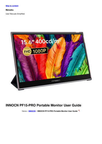
UM11673NXP SemiconductorsMCU-Link Pro1. IntroductionJointly developed by NXP and Embedded Artists, MCU-Link Pro is a powerful and costeffective debug probe that can be used seamlessly with MCUXpresso IDE, and is alsocompatible with 3rd party IDEs that support CMSIS-DAP protocol. MCU-Link Pro includesmany features to facilitate embedded software development, from basic debug toprofiling, energy consumption analysis, and support of peripheral and host emulation viaUSB bridging functions. MCU-Link Pro is one of a range of debug solutions based on theMCU-Link architecture, which includes a very low cost base model and implementationsbuilt into NXP evaluation boards. MCU-Link solutions are based on the powerful, lowpower LPC55S69 microcontroller and all versions run the same firmware from NXP. TheMCU-Link Pro can be programmed with a special version of firmware to implement aversion of SEGGER’s popular J-Link debug probe.Fig 1.MCU-Link ProThe MCU-Link Pro includes following features: CMSIS-DAP firmware to support all NXP Arm Cortex -M based MCUs with SWDdebug interfaces SEGGER J-Link firmware optionHigh speed USB host interfaceUSB to target UART bridge (VCOM)Simultaneous target supply and current measurementSWO profiling and I/O featuresUSB SPI and I2C bridges for programming/provisioning and host-based applicationdevelopment Option to power target system at up to 350mA (at 1.8V or 3.3V) Analog signal trace inputUM11673User manualAll information provided in this document is subject to legal disclaimers.Rev. 1.0 — 13 September 2021 NXP B.V. 2021. All rights reserved.3 of 15
UM11673NXP SemiconductorsMCU-Link Pro On-board, user-programmable LPC804 for peripheral emulation Multiple status LEDs for diagnosis of issues Target reset buttonUM11673User manualAll information provided in this document is subject to legal disclaimers.Rev. 1.0 — 13 September 2021 NXP B.V. 2021. All rights reserved.4 of 15
UM11673NXP SemiconductorsMCU-Link Pro2. Board layout and SettingsThe connectors and jumpers on the MCU-Link Pro are shown in Figure 1 and descriptionsof these are shown in Table 1.Table 1.Indicators, jumpers, buttons and connectorsCircuit ref DescriptionDefaultRefLED1-7Status LEDsn/a4.7J1Host USB connectorn/a2J2Multi-probe sync (reserved for future use)n/an/aJ3LPC55S69 SWD connector (for development of custom debug probecode only)n/a4.9J4Firmware update jumper (ISP)Open3.2J5Target voltage selection (when powering target)Open: 3.3VClosed: 1.8VOpen4.2J6Insert to power target from MCU-Link ProOpen4.2J7SWD connector for connection to target systemn/a4.1J9Energy measurement connectorn/a4.4J10VDDIO selection for LPC8043.3V (1-2)4.8J11SWD connector for LPC804n/a4.8J12Connector for LPC804 peripheralsn/a4.8J13SWD disable jumper (install to disable)Open4.1J14VCOM disable jumper (install to disable)Open4.3J15USBSIO (I2C/SPI USB bridge) disable jumper (install to disable)Open4.5J16/17/18Energy measurement range configurationHigh (350mA) range(pos 1-2)4.4J19MCU-Link digital connector (for VCOM, bridge and analog trace signals)n/a4J26UART connection to LPC55S69 (for development of custom debug probe n/acode only)4.9SW1Target reset button4.1n/a3. Installation and firmware optionsMCU-Link Pro debug probes are factory programmed with NXP’s CMSIS-DAP protocolbased firmware, which also supports all other features supported in hardware. A customversion of J-Link firmware to make MCU-Link Pro compatible with J-Link LITE is alsoavailable but note that this firmware is limited to supporting debug (including SWO) andVCOM features.3.1 Host driver and utility installationA step-by-step installation guide for MCU-Link Pro is provided at the board web page onnxp.com (https://www.nxp.com/demoboard/MCU-LINK-PRO.) The rest of this sectionexplains the same steps as can be found on that page.UM11673User manualAll information provided in this document is subject to legal disclaimers.Rev. 1.0 — 13 September 2021 NXP B.V. 2021. All rights reserved.5 of 15
UM11673NXP SemiconductorsMCU-Link ProMCU-Link debug probes are supported on Windows 10, MacOS X and Ubuntu Linuxplatforms. MCU-Link probes use standard OS drivers but the installation program forWindows includes information files to provide user friendly device names. To install theseinformation files and the firmware MCU-Link Pro update utility, go to the DesignResources section of the board web page click on and then select “Developmentsoftware” from the SOFTWARE section. Installation packages for each host OS will beshown.Download the package for your host OS install (Linux or MacOS) or run the installer(Windows). After setting up the OS drivers, your host computer will be ready to use withMCU-Link Pro, however it is advisable to update to the latest version of the firmware asthis may have changed since your MCU-Link Pro was manufactured; see Section 3.2 forthe steps to do this update.3.2 Updating MCU-Link Pro firmwareTo update the MCU-Link’s firmware it must be powered up in (USB) ISP mode. To do thisinsert jumper J4 then connect MCU-Link Pro to your host computer using a micro B USBcable connected to J1. The red STATUS LED (LED3) should light and stay on (for furtherinformation on LED status information refer to Section 4.7. The board will enumerate onthe host computer as a HID class device. Navigate to the MCU-LINK installer Vx xxxdirectory (where Vx xxx indicates the version number, e.g. V2.244), then follow theinstallation instructions in the readme.txt to find and run the firmware update utilities forCMSIS-DAP or J-Link versions. After updating the firmware using one of these scripts,unplug the board from the host computer, remove J4 and then reconnect the board.After programming the MCU-Link Pro with the CMSIS-DAP firmware three USB HIDdevices will enumerate, plus a virtual com port, as shown below (for Windows hosts):Fig 2.MCU-Link USB devicesThe red status LED will repeatedly fade from on to off and back on again (“breathing”),while the green USB status LED will stay on constantly. For more information on thestatus LEDs when using CMSIS-DAP firmware please see Section 4.7.If the J-Link firmware is programmed then only a J-Link device and single VCOM port willenumerate. Note that the J-Link firmware uses the VCOM LED to indicate status. TheLED will illuminate after boot up then blink to indicate debug activity.UM11673User manualAll information provided in this document is subject to legal disclaimers.Rev. 1.0 — 13 September 2021 NXP B.V. 2021. All rights reserved.6 of 15
UM11673NXP SemiconductorsMCU-Link ProIf a more recent firmware version is available for MCU-Link, MCUXpresso IDE (fromversion 11.3 onwards) will alert you to this when you use the probe in a debug session. Ifyou are using another IDE with the MCU-Link Pro it is advisable to update the firmware toensure the latest version of firmware is installed.Once the J-Link firmware has been installed, the SEGGER device drivers will be able toperform subsequent firmware updates as these are released without the need to use theNXP supplied firmware update scripts and without having to install the ISP mode jumper.Note that if the CMSIS-DAP firmware is installed later then this update capability will belost until the J-Link firmware is installed again using the NXP firmware update scripts.3.3 Setup for use with development toolsThe MCU-Link debug probe can be used with IDEs supported within the MCUXpressoecosystem (MCUXpresso IDE, IAR Embedded Workbench, Keil MDK); for moreinformation on getting started with these IDEs please visit the Getting Started section ofthe MCU-Link Pro page on nxp.com.3.3.1 Use with MCUXpresso IDEMCUXpresso IDE will recognize any type of MCU-Link probe, either with CMSIS-DAP orJ-Link firmware, and will show the probe types and unique identifiers of all probes it findsin the probe discovery dialog when starting a debug session. This dialog will also showthe firmware version, and will show a warning if the firmware is not the latest version. SeeSection 3.2 for information on how to update the firmware. MCUXpresso IDE 11.3 or latermust be used when using MCU-Link Pro, and version 11.4.1 or later is required to use theEnergy Measurement features.3.3.2 Use with other IDEsMCU-Link Pro should be recognized as a CMSIS-DAP or J-Link probe by other IDEs(depending on the firmware that is programmed), and should be usable with standardsettings for that probe type. Follow IDE vendor instructions for setup and use ofCMSIS-DAP and J-Link probe types.4. Feature descriptionsThis section describes the various features of MCU-Link Pro. The USB bridging, VCOMport, power measurement and analog trace features all utilize the Digital I/O Connector(J19), for which an accompanying cable is provided with the MCU-Link Pro. The tablebelow shows the connections for J19. All the signal pins on J19 have ESD protection. SPI,I2C and triggering digital signals used can be in the range 1.2V to 5.5V; if no target VDDIO reference is used then the circuit will default to 3.3V. Note the Analog trace inputshould be kept in the 0 to 3.3V range to avoid damage to the voltage follower circuitry onMCU-Link Pro.Table 2.UM11673User manualDigital I/O ConnectorCable colorJ19 pinSignalBlack1GNDAll information provided in this document is subject to legal disclaimers.Rev. 1.0 — 13 September 2021Feature NXP B.V. 2021. All rights reserved.7 of 15
UM11673NXP SemiconductorsMCU-Link ProTable 2.Digital I/O ConnectorCable colorJ19 pinSignalFeatureBrown2SPI SSELUSB-SPI bridgeRed3SPI MOSIOrange4SPI CLKYellow5SPI MISOGreen6I2C SDABlue7I2C SCLViolet8UART IN (Target TXD)USB-I2C bridgeVCOMGray9UART OUT (Target RXD)White10SYNC trigger (for future use)Black11GNDBrown12Analog trace inputAnalog traceRed13Energy Measurement triggerEnergy measurementOrange14Target VDD IO Reference voltage4.1 Target SWD/SWO interfaceMCU-Link Pro provides support for SWD-based target debug, including features enabledby SWO. The MCU-Link Pro board includes footprints for both 10 (J7) and 20 pin (J8)Cortex debug connectors, with the 10-pin connector installed. MCU-Link Pro comes withcables for 10-pin to 10-pin and 10-pin to 20-pin target connections.Level shifters are provided between the LPC55S69 MCU-Link Probe processor and thetarget to enable target processors running at between 1.2V and 5V to be debugged. Areference voltage tracking circuit is used to detect the target voltage at the SWDconnector and set the level shifter target-side voltage appropriately (see schematic page5.)The Target SWD interface can be disabled by installed jumper J13 but note that theMCU-Link software only checks this jumper at boot up time.SWO activity is indicated by the SWO status LED, which will illuminate/flicker when SWOdata is being sent/received on this interface (this can happen during profiling and duringenergy measurement.)A target reset button (SW1) is provided on MCU-Link Pro; note that this does not reset theLPC55S69 MCU-Link processor.4.2 Powering the targetMCU-Link Pro provides an option power to the target system (via the target SWDconnector) from one of its on-board regulators. The target supply voltage can be set to1.8V or 3.3V using jumper J5 (open for 3.3V, closed for 1.8V). The maximum supplycurrent from this regulator is 350mA. Note that the USB power capabilities of hostcomputer being used may affect the maximum current available. When using the targetpowering feature jumper J6 must also be installed in order to correctly set the referencevoltage level at the SWD connector. See the schematic page 5 for more information.UM11673User manualAll information provided in this document is subject to legal disclaimers.Rev. 1.0 — 13 September 2021 NXP B.V. 2021. All rights reserved.8 of 15
UM11673NXP SemiconductorsMCU-Link Pro4.3 VCOM (USB to Target UART bridge)MCU-Link Pro includes a UART to USB bridge (VCOM) function. A target system UARTcan be connected to the MCU-Link Pro via connector J19 (pin 8 and 9) using the suppliedcable. The Violet wire connects to the MCU-Link Pro UART input (target TXD) and Gray tothe UART output (target RXD). VCOM activity is indicated by the VCOM status LED,which will illuminate/flicker when traffic is present on this interface.The MCU-Link Pro VCOM device will enumerate on the host computer system with aname MCU-Link Vcom Port (COMxx) where “xx” will be a dependent on host system.Each MCU-Link board will have a unique VCOM number associated with it. The VCOMfunction may be disabled by installing jumper J14 before powering the board. Note thatinstalling/removing this jumper after powering the board will have no effect on the featurein terms of how the MCU-Link Pro software behaves since it is only checked at power up.It is not necessary to disable the VCOM function when not in use.The VCOM device is configurable via the host computer (e.g. Device Manager inWindows), with the follow parameters: Word length 7 or 8 bits Stop bits: 1 or 2 Parity: none / odd / evenBaud rates of up to 5.33Mbps are supported.4.4 Energy measurementMCU-Link includes circuitry to measure the Target’s supply voltage and current drawn,and the Energy Measurement features in MCUXpresso IDE can display this measurementdata along with energy and power consumption. For information on MCUXpresso IDEplease visit https://www.nxp.com/mcuxpresso and follow links to the IDE page.Current into the Target is measured at J9 by measuring the voltage drop across senseresistors on the MCU-Link Pro. J9 should be connected in line with the supply with pin 1as the supply side connection and pin 3 as the target side. J9 pin 2 should be groundedclose to these connections to provide good measurement integrity.MCU-Link Pro has two current measurement configurations available, with eachconfiguration having a maximum measurable current. This is to allow the maximumaccuracy of measurement for various different targets. Within each configuration there aretwo, automatically controlled ranges in order to provide and even further higher accuracyto be achieved. The automatic switching from low current measurement to high currentmeasurement is controlled solely by hardware in order to avoid excessive voltage dropacross the sense resistor. When switching from high current to low current measurementthe MCU-Link Pro firmware controls the switch back to low current measurementstriggered by an interrupt from a monitoring circuit.The measurement circuit self-calibrates each time the MCU-Link Pro is powered on. Nouser intervention is required to setup the calibration or adjust the measurement ranges.Transistors are used to isolate the sensing circuitry from the target supply to avoidcontention and ensure a known voltage is applied to the system during calibration, so it isUM11673User manualAll information provided in this document is subject to legal disclaimers.Rev. 1.0 — 13 September 2021 NXP B.V. 2021. All rights reserved.9 of 15
UM11673NXP SemiconductorsMCU-Link Pronot necessary to disconnect / reconnect the MCU-Link Pro. It is recommend to power theMCU-Link Pro first when not using the MCU-Link Pro to power the target as the MCU-Linkcould be back-powered through the current measurement circuit.The power measurement feature is intended for low power measurements, with a targetMCU running at up to 3.6V. The design uses the LPC55S69 16-bit ADC, with power datasampled at up to 100kS/s. At high sample rates MCUXpresso IDE may not be able tocapture all data, so the sample rate may need to be adjusted using the configurationoptions in the Energy Measurement configuration settings in that tool.4.4.1 Measurement range configurationAs mentioned above, MCU-Link Pro has two maximum current range measurementconfigurations, with the lower range providing better resolution at very low currents. If thetarget current exceeds the maximum current for the selected range then the measurementwill clip and hence be inaccurate, but the target operation may continue as normal(provided the current is not high enough to cause a significant drop across the highcurrent sense resistor and hence cause a brown out and/or trigger glitch securityprotection on some devices). Note that the MCU-Link Pro on-board regulator for the targetis limited to a maximum of 350mA output.Range configuration settings with corresponding accuracy and resolution are shownbelow. Note that all settings for J16/J17/J18 must be consistent for correct operation.Accuracy may vary with temperature and is provided for reference purposes only.Table 3.Energy measurement range configuration (as at firmware revision 2.243)Maximum measureablecurrentJ16J17J18Measurementsetting setting setting rangesResolution Accuracy(typical)50mA2-32-32-3200nA to 400uA 400uA to 50mA200nA5uA350mA1-21-21-210uA to 1.5mA1uA 1.5mA to 350mA 20uA1%1%1%5%4.5 SPI and I2C bridging (USB to Target SPI and/or I2C bridge, USBSIO)MCU-Link Pro includes a capability to bridge SPI and/or I2C ports to a host computer viaUSB, called USBSIO. This port bridging function can be used for emulating a system host,peripherals (in the case of I2C) and/or for device programming via the ISP feature. NXP’sMCUXpresso SEC tool has an option to program a target system via this bridge (see SECtool documentation for details). USBSIO activity is indicated by the USBSIO status LED,which will illuminate/flicker when traffic is present on this interface. This feature issupported by a free host library from NXP called LIBUSBSIO; for more details on thislibrary please visit https://www.nxp.com/libusbsio.The SPI interface connections are routed via level shifters/buffers with the target side IOvoltage determined by the voltage connected to the VDD IO REF signal at pin 14 of J19.The I2C interface connections are routed to an open drain buffer on the MCU-Link Pro.USBSIO may be disabled by inserting jumper J15 before powering the MCU-Link Pro; thiswill instruct the firmware not to enumerate the USB end point for USBSIO (which is called“MCU-Link LPCSIO” for backward compatibility reasons). Note that installing/removingthis jumper after powering the board will have no effect on the feature in terms of how theUM11673User manualAll information provided in this document is subject to legal disclaimers.Rev. 1.0 — 13 September 2021 NXP B.V. 2021. All rights reserved.10 of 15
UM11673NXP SemiconductorsMCU-Link ProMCU-Link software behaves since it is only checked at power up. While it is not necessaryto disable this feature it may have benefits in performance of SWO profiling and powermeasurement as the MCU-Link Pro shares USB bandwidth between these devices.4.6 Analog probeMCU-Link Pro includes an analog signal input that can be used with MCUXpresso IDE toprovide a basic signal tracing feature. As at version 11.4 of MCUXpresso IDE this featureis included with the energy measurement dialogs.The analog input for this feature is located at pin 12 of the (Digital) I/O connector J19, asdescribed at the start of this section. The input passes through a voltage follower/bufferand into an ADC input of the LPC55S69. Care should be taken not to apply voltages 3.3V to this input in order to avoid damage.4.7 Status LEDsMCU-Link Pro includes 7 LEDs to help diagnose issues and check that debug sessionsare working as expected. The table below shows the purpose/function of each of theseLEDs when using the CMSIS-DAP firmware. Note that the label for each LED can befound on the silkscreen on the back of the board.Table 4.MCU-Link Pro Firmware Status LEDs (CMSIS-DAP firmware)CircuitRefLabel: PurposeDescriptionColorLED1USB: USB enumerated Illuminated at start up after successful USBenumeration (remains lit).LED2SWO: SWO activityGreenDoes not light when in ISP mode.Indicates when SWO data is being received fromthe target.GreenDoes not light when in ISP mode.LED3Status: Status / activity Multi-function:RedNormal operation Blinks rapidly if error occurs at start up. Combination of heartbeat (slow fade in/out) whenrunning normally, with SWD activity overlaidISP mode (firmware update) On when LPC55S69 is booted in ISP modeLED4VCOM: VCOM activityIndicates when VCOM interface is active (datatransmission/reception).GreenLED5FUNCReserved for future useGreenLED6SIO: USBSIO activeIndicates when USBSIO bridge traffic is present.GreenLED7NRG: Energymeasurement activeIndicates when energy measurementcommunication is occurring between Target andMCU-Link.Does not light when in ISP mode.Does not light when in ISP modeGreenDoes not light when in ISP mode.UM11673User manualAll information provided in this document is subject to legal disclaimers.Rev. 1.0 — 13 September 2021 NXP B.V. 2021. All rights reserved.11 of 15
UM11673NXP SemiconductorsMCU-Link Pro4.8 LPC804 user-programmable processorAn LPC804 in a 20-pin package is included on MCU-Link Pro. This MCU can be used forany purpose but is intended for emulating peripherals or host computers to assist withprototyping.The LPC804 can be operated at 1.8V or 3.3V, selected using jumper J10 (position 1-2 for3.3V or 2-3 for 1.8V). The LPC804’s UART port that supports ISP (in system programmingboot) is connected to the LPC55S69 MCU-Link processor, and the LPC55S69 can alsocontrol the ISP and Reset of the LPC804. This hardware configuration will enable futuretools from NXP to boot load the LPC804. Code can also be downloaded and debugged onthe LPC804 using its SWD connector (J11).There are two LEDs on MCU-Link Pro associated with the LPC804 and their functions areshown in the table below.Table 5.LPC804 LEDsCircuitRefFunctionColorLED8ISP/User LED for LPC804. Connected to PIO0 12 of the LPC804, this LED Redcan be used by user applications running on this MCU. The LED willilluminate when the MCU-Link Pro asserts the ISP signal to the LPC804 inorder to boot it (this functionality reserved for future use).LED9User LED for LPC804, controlled by PIO0 13. Note that the factory default Greenprogram for the LPC804 is a simple blinky example (based on theMCUXpresso SDK for LPC804) that blinks this LED.The J12 expansion connector provides access to UART, I2C, SPI and 3 GPIOs ports ofthe LPC804. This MCU has a switch matrix that allows re-mapping of most of itsperipherals to most available pins, so the connections shown are suggested and not fixedfunction - refer to the LPC804 datasheet on nxp.com for more information.Note that no ESD protection or level shifting is provided for these signals so appropriateconnections should be made for the LPC804 supply voltage selected.Table 6.UM11673User manualLPC804 Connector for demo signals (J12)PinInterface signals1TXD (PIO0 1)2RXD (PIO 7)3SDA (PIO0 10)4SCL (PIO0 11)5SPI SSEL (PIO0 14)6SPI MOSI (PIO0 15)7SPI MISO (PIO0 16)8SPI SCK (PIO0 17)9GPIO (PIO0 8)10GPIO (PO0 9)11GPIO (same as Green user LED) (PIO0 13)12GNDAll information provided in this document is subject to legal disclaimers.Rev. 1.0 — 13 September 2021 NXP B.V. 2021. All rights reserved.12 of 15
UM11673NXP SemiconductorsMCU-Link Pro4.9 LPC55S69 debug and UART connectorsMost users of MCU-Link Pro are expected to use the standard firmware from NXP and sowill not need to debug the LPC55S69 MCU-Link processor, however SWD connector J3and may be used to develop code on this processor. One of the available UARTs(Flexcomm 1, using PIO1 10 and PIO1 11) is also routed to connector J26, which hasthe signal connections for an FTDI TTL-232R-3V3 cable (see schematic page 3 for moreinformation.)UM11673User manualAll information provided in this document is subject to legal disclaimers.Rev. 1.0 — 13 September 2021 NXP B.V. 2021. All rights reserved.13 of 15
UM11673NXP SemiconductorsMCU-Link Pro5. Legal information5.1DisclaimersLimited warranty and liability — Information in this document is believed to be accurate and reliable. However, NXPSemiconductors does not give any representations or warranties, expressed or implied, as to the accuracy or completeness ofsuch information and shall have no liability for the consequences of use of such information.In no event shall NXP Semiconductors be liable for any indirect, incidental, punitive, special or consequential damages (including- without limitation - lost profits, lost savings, business interruption, costs related to the removal or replacement of any productsor rework charges) whether or not such damages are based on tort (including negligence), warranty, breach of contract or anyother legal theory.Notwithstanding any damages that customer might incur for any reason whatsoever, NXP Semiconductors’ aggregate andcumulative liability towards customer for the products described herein shall be limited in accordance with the Terms andconditions of commercial sale of NXP Semiconductors.Right to make changes — NXP Semiconductors reserves the right to make changes to information published in this document,including without limitation specifications and product descriptions, at any time and without notice. This document supersedesand replaces all information supplied prior to the publication hereof.Suitability for use — NXP Semiconductors products are not designed, authorized or warranted to be suitable for use in lifesupport, life-critical or safety-critical systems or equipment, nor in applications where failure or malfunction of an NXPSemiconductors product can reasonably be expected to result in personal injury, death or severe property or environmentaldamage. NXP Semiconductors accepts no liability for inclusion and/or use of NXP Semiconductors products in such equipmentor applications and therefore such inclusion and/or use is at the customer’s own risk.Applications — Applications that are described herein for any of these products are for illustrative purposes only. NXPSemiconductors makes no representation or warranty that such applications will be suitable for the specified use without furthertesting or modification.Customers are responsible for the design and operation of their applications and products using NXP Semiconductors products,and NXP Semiconductors accepts no liability for any assistance with applications or customer product design. It is customer’ssole responsibility to determine whether the NXP Semiconductors product is suitable and fit for the customer’s applications andproducts planned, as well as for the planned application and use of customer’s third party customer(s). Customers shouldprovide appropriate design and operating safeguards to minimize the risks associated with their applications and products.NXP Semiconductors does not accept any liability related to any default, damage, costs or problem which is based on anyweakness or default in the customer’s applications or products, or the application or use by customer’s third party customer(s).Customer is responsible for doing all necessary testing for the customer’s applications and products using NXP Semiconductorsproducts in order to avoid a default of the applications and the products or of the application or use by customer’s third partycustomer(s). NXP does not accept any liability in this respect.Export control — This document as well as the item(s) described herein may be subject to export control regulations. Exportmight require a prior authorization from national authorities.5.2TrademarksNotice: All referenced brands, product names, service names and trademarks are the property of their respective owners.UM11673User manualAll information provided in this document is subject to legal disclaimers.Rev. 1.0 — 13 September 2021 NXP B.V. 2021. All rights reserved.14 of 15
UM11673NXP SemiconductorsMCU-Link Pro6. 54.64.74.84.955.15.26UM11673User manualIntroduction . . . . . . . . . . . . . . . . . . . . . . . . . . . . 3Board layout and Settings . . . . . . . . . . . . . . . . 5Installation and firmware options. . . . . . . . . . . 5Host driver and utility installation . . . . . . . . . . . 5Updating MCU-Link Pro firmware . . . . . . . . . . . 6Setup for use with development tools. . . . . . . . 7Use with MCUXpresso IDE. . . . . . . . . . . . . . . . 7Use with other IDEs . . . . . . . . . . . . . . . . . . . . . 7Feature descriptions . . . . . . . . . . . . . . . . . . . . . 7Target SWD/SWO interface . . . . . . . . . . . . . . . 8Powering the target . . . . . . . . . . . . . . . . . . . . . 8VCOM (USB to Target UART bridge) . . . . . . . . 9Energy measurement . . . . . . . . . . . . . . . . . . . . 9Measurement range configuration . . . . . . . . . 10SPI and I2C bridging (USB to Target SPI and/or I2C bridge, USBSIO) 10Analog probe . . . . . . . . . . . . . . . . . . . . . . . . . 11Status LEDs . . . . . . . . . . . . . . . . . . . . . . . . . . 11LPC804 user-programmable processor . . . . . 12LPC55S69 debug and UART connectors . . . . 13Legal information. . . . . . . . . . . . . . . . . . . . . . . 14Disclaimers . . . . . . . . . . . . . . . . . . . . . . . . . . . 14Trademarks. . . . . . . . . . . . . . . . . . . . . . . . . . . 14Contents . . . . . . . . . . . . . . . . . . . . . . . . . . . . . . 15All information provided in this document is subject to legal disclaimers.Rev. 1.0 — 13 September 2021 NXP B.V. 2021. All rights reserved.15 of 15
User manual Rev. 1.0 — 13 September 2021 3 of 15 NXP Semiconductors UM11673 MCU-Link Pro 1. Introduction . (reserved for future use) n/a n/a J3 LPC55S69 SWD connector (for development of custom debug probe code only) . (pos 1-2) 4.4 J19 MCU-Link digital connector (for VCOM, bridge and analog trace signals) n/a 4 .
