Transcription
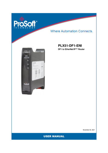
PLX51-DF1-ENIDF1 to EtherNet/IP RouterNovember 30, 2021USER MANUAL
Your Feedback PleaseWe always want you to feel that you made the right decision to use our products. If you havesuggestions, comments, compliments or complaints about our products, documentation, or support,please write or call us.ProSoft Technology, Inc. 1 (661) 716-5100 1 (661) 716-5101 hnology.comPLX51-DF1-ENI User ManualNovember 30, 2021ProSoft Technology , is a registered copyright of ProSoft Technology, Inc. All other brand or productnames are or may be trademarks of, and are used to identify products and services of, their respectiveowners.In an effort to conserve paper, ProSoft Technology no longer includes printed manuals with our productshipments. User Manuals, Datasheets, Sample Ladder Files, and Configuration Files are provided at ourwebsite: www.prosoft-technology.comContent DisclaimerThis documentation is not intended as a substitute for and is not to be used for determining suitability orreliability of these products for specific user applications. It is the duty of any such user or integrator toperform the appropriate and complete risk analysis, evaluation and testing of the products with respectto the relevant specific application or use thereof. Neither ProSoft Technology nor any of its affiliates orsubsidiaries shall be responsible or liable for misuse of the information contained herein. Information inthis document including illustrations, specifications and dimensions may contain technical inaccuraciesor typographical errors. ProSoft Technology makes no warranty or representation as to its accuracy andassumes no liability for and reserves the right to correct such inaccuracies or errors at any time withoutnotice. If you have any suggestions for improvements or amendments or have found errors in thispublication, please notify us.No part of this document may be reproduced in any form or by any means, electronic or mechanical,including photocopying, without express written permission of ProSoft Technology. All pertinent state,regional, and local safety regulations must be observed when installing and using this product. Forreasons of safety and to help ensure compliance with documented system data, only the manufacturershould perform repairs to components. When devices are used for applications with technical safetyrequirements, the relevant instructions must be followed. Failure to use ProSoft Technology software orapproved software with our hardware products may result in injury, harm, or improper operating results.Failure to observe this information can result in injury or equipment damage. 2021 ProSoft Technology. All Rights Reserved.For professional users in the European UnionIf you wish to discard electrical and electronic equipment (EEE), please contact yourdealer or supplier for further information.Warning – Cancer and Reproductive Harm – www.P65Warnings.ca.govAgency Approvals and CertificationsPlease visit our website: www.prosoft-technology.comProSoft Technology, Inc.Page 2 of 80
PLX51-DF1-ENIDF1 to EtherNet/IP RouterContentsUser ManualContentsYour Feedback Please . 2Content Disclaimer . 2Agency Approvals and Certifications . 21Preface1.11.21.31.41.525About the PLX35-NB2 Network Bridge . 5Features . 6Architecture . 7Additional Information . 10Support . 10Installation2.12.22.32.43Module Layout . 11Module Mounting . 13Power . 14RS232/RS485 Port . 7.13.7.2415Install Configuration Software . 15Network Parameters . 16Creating a New Project . 20DF1 Parameters. 22Message Routing . 26Bridge Mode. 26DF1 Slave Mode . 34Scheduled Tag Mode . 39Unscheduled Mode . 42Module Download . 43RSLogix 5000 Configuration . 46Studio 5000 Configuration (Version 20 ) . 46RSLogix 5000 Configuration (Pre-Version 20) . 50Operation4.14.24.2.14.2.24.151155Message Routing . 55RSLogix 5000 assemblies . 55Input Assembly . 56Output Assembly . 57Unscheduled Messaging . 58Diagnostics5.15.25.35.45.5ProSoft Technology, Inc.62LEDs . 62Module Status Monitoring . 63DF1 Packet Capture . 68Module Event Log . 71Web Server . 72Page 3 of 80
PLX51-DF1-ENIDF1 to EtherNet/IP Router6PrefaceUser ManualTechnical Specifications6.16.26.36.46.57Dimensions . 73Electrical . 74Ethernet . 74DF1 Protocol . 75Agency Approvals & Certifications. 75Appendix7.187376Example - Logix CPU to DF1 Bridge Mode . 76Support, Service & Warranty8.18.2ProSoft Technology, Inc.80Contacting Technical Support. 80Warranty Information . 80Page 4 of 80
PLX51-DF1-ENIDF1 to EtherNet/IP RouterPrefaceUser Manual1Preface1.1About the PLX35-NB2 Network BridgeThis manual describes the installation, operation, and diagnostics of the PLX51-DF1ENI. The PLX51-DF1-ENI provides intelligent data routing between EtherNet/IPTMand DF1 which can help simplify the migration from PLC2, PLC3, PLC5, and SLCsystems to ControlLogix or CompactLogixTM platforms, where a DF1 interface isrequired.The module can also be used for remote programming, bridging between Ethernetand DF1.Figure 1.1 - Migration PathProSoft Technology, Inc.Page 5 of 80
PLX51-DF1-ENIDF1 to EtherNet/IP Router1.2PrefaceUser ManualFeaturesThe PLX51-DF1-ENI is able to transfer data from a DF1 device to a maximum ofeight Logix controllers. The module operates in one of four modes, simplifying theconfiguration for all The PLX51-DF1-ENI redirects DF1 PCCC messages to a Logixcontroller at a preconfigured EtherNet/IP path.Logix PLC Mapping configuration may also be required.This mode also supports remote programming using RSLogix 5/ 500.The PLX51-DF1-ENI will convert DF1 PCCC messages toLogix controller tag reads or tag writes.No Logix PLC Mapping configuration is required.Remote DeviceThe PLX51-DF1-ENI transfers data between a DF1 device anda number of Logix tags, using a preconfigured schedule.PLX51-DF1-ENIDF1 SlaveScheduled TagRemote DeviceNo Logix or remote device configuration is required.UnscheduledThe PLX51-DF1-ENI transfers messages received from a LogixMessage Instruction.Logix (Msg)Table 1.1 – Modes of OperationThe PLX51-DF1-ENI is configured using the ProSoft PLX50 Configuration Utility.This program can be downloaded from www.prosoft-technology.com free of charge.The PLX50 Configuration Utility offers various configuration methods, including acontroller tag browser.Hereafter the PLX51-DF1-ENI will be referred to as the module.The module can operate in both a Logix “owned” and standalone mode. With a Logixconnection, the input and output assemblies will provide additional diagnosticsinformation which will be available in the Logix controller environment.The module uses isolated RS232 for DF1 communication providing better noiseimmunity. The RS232 port also uses a terminal block for convenient installation. Themodule can also be used in systems with redundant DF1 pathways.A built-in webserver provides detailed diagnostics of system configuration andoperation, including the display of received DF1 communication packets, without theneed for any additional software.ProSoft Technology, Inc.Page 6 of 80
PLX51-DF1-ENIDF1 to EtherNet/IP Router1.3PrefaceUser ManualArchitectureThe figure below provides an example of the typical network.Figure 1.2 - Example of a typical network setupBy converting and redirecting serial DF1 messages from legacy devices toEtherNet/IP, the module provides an interface for data exchange to ControlLogix andCompactLogix platforms.When connected to devices that provide more than one DF1 port, it is possible toimplement DF1 communication redundancy with the use of two PLX51-DF1-ENI’s.These can be configured in one of two modes, either Simultaneous or Active /Standby.In the Simultaneous mode, both modules route the same traffic to the same Logixcontroller. Effectively, the Logix controller will receive two of each message andprocess both of them.Active / Standby mode requires both modes to be Logix “Owned”. One of themodules has its routing capability disabled, achieved by setting the Inhibit Routing bitin the output assembly. Logic in the Logix controller can monitor the connection andperformance of the Active module and, if necessary, inhibit the Active module andun-inhibit the Standby module.ProSoft Technology, Inc.Page 7 of 80
PLX51-DF1-ENIDF1 to EtherNet/IP RouterPrefaceUser ManualFigure 1.3 - Redundant ArchitectureThe PLX51-DF1-ENI can be used in redundant Logix controller systems.Systems that rely on a central ControlLogix communicating to a number of remoteDF1 devices, e.g. MicroLogix and SLC stations, may find the PLX51-DF1-ENI usefulwhen upgrading to newer ControlLogix processors, which no longer have a serialport. These systems can easily be upgraded using the PLX51-DF1-ENI withoutaffecting the existing and often costly wireless infrastructure.ProSoft Technology, Inc.Page 8 of 80
PLX51-DF1-ENIDF1 to EtherNet/IP RouterPrefaceUser ManualFigure 1.4 – Remote MicroLogix SystemFigure 1.5 – Remote Programming (Half-duplex)ProSoft Technology, Inc.Page 9 of 80
PLX51-DF1-ENIDF1 to EtherNet/IP Router1.4PrefaceUser ManualAdditional InformationThe following documents contain additional information that can assist you with themodule installation and operation.ResourceLinkPLX50 Configuration Utility Softwarewww.prosoft-technology.comPLX51-DF1-ENI User ManualPLX51-DF1-ENI DatasheetExample Code & UDTswww.prosoft-technology.comEthernet wiring e/cde205 220 420/installation/guide/cde205 220 420 hig/Connectors.htmlCIP RoutingThe CIP Networks Library, Volume 1, Appendix C:DataManagementMap PLC/SLC messagesSLC to CompactLogix Migration Guide: Chapter 3 – MapPLC/SLC Messages (1769-ap001 -en-p.pdf)EtherNet/IP Network Configuration: Chapter 5 – Mapping Tags(enet-um001 -en-p.pdf)Table 1.2 - Additional InformationFor professional users in the European UnionIf you wish to discard electrical and electronic equipment (EEE), please contact yourdealer or supplier for further information.1.5SupportTechnical support is provided via the Web (in the form of user manuals, FAQ,datasheets etc.) to assist with installation, operation, and diagnostics.For additional support you can use either of the following:ResourceLinkContact Us linkwww.prosoft-technology.comSupport emailsupport@prosoft-technology.comTable 1.3 – Support DetailsProSoft Technology, Inc.Page 10 of 80
PLX51-DF1-ENIDF1 to EtherNet/IP Router2Installation2.1Module LayoutInstallationUser ManualThe module has three ports at the bottom of the enclosure. The ports are used forEthernet, RS232 serial, and power.The power port uses a three-way connector which is used for the DC power supply;positive and negative (or ground) voltage, as well as the earth connection.The RS232 port uses a four-way connector. This provides connection for thecommunication transmit (TX), receive (RX), and ground (GND) conductors. Thefourth connection is used for shielding the cable in high-noise environments.The Ethernet cable must be wired according to industry standards, which can befound in the additional information section of this document.Figure 2.1 - PLX51-DF1-ENI side and bottom viewThe module provides three diagnostic LEDs. These LEDs are used to provideinformation regarding the module system operation, the Ethernet interface, and theauxiliary communication interface (RS232).ProSoft Technology, Inc.Page 11 of 80
PLX51-DF1-ENIDF1 to EtherNet/IP RouterInstallationUser ManualFigure 2.2 – PLX51-DF1-ENI front and top viewThe module provides four DIP switches at the top of the enclosure as shown in thetop view figure above.DIP SwitchDescriptionDIP Switch 1Used to force the module into “Safe Mode”. When in “Safe Mode”, the module willnot load the application firmware and will wait for new firmware to be downloaded.This should only be used in the rare occasion when a firmware update wasinterrupted at a critical stage.DIP Switch 2This will force the module into DHCP mode which is useful when you haveforgotten the IP address of the module.DIP Switch 3ReservedDIP Switch 4Upon bootup, the Ethernet IP address will be set to 192.168.1.100 and networkmask 255.255.255.0. The DIP switch can then be set to ‘Off’ to allow theassignment of a static IP address, if needed.Table 2.1 - DIP Switch SettingsProSoft Technology, Inc.Page 12 of 80
PLX51-DF1-ENIDF1 to EtherNet/IP Router2.2InstallationUser ManualModule MountingThe module provides a DIN rail clip to mount onto a 35mm DIN rail.Figure 2.3 - DIN rail specificationThe DIN rail clip is mounted on the bottom of the module, toward the back. Use a flatscrew driver to pull the clip downward. This will enable you to mount the module ontothe DIN rail. Once the module is mounted onto the DIN rail, the clip must be pushedupward to lock the module onto the DIN rail.Figure 2.4 - DIN rail moutingProSoft Technology, Inc.Page 13 of 80
PLX51-DF1-ENIDF1 to EtherNet/IP Router2.3InstallationUser ManualPowerA three-way power connector is used to connect Power , Power– (GND), and earth.The module requires an input voltage of 10 to 28 VDC. Refer to the technicalspecifications section in this document.Figure 2.5 - Power connector2.4RS232/RS485 PortThe four-way RS232 connector is used to connect the transmit (TX), receive (RX),and GND conductors for serial communication. The shield terminal can be used forshielded cable in high noise environments.NOTE: The shield of the RS232 port is internally connected to thepower connector earth. Thus, when using a shield it is important toconnect the Earth terminal on the power connector to a clean earth.Failing to do this can lower the signal quality of the RS232communication.NOTE: When using a shielded cable, it is important that only one endof the shield is connected to earth to avoid current loops. It isrecommended to connect the shield to the PLX51-DF1-ENI module,not to the other DF1 device.Figure 2.6 - RS232 connectorProSoft Technology, Inc.Page 14 of 80
PLX51-DF1-ENIDF1 to EtherNet/IP RouterSetupUser Manual3Setup3.1Install Configuration SoftwareThe network setup and configuration of the PLX51-DF1-ENI is done in the ProSoftPLX50 Configuration Utility. This software can be downloaded from www.prosofttechnology.com.Figure 3.1 - ProSoft PLX50 Configuration Utility EnvironmentProSoft Technology, Inc.Page 15 of 80
PLX51-DF1-ENIDF1 to EtherNet/IP Router3.2SetupUser ManualNetwork ParametersThe module has DHCP (Dynamic Host Configuration Protocol) enabled as factorydefault. Thus, a DHCP server must be used to provide the module with the requirednetwork parameters (IP address, subnet mask, etc.). There are a number of DHCPutilities available, however it is recommended that the DHCP server in the PLX50Configuration Utility be used.Within the PLX50 Configuration Utility environment, the DHCP server can be foundunder the Tools menu.Figure 3.2 - Selecting DHCP ServerOnce opened, the DHCP server will listen on all available network adapters forDHCP requests and display their corresponding MAC addresses.Figure 3.3 - DHCP ServerNOTE: If the DHCP requests are not displayed in the DHCP Server, itmay be due to the local PC’s firewall. During installation, thenecessary firewall rules are automatically created for the Windowsfirewall. Another possibility can be another DHCP Server isoperational on the network and it has assigned the IP address.ProSoft Technology, Inc.Page 16 of 80
PLX51-DF1-ENIDF1 to EtherNet/IP RouterSetupUser ManualTo assign an IP address, click on the corresponding “Assign” button. The IP AddressAssignment window opens.Figure 3.4 - Assigning IP AddressThe required IP address can then be either entered, or a recently used IP addresscan be selected by clicking on an item in the Recent List.If the “Enable Static” checkbox is checked, then the IP address will be set to staticafter the IP assignment, thereby disabling future DHCP requests.Once the IP address window has been accepted, the DHCP server will automaticallyassign the IP address to the module and then read the Identity object Product namefrom the device.The successful assignment of the IP address by the device is indicated by the greenbackground of the associated row.Figure 3.5 - Successful IP address assignmentIt is possible to force the module back into DHCP mode by powering up the devicewith DIP switch 2 set to the On position.A new IP address can then be assigned by repeating the previous steps.ProSoft Technology, Inc.Page 17 of 80
PLX51-DF1-ENIDF1 to EtherNet/IP RouterSetupUser ManualNOTE: It is important to return DIP switch 2 back to the Off position,to avoid the module returning to a DHCP mode after the power iscycled again.In addition to the setting the IP address, a number of other network parameters canbe set during the DHCP process. These settings can be viewed and edited in thePLX50 Configuration Utility Application Settings, in the DHCP Server tab.Once the DHCP process has been completed, the network settings can be set usingthe Ethernet Port Configuration via the Target Browser.The Target Browser can be accessed under the Tools menu.Figure 3.6 - Selecting the Target BrowserThe Target Browser automatically scans the Ethernet network for EtherNet/IPdevices.Figure 3.7 - Target BrowserProSoft Technology, Inc.Page 18 of 80
PLX51-DF1-ENIDF1 to EtherNet/IP RouterSetupUser ManualRight-clicking on a device, reveals the context menu, including the Port Configurationoption.Figure 3.8 - Selecting Port ConfigurationThe Ethernet port configuration parameters can be modified using the PortConfiguration window.Figure 3.9 - Port ConfigurationAlternatively, these parameters can be modified using RSLinx.ProSoft Technology, Inc.Page 19 of 80
PLX51-DF1-ENIDF1 to EtherNet/IP Router3.3SetupUser ManualCreating a New ProjectBefore you configure the module, a new PLX50 Configuration Utility project must becreated. Under the File menu, select New.Figure 3.10 - Creating a new projectA PLX50 Configuration Utility project will be created, showing the Project Explorertree view. To save the project use the Save option under the File menu.Selecting Add under the Device menu.Figure 3.11 - Adding a new deviceProSoft Technology, Inc.Page 20 of 80
PLX51-DF1-ENIDF1 to EtherNet/IP RouterSetupUser ManualIn the Add New Device window, select the PLX51-DF1-ENI, and click the Ok button.Figure 3.12 – Selecting a new PLX51-DF1-ENIThe device appears in the Project Explorer tree as shown below, and itsconfiguration window opened.The device configuration window can be reopened by either double clicking themodule in the Project Explorer tree or right-clicking the module and selectingConfiguration.Figure 3.13 – PLX51-DF1-ENI configurationProSoft Technology, Inc.Page 21 of 80
PLX51-DF1-ENIDF1 to EtherNet/IP Router3.4SetupUser ManualDF1 ParametersThe DF1 parameters are configured by the PLX50 Configuration Utility. Refer to theadditional information section for documentation and installation links for the ProSoftPLX50 Configuration Utility. The DF1 parameter configuration consists of a generalconfiguration as well as a serial configuration. When downloading the configurationinto the module, it will be saved in non-volatile memory that persists when themodule is powered down.The General configuration tab consists of the following parameters:ParameterDescriptionInstance NameThis parameter is a user defined name to identify between various PLX51-DF1-ENI’s.DescriptionThis parameter is used to provide a more detailed description of the application for thePLX51-DF1-ENI.IP AddressIP address of the PLX51-DF1-ENI.Major RevisionThe major revision of the PLX51-DF1-ENI.ENIP Retry LimitThe amount of EtherNet/IP retries the module will make once no response was receivedfrom the Logix Controller.ENIP TimeOutThe time in milliseconds after which a retry is sent. Once the first retry is sent, the nextretry will be sent after the same amount of time. This will repeat until the ENIP Retry Limitis reached.Operating ModeThe Operating Mode determines how the DF1 messages are routed:In DF1 Slave mode, the module automatically routes the DF1 message and function tothe correct Logix tag. In this mode, the PLX51-DF1-ENI maps the DF1 request to thepreconfigured tag. Communication in this mode is initiated by the remote DF1 device.In Scheduled mode, the PLX51-DF1-ENI will initiate the exchange between the remoteDF1 device and Logix. Either by reading data from a DF1 device and writing it into apreconfigured Logix tag or vice versa. Communication in this mode is initiated by thePLX51-DF1-ENI.In Unscheduled mode, the PLX51-DF1-ENI routes Logix messages to the remote DF1device and returns the result. There is little configuration required in the PLX51-DF1-ENIas the routing information is configured by Logix for each message transaction.Communication in this mode is initiated by Logix.In Bridge mode, the module uses the PCCC message exchange to read or write varioustags in the Logix controller. Therefore, in this mode, the module relies on the Logixcontroller to map the DF1 request to the preconfigured Logix tag.Communication in this mode is initiated by the remote DF1 device.Refer to the message routing section for an explanation of the routing operation.Table 3.1 - General configuration parametersProSoft Technology, Inc.Page 22 of 80
PLX51-DF1-ENIDF1 to EtherNet/IP RouterSetupUser ManualThe DF1 General configuration window is opened by either double clicking on themodule in the tree or right-clicking the module and selecting Configuration.Figure 3.14 - General ConfigurationProSoft Technology, Inc.Page 23 of 80
PLX51-DF1-ENIDF1 to EtherNet/IP RouterSetupUser ManualThe Serial - DF1 configuration tab is shown in the figure below. The DF1 Serialconfiguration window is opened by either double clicking on the module in the tree orright-clicking the module and selecting Configuration.Figure 3.15 - Serial DF1 configurationThe Serial – DF1 configuration tab consists of the following parameters:ParameterDescriptionProtocolThe protocol parameter configures the module to operate in full duplex, halfduplex, or Radio Modem mode on the DF1 network.BAUD RateThe BAUD rate configures at what speed the data is sent across the RS232serial network. The module provides the following speeds:1200, 2400, 4800, 9600, 19200, 38400, 57600, and 115200ParityThis parameter configures the parity of the module’s RS232 serial port. Themodule allows for Even, Odd, or None parity setting.Error DetectionThe module can be configured to perform either BCC or CRC checksumvalidation on incoming and outgoing packets. CRC checksums is a muchstronger validation method when compared to BCC but is more processorintensive to perform.Embedded ResponsesThis parameter configures the module to add the acknowledge responses inthe data payload. You can configure the module to be Auto Detect or On.This function is only available in Full Duplex mode.Bridge Half-Duplex ModeThis parameter configures the port as a DF1 Slave or DF1 Master.Retry LimitThis determines how many times the module must retry and messageexchange before failing it.ProSoft Technology, Inc.Page 24 of 80
PLX51-DF1-ENIDF1 to EtherNet/IP RouterSetupUser ManualACK TimeoutThis is used to determine the interval between retries when a messageexchange has failed.Reply Msg WaitThis is the minimum delay before the DF1 reply is transmitted to the DF1device.Node AddressThis is only configurable in Unscheduled mode. In all other modes the nodeaddress is dynamically changed to suite the required mapping.EnableDuplicate DetectionThis configures the module to check for duplicate packets and flaggingthem when they occur.Enable Store andForwardWhen using the Radio Modem protocol, the PLX51-DF1-ENI can be used torepeat messages from other nodes on the radio network (only relevant forDF1 Radio Modem protocol).Repeat DelayWhen repeating packets from other nodes on the Radio network, thissetting determines the delay before repeating the packet (only relevant forDF1 Radio Modem protocol).Nodes to RepeatWhen Store and Forward has been enabled, the Nodes to Repeat list is allthe nodes numbers of the devices from which the PLX51-DF1-ENI mustrepeat the messages (only relevant for DF1 Radio Modem protocol).Table 3.2 - Serial DF1 configuration parametersProSoft Technology, Inc.Page 25 of 80
PLX51-DF1-ENIDF1 to EtherNet/IP Router3.5SetupUser ManualMessage RoutingThe module can be configured to route DF1 data in one of four modes: Bridge mode DF1 Slave mode Schedule Tag mode Unscheduled mode3.5.1 Bridge ModeThe Bridge Mode can be used for redirecting messages between the DF1 andEthernet port. This mode allows for various remote programming options and well asmapping DF1 (PCCC) messages to a Logix controller when using the Logix PLCmapping feature.To open the Bridge map configuration window by double clicking on the module inthe tree or right-clicking the module and selecting Configuration. Once in theconfiguration window select the third tab at the top Bridge. The Bridge mapconfiguration is shown in the figure below.Figure 3.16 - Bridge map configurationProSoft Technology, Inc.Page 26 of 80
PLX51-DF1-ENIDF1 to EtherNet/IP RouterSetupUser ManualThe module can emulate more than one destination DF1 Node Address, and thusroute multiple messages to different Ethernet devices. For this reason it is importantto enter the correct associate DF1 Node address in each mapping record.When using PCCC data messaging the connection class can be configured byselecting either Class 3 or Unconnected (UCMM) messaging. This is done byselecting from the Connection drop-down box in the Bridge tab.The controller paths can either be entered manually or you can browse to them byclicking the Browse button. The Target Browser requires the
The PLX51-DF1-ENI is configured using the ProSoft PLX50 Configuration Utility. This program can be downloaded from www.prosoft-technology.com free of charge. The PLX50 Configuration Utility offers various configuration methods, including a controller tag browser. Hereafter the PLX51-DF1-ENI will be referred to as the module.
