Transcription
SDR-IQ Interface SpecificationVer. 1.04Dec 18, 2013MoeTronixwww.moetronix.com
Table of Contents1. Purpose. 42. Basic Protocol Concepts. 43. Message Block Format. 63.1. Detailed Description of the Message Block Types and Their Purpose.83.1.1 Set Control Item. 83.1.2 Request Control Item. 83.1.3 Request Control Item Range. 83.1.4 Response to Set or Request Current Control Item. 83.1.5 Unsolicited Control Item. 83.1.6 Response to Request Control Item Range. 83.1.7 Data Item Messages. 83.2. The ACK and NAK Messages and Their Purpose.94. SDR-IQ Architecture. 104.1. Block Diagram. 104.2. Functionality. 104.3. FTDI USB interface. 105. SDR-IQ Control Item Definitions. 115.1. General Control Items. 115.1.1 Target Name. 115.1.2 Target Serial Number. 115.1.3 Interface Version. 115.1.4 Hardware/Firmware Versions. 135.1.5 Status/Error Code. 135.1.6 Product ID (Firmware 1.04 or Greater). 135.1.7 Security Code (Firmware 1.04 or Greater). 145.2. SDR-IQ Receiver Control Items. 145.2.1 Receiver State. 145.2.2 Receiver Frequency. 175.2.3 SDR-IQ A/D Input Sample Rate. 175.2.4 I/Q Data Output Sample Rate (Firmware 1.04 or Greater).195.2.5 RF Gain. 195.2.6 IF Gain. 205.3. SDR-IQ Misc Control Items. 215.3.1 RS232 Serial Port Open. 215.3.2 RS232 Serial Port Close. 215.4. SDR-IQ Data Item Definitions. 225.4.1 SDR-IQ Output Data Item 0. 225.4.2 AD6620 Setup Data Item 1. 225.4.3 Serial Port Data Item 2. 235.5. SDR-IQ Software/Firmware Update Item Definitions. 24Ver. 1.04 2013-12-182
5.5.1 Update Mode Control. 245.5.2 Update Mode Parameters. 245.5.3 Update Mode Data Item 0 Block. 246. Revisions. 266.1. Version 1.01 (Firmware Rev 1.04 or greater). 266.2. Version 1.02 (Firmware Rev 1.04 or greater). 266.3. Version 1.03 (Firmware Rev 1.04 or greater). 266.4. Version 1.04 (Firmware Rev 1.04 or greater). 26Ver. 1.04 2013-12-183
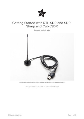
1. PurposeThis specification describes the protocol used to communicate with the SDR-IQ digital receiver. The protocol isbased on a more generic protocol called ASCP(Amateur Station Control Protocol).2. Basic Protocol ConceptsDefinitions used in this specification:In the case of the SDR-IQ, the host is the PC and the Target device is the SDR-IQ hardware.Host The main initiator of communications. Typically would be a PC or other computer system such as a customuser interface controller.Target The device that is to be controlled or monitored by the Host.Control Item The value, setting, or state of the target that is to be controlled or monitored by the Host. Forexample Frequency, Antenna direction, modulation mode, transmitter state, etc.TargetHostControl Item(Sidebandmode)Control Item(Frequency)ControlApplicationProgramControl Item(IFFilterShape)Control Item(PTT State)Data Item Digital data associated with the received or transmitted signal. This could be digitized audio, IF,frequency domain data(FFT), information data such as text or AX25 data, etc.Message Block A contiguous block of bytes comprising a single Control Item or Data Item transfer from target tohost or host to target.To simplify the protocol, the link can only comprise one host and one target. The Host is the only one that can set orrequest Control items. This means a Target device cannot connect to another target device or daisy chain to othertargets. The Host can control multiple Targets by utilizing multiple links such as USB endpoints or multiple TCP/IPSockets.Ver. 1.04 2013-12-184
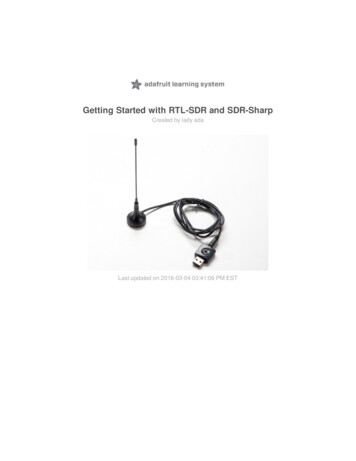
HostHostTarget1TargetTarget2Application ProgramHost1Link1Target1Host2Link2Target2The protocol allows a Target to send unsolicited Control Item messages to the Host. This is desirable for updatingthe Host when a something changes in the Target without the need for polling by the Host. An example would be when auser changes the frequency of the radio using the radio's frequency knob. The target can send the updated frequency asit occurs without requiring the Host to ask for it.Message blocks contain the block length in the message header. This is useful to aid in decoding messages as wellas being able to support variable length Control Items. For example, a Control Item containing the text string for theTarget's manufacturer and model number can be different lengths.The protocol contains a mechanism for obtaining information about the range and resolution of a Control Item. Thisallows the Host to obtain the limits of Control Items for the particular target device. For example, the frequency ranges ofthe target as well as the frequency step size can be obtained without any knowledge of the model or manufacturer of theradio. This capability is key in being able to write a generic application interface program without having to maintain a listof all possible radios and devices that may be connected.Target devices are not required to implement all the functionality of the protocol. A simple Target device that turnson and off a light need only implement the single Control Item message associated with it. This allows micro controllerswith limited capability to be used.The Data Item message blocks allow various raw data blocks to be sent and received along with the Control Itemsover the same physical link. The Header type allows up to 4 logical channels of data to be specified in each direction.This permits sending digitized audio, digitized I/Q IF data, etc. to and from a target over the same physical connection.Note that there is no synchronization or error handling mechanism in this protocol. This layer of protocol assumesthat the block synchronization and error handling is done at a lower level. This is a reasonable assumption sinceVer. 1.04 2013-12-185
Ethernet, USB, IEEE 1394, and most other modern physical links provide error recovery. The exception is RS232 seriallinks. This protocol will work over it as-is but if any data corruption is anticipated, then some simple method such as"SLIP" should be used to frame the data bytes and perhaps add error detection as well. A little "sanity" checking ofmessage block parameters can be used as a simple error detection scheme and allow the RS232 system to eventuallysync back up. Adding a timeout will handle the case where a link is disconnected in the middle of a transfer. Since RS232serial links are being phased out, it doesn't make sense to burden a protocol to handle such a legacy physical link.3. Message Block FormatThe basic message structure starts with a 16 bit header that contains the length of the block in bytes and also a 3 bittype field. If the message is a Control Item, then a 16 bit Control Item code follows the header and contains the codedescribing the object of the message block. This is followed by an optional number of parameter or data bytes associatedwith this message. The byte order for all fields greater than 8 bits is "Little Endian" or least significant byte first.Control Item Message block format:16 bit Header(lsb msb)16 bit Control Item(lsb msb)Parameter BytesData Item Message block format:16 bit Header(lsb msb)N-Data BytesThe 16 bit header is defined as follows:8 bit Length lsb3 bit type5 bit Length msbThe 13 bit Length parameter value is the total number of bytes in the message including this header. The range ofthe message Length is 0 to 8191 bytes.A special case for Data Items is that a message length of Zero is used to specify an actual message length of 8194bytes(8192 data bytes 2 header bytes). This allows data blocks of a power of 2 to be used which is useful in dealingwith FFT data.Ver. 1.04 2013-12-186
The message type field is used by the receiving side to determine how to process this message block. It has adifferent meaning depending upon whether the message is from the Host or Target.3 bit MsgType 111Ver. 1.04 getMessage TypeSet Control ItemRequest Current Control ItemRequest Control Item RangeData Item ACK from Host to TargetHost Data Item 0Host Data Item 1Host Data Item 2Host Data Item 3Response to Set or Request Current Control ItemUnsolicited Control ItemResponse to Request Control Item RangeData Item ACK from Target to HostTarget Data Item 0Target Data Item 1Target Data Item 2Target Data Item 37
3.1. Detailed Description of the Message Block Types and Their Purpose3.1.1 Set Control ItemThis Message type is sent from the Host to the Target requesting that the Target change the specified Control Item tothe new value supplied in this message. A request to change to a new frequency would be an example of this type ofmessage. The Target must respond to this message.3.1.2 Request Control ItemThis Message type is sent from the Host to the Target requesting that the Target respond with its current state orvalue of the specified Control Item of this message. A request to get the current S-meter reading would be an example ofthis message type. The Target must respond to this message.3.1.3 Request Control Item RangeThis Message type is sent from the Host to the Target requesting that the Target respond with the acceptable rangeof values of the Control Item supplied in this message. A request for the targets frequency range(s) and step sizes wouldbe an example of this message type. The Target must respond to this message.3.1.4 Response to Set or Request Current Control ItemThis Message type is sent from the Target to the Host in response to a request from the Host to either set or justreturn the current value of the Control Item supplied in this message. This message contains the current value of theControl Item. It is sent in response to either the "Set Control Item" or "Request Control Item" message.3.1.5 Unsolicited Control ItemThis Message type can be sent from the Target to the Host without any request from the Host. It contains the currentvalue of the Control Item supplied in this message. This message can be sent at any time to the Host. It can be used toupdate the Host to any changes that have occurred in the Target Control Items. An example would be if the user changedfrequency using the Targets frequency knob, then the Target could send the new Control Item value to the Host withouthaving to wait for the Host to ask for it. There is no response back from the Host when this message is received.3.1.6 Response to Request Control Item RangeThis Message is sent from the Target to the Host in response to a "Request Control Item Range" message from theHost. It contains the allowable range and step size of the Control Item supplied in this message.3.1.7 Data Item MessagesData Item message allow data messages to be allocated to different logical "channels". Different types of datablocks may be interleaved together and this mechanism allows each end to keep the data separated. For example, DataItem 2 blocks may be digitized audio from a Target receiver that needs to be processed and sent to a soundcard speaker.Data Item 3 Blocks may be spectral data from an FFT inside the Target receiver that needs to be sent to the Hostapplications display screen.The current scheme allows up to four different logical channels for each data direction.Ver. 1.04 2013-12-188
3.2. The ACK and NAK Messages and Their PurposeA "NAK" message is a 16 bit header without a Control Item or parameters (Message length of 2) . When the NAKmessage block is returned by the Target, it indicates that the specified Control Item is not supported. This allows a targetto implement only the Control Items it actually needs. Any Host message requesting an unimplemented Control Item willbe returned the NAK message. The Host can then exclude this Control Item from its list of Items to control or monitor.As an example, suppose a Host requests the elevation setting from a rotor Target controller that only supportsazimuth readings. The Target controller would just return the NAK header.Implementation on the Target side is easily done by simply decoding only the Control Item messages that it supportsand returning the NAK for all others.On the Host side, one could initially poll the Target for all the Control Items it may use and then tag the ones thatreturn NAK for exclusion.This dynamically allocated feature set allows application software to determine on the fly what capabilities areavailable without any prior knowledge of the Target device.A Data Item "ACK" message is a 16 bit header with a Message Type 011b with a single parameter byte specifyingthe Data Item (0 to 3). The 16 bit header is a fixed value (0000 0011 0110 0000 0x0360 ). The parameter bytefollowing the header specifies which Data Item block that is being ACK'd.For example if the Target received a block of Data Item 2 data correctly it could send the following back to the Host:[03][60] [02]The ACK response messages is to provide handshaking to data item transfers. If a data item message is receivedcorrectly then an ACK response message could be sent back to the sender. This implementation is optional as one maywant to stream data without error checking or only ACK periodically the data stream.Ver. 1.04 2013-12-189
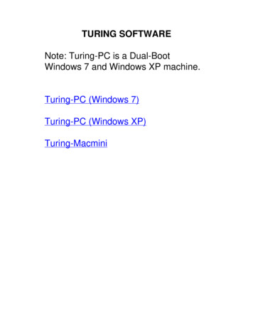
4. SDR-IQ Architecture4.1. Block DiagramBNCRF In( 500Hz to 30MHz )66.666MHzClk5 MHzLPF0 / -10dBAttenuator15 MHzLPF5 MHzHPF6 to 34 dB30 MHzLPF15 MHzHPF14 BitA/D40 MHzLPFAD8370PreampA D9 2 4 5ProtectionClipDetectControl BusAnalog DevicesAD6620DDCJTAGDebugPortSDR-IQBlock DiagramAtmelAT91SAM7S256uC64K RAM256K FLASHSerial I/Q DataActivityControl and USB Data Bus 2006 RFSpace Inc.PowerVoltageRegsPowerControlFTDIFT245RLUSB 2.0Full SpeedInt/Ext Timed Capture SyncRS232LevelConverterRS232DTEDE9M4.2. FunctionalityThe SDR-IQ consists of a selectable attenuator, a bank of filters, a preamp, a 14 bit A/D converter sampling at66.66667MHz, a digital down converter, an ARM7 Microcontroller, and a USB interface.The 14 bit data from the A/D converter is passed to the input to an Analog Devices (http://www.analog.com/) AD6620digital down converter chip. This chip contains a digital mixer which converts the real input data into two separate datastreams of I and Q data. An NCO (Numerically Controlled Oscillator) can be programmed with the desired downconverter center frequency from 0 to 30MHz with a 1Hz step size. The AD6620 also contains three programmabledecimation stages to reduce the sample rate as well as a FIR filter to provide band pass filtering on the decimated data.The data from wither the A/D or down converter chip is sent via a serial link to an Atmel AT91SAM7S256 ARM7Microcontroller. Data is packetized and sent out over the USB interface.4.3. FTDI USB interfaceThe USB interface of the SDR-IQ is provided by an interface chip manufactured by FTDI (http://www.ftdichip.com/).The chip implements the low level USB protocol stack in hardware and provides the basic data connection to the SDR-IQ.FTDI provides a Windows driver for the FT245RL chip and so the low level USB interface is hidden from theapplication software writer. The driver provides basic read and write functions that are then used to implement the actualVer. 1.04 2013-12-1810
SDR-IQ interface protocol. Please refer to the FTDI driver documentation for the function specifications and also examplecode.The generic driver provided by FTDI is used as the interface to the PC host.5. SDR-IQ Control Item DefinitionsAll examples use hexadecimal notation within brackets [] for the individual byte values.The "Target" referred to is the SDR-IQ unit.5.1. General Control Items5.1.1 Target NamePurpose: Returns an ASCII string describing the Target device.Control Item Code : 0x0001Control Item Parameter Format: The data is a NULL(zero) terminated character byte string.Example, to request the target name, the host sends:[04][20] [01][00]The Target responds with "SDR-IQ" :[0B][00] [01]00] [53][44][52][2D][31][34][00]Example of Obtaining Target Name0x040x20 0x010x00PC Sends0x0B 0x00 0x01 0x00'S' 'D' 'R' '-''1' '4'0x00SDR-14Replies5.1.2 Target Serial NumberPurpose: Contains an ASCII string containing the Target device serial number.Control Item Code : 0x0002Control Item Parameter Format: The data is a NULL(zero) terminated character byte string.Example, to request the target serial number the host sends:[04][20] [02][00]The Target responds with "MT123456" or the serial number the particular device:[0C][00] [02]00] [4D][54][31][32]33][34[35[36][00]5.1.3 Interface VersionPurpose: Contains the version number of the Host or Targets implemented Interface. This allows the Host or Targetto display or adapt to different versions of the interface.Ver. 1.04 2013-12-1811
Control Item Code: 0x0003Control Item Parameter Format: The data is a 2 byte 16 bit unsigned variable equal to the version times 100. Forexample the value 123 would be version 1.23.Example, to request the target interface version the host sends:[04][20] [03][00]The Target with an interface version of 5.29 responds with:[06][00] [03]00] [11][02]Ver. 1.04 2013-12-1812
5.1.4 Hardware/Firmware VersionsPurpose: Contains the Firmware or Hardware version information of the Target.Control Item Code: 0x0004Control Item Parameter Format:The first parameter is a 1 byte Firmware ID specifying which firmware or hardware version to retrieve.ID 0 returns the PIC boot code version.ID 1 returns the PIC firmware version.The version data is a 2 byte 16 bit unsigned variable equal to the version times 100. For example the value 123would be version 1.23.Example, to request the PIC firmware version host sends:[05][20] [04][00] [01]The Target with a PIC firmware version of 5.29 responds with:[07][00] [04]00] [01] [11][02]Example, to request the PIC boot code version host sends:[05][20] [04][00] [00]The Target with a PIC firmware version of 5.29 responds with:[07][00] [04]00] [00] [11][02]5.1.5 Status/Error CodePurpose: Contains the Error/Status code(s) of the Target. This item is used to notify the Host of any error orproblem using a list of code values. Once the error code(s) are obtained, the host can interrogate the Target "ErrorString" Control Item to obtain a description string of the error(s) or status.Control Item Code: 0x0005Control Item Parameter Format: The data is a list of 1 byte unsigned variable equal to the error number associatedwith a particular error. There can be multiple error codes returned by the Target.0x0B SDR-IQ Idle0x0C SDR-IQ Busy(capturing data)0x0D SDR-IQ Loading AD6620 parameters0x0E SDR-IQ Boot mode Idle0x0F SDR-IQ Boot mode busy programming0x20 SDR-IQ A/D overload occurred0x80 SDR-IQ Boot mode programming errorExample, host request status:[04][20] [05][00]The idle Target responds with[05][00] [05]00] [0B]5.1.6 Product ID (Firmware 1.04 or Greater)Purpose: Returns the 4 byte product ID for the SDR-IQ used in firmware update validation.Control Item Code: 0x0009Control Item Parameter Format:A read only value returned identifying the SDR-IQ.Example, host request product ID:[04][20] [09][00]The Target responds with[08][00] [09][00] [00][A5][FF][5A]Ver. 1.04 2013-12-1813
5.1.7 Security Code (Firmware 1.04 or Greater)Purpose: Returns 32 bit Security code based on 32 bit security key.Control Item Code: 0x000BControl Item Parameter Format:The first parameter is 4 byte security key provided by host. The SDR-IQ then returns a 4 security code that isformed by an encryption algorithm unique to the SDR-IQ. Please contact RFSPACE for details on the algorithm. This is away to protect host software from being used on other hardware.Example, host requests Security code for a key of 0x12345678:[08][20] [0B][00] [78] [56] [34] [12]The Target responds with a 4 byte security code[08][00] [0B][00] [xx][xx][xx][xx]5.2. SDR-IQ Receiver Control Items5.2.1 Receiver StatePurpose: Controls the operational state of the SDR-IQ and specifies the input channel.Control Item Code: 0x0018Control Item Parameter Format:The first parameter is a 1 byte receiver channel ID ( 0x81 is only allowable value).ID 0x81 (AD6620 complex data mode) RF Filters followed by a Preamp then the A/DThe second parameter is a 1 byte value defined as:0x01 Idle(Stop)0x02 Run.The third parameter is a 1 byte parameter specifying the capture mode.0 Contiguous mode where the data is contiguously sent back to the Host.2 One Shot mode where N blocks of 8192 bytes of data is sent back to the Host3 HW Synced Trigger mode where N blocks of 8192 bytes of data is sent back to the Host after theHW sync is pulsed, then the SDR-IQ waits for the next HW sync pulse then the next N blocks are sent.The fourth parameter is N, the number of blocks requested to be sent after a HW trigger.Range is 1 to 128. Value is ignored for Contiguous mode. Each block is a Data Item of 8192 bytes.(HW Trigger mode supported with Firmware 1.04 or greater)Ver. 1.04 2013-12-1814
Example: Request to start the SDR-IQ capturing data in the contiguous mode on channel 0x81.The host sends:[08][00] [18][00] [81] [02] [00] [01]The Target responds with:[08][00] [18]00] [81] [02] [00] [01]Example of Starting and Stopping the SDR-IQ in Contiguous ModeTo startPC SendsSDR-IQResponds#msg #msgbytes type0x08 0x000x080x00Receiver State InputControl ItemChannel0x18 0x000x810x18 gnored0x010x01.SDR-IQ begins sending Data Messages back to PCTo stopPC SendsSDR-IQResponds#msg #msgbytes type0x08 0x000x080x00Receiver State InputControl Item Channel0x18 0x000x810x18 00x01SDR-IQ stops sending Data Messages back to PCIn the One Shot data mode after the specified number of data blocks has been sent, the SDR-IQ sends an anunsolicited Receiver State IDLE message back to the host. The SDR-IQ then stops and goes back to idle mode. Thismode can be used to get a number of blocks once without having to tell the SDR-IQ to stop.Example: Request to start the SDR-IQ capturing 4 blocks of data in the one shot mode before going back to idle.The host sends:[08][00] [18][00] [81] [02] [02] [04]The Target responds with:[08][00] [18][00] [81] [02] [02] [04]Ver. 1.04 2013-12-1815
Example of Starting the SDR-IQ in One Shot ModeTo startPC SendsSDR-IQResponds#msg #msgbytes type0x08 0x000x080x00Receiver State InputControl ItemChannel0x18 0x000x810x18 0x000x81RUNcmd0x02OneShotMode0x020x020x02#Blocksto get0x040x04.SDR-IQ begins sending 4 Data Blocks back to PCUnsolicitedReceive StateIdle Msg0x080x200x18 0x000x810x010x020x00Target sends unsolicited Receive state idle message after last data blockVer. 1.04 2013-12-1816
5.2.2 Receiver FrequencyPurpose: Controls the SDR-IQ NCO center frequency.Control Item Code: 0x0020Control Item Parameter Format:The first parameter is a 1 byte receiver channel ID ( 0 to 3). This parameter is ignored.Followed by a 5 byte frequency value in Hz(32 bit unsigned integer LSB first)The range of this number must be 0 to 33,333,333HzThe fifth upper frequency byte is ignored.Example, To set The SDR-IQ NCO frequency to 14.010 MHz.The host sends this:[0A][00] [20][00] [00] [90][C6][D5][00] [00]The Target responds with:[0A][00] [20][00] [00] [90][C6][D5][00] [00]Example, To get the current NCO frequency:The host sends this:[05][20] [20][00] [00]The Target responds with:[0A][00] [20][00] [00] [90][C6][D5][00] [00]Example, To get the available SDR-IQ frequency range:The host sends this( the channel ID parameter is ignored):[05][40] [20][00] [00]The Target responds with:1 byte channel ID (ignored)The frequency range consisting of 10 bytes5 byte Frequency min (hard coded to 0)5 byte Frequency max (hard coded to 30MHz)[0F][40] [20][00] [00] [00][00][00][00][00] [80][C3][C9][01][00]5.2.3SDR-IQ A/D Input Sample RatePurpose: Specifies the SDR-IQ input sample rate.Control Item Code: B0Control Item Parameter Format:The first parameter is a 1 byte receiver channel ID ( 0 to 3). This parameter is ignored.The following 4 byte parameter specifies the input source sample rate in Hz.The SDR-IQ nominally has a sample rate of 66,666,667Hz. This command can be used to specify the actual samplerate so that the frequency can be set more accurately.Note, this does not change the sample rate but is a way to tell
This specification describes the protocol used to communicate with the SDR-IQ digital receiver. The protocol is based on a more generic protocol called ASCP(Amateur Station Control Protocol). 2.Basic Protocol Concepts Definitions used in this specification: In the case of the SDR-IQ, the host is the PC and the Target device is the SDR-IQ hardware.