Transcription
MOUNTING ACCESSORIES &ENGINEERING DATAUNITTOOL Punch & Die Company Inc.20 Norris St. Buffalo, New York 14207 Phone: 1-716-873-8453 Fax: (USA Only) 1-800-25Punch (257-8624)Email:Info@Unittool.com1
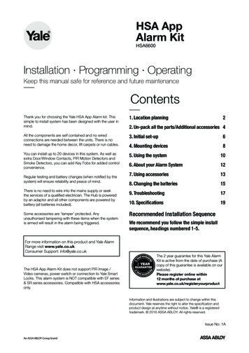
UNITTOOLMOUNTING ACCESSORIESRam striker plateRAM STRIKER PLATE PROVIDES ADDITIONALSTRIKING AREA FOR PRESS BRAKE OPERATIONManufactured in 4, 5 and 6 footlengths. When multiple lengthsare used–ask for squared ends.(Price on application.)CAT. NO.BedrailCAT. NO. BR-800WEIGHT 36# PER FT.RP-802RP-803RP-804RP-805ABWT.PER FT./43/41/22655416149293FOR USE WITH STRIPTEMPLATE OR BEDRAIL SPACERS.Any template width up to 6" may be used. For template widerthan 43/4", remove 3/8" wide bedrail space bar. Bedrails aremanufactured in 4, 6, 8, 10 & 12 foot lengths. When multiple lengths are used, ask for ends to be machined for butting. (Price on application.) “C” Frame units with 8" depth orgreater are recommended for use with bedrail.BedrailCAT. NO. BR-801WEIGHT 63# PER FT.FOR USE WITH FORMINGDIE, TEMPLATE OR BEDRAIL SPACERS.Eliminates need to remove bedrail for forming operations.Any template up to 6" may be used. For template wider than43/4", remove 3/8" wide bedrail spacer bar.Manufactured in 4, 6, 8, 10 & 12 foot lengths. When multiplelengths are used, ask for ends to be machines for butting.(Price on application.) “C” Frame units with 8" or greater arerecommended for use with bedrail.Bedrail spacers2CAT. "FOR USE WITHHeavy & Medium Duty Units up to 11/4" width.Heavy & Medium Duty Units from 11/4" to 2" width.Heavy & Medium Duty Units from 2" to 3" width.Heavy & Medium Duty Units from 3" to 31/2" width.Heavy & Medium Duty Units from 31/2" to 53/4" width.Heavy & Medium Duty Units from 53/4" to 8" width.Adjustable End Stop - Cat. No. 828 & 829.All Series 200 Corner & Edge Notching Units.All Series 100 - 3x3 & 5x5 Corner Notching Units.For convenient mounting of units on bed rail when templateis not used. Spacers can be adjusted along the rail to suit anyparticular hole pattern.
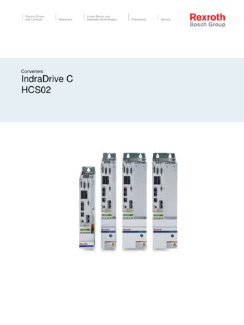
AdjustableWork stopA 11/4"A 1"Adjustable work stop sitson plate for template or teeslotted plates. The verticalpin can be removed andthe screw can be adjustedfor variations in stockCAT. NO. WS-818 dimensions.CAT. NO. WS-819Dowel pin stopCAT. NO. WS-820FOR “H” SERIES CAT. NO. HWS-822FOR “M” SERIES CAT. NO. MWS-823Disappearingpin stopSpringloadedpick-up pinFOR “H” SERIES CAT. NO. HWS-824FOR “M” SERIES CAT. NO. MWS-825For relocatingfrom previouspierced hole.FOR “H” SERIES CAT. NO. HWS-824FOR “M” SERIES CAT. NO. MWS-825For a positive stoplocation with adjustmentfeature to compensatefor variations in size ofwork piece.TRAVELCAT. NO. WS-873Disc edgestopFor progressivepiercing whenusing edge of sheetfor gauging.Fixedpick-uppinFor use on templates orTee slotted plates.AdjustablestopFor popular use forfixed stop on mountingtemplateCAT. NO. WS-821GeneralpurposestopFOR “H” SERIES CAT. NO. HWS-826FOR “M” SERIES CAT. NO. MWS-827For end gauging thework piece within the ‘C’frame holder.Disc only:Cat. No. Ws-874For locating from holespreviously punchedwhen performing passalong operations.Bolt and washer setFeed rail and adjustable stopFOR “H” SERIES A 31/2FOR “M” SERIES A 219/32CAT. NO. HFR-830CAT. NO. MFR-831Feed Rail OnlyFOR “H” SERIES A 31/2FOR “M” SERIES A 219/32CAT. NO. HFR-832CAT. NO. MFR-833Feed rails are used to supportwork piece over large spansbetween punching units.Adjustable Stop OnlyCAT. NO. FRS-834A 3"-B 1/2-13 CAT. NO. BW 863 –FOR MODEL H51/4 & H8 UNITSA 21/4"-B 1/2-13 CAT. NO. BW 842 – FOR MODEL M & H UNITSEXCEPT H-53/4, H-8, HH-51/2 & M-3/4A 21/4"-B 5/16-18 CAT. NO. BW 864 – FOR MODEL M3/4 UNITFor template mountingA 31/2"-B 1/2 CAT. NO. NBW 865 – FOR MODEL H5¾ & H8 UNITSA 3"-B 1/2 CAT. NO. NBW 843 – FOR MODEL M & H UNITSEXCEPT H-53/4, H-8, HH-51/2 & M-3/4A 21/2"-B 5/16" CAT. NO. NBW 866 – FOR MODEL M-3/4 UNITSA 31/2"-B 1/2" CAT. NO. NBW 872 SQ. HEAD TEE BOLT SETTeebolt,nutandwashersetThe base of the tee bolt is designed so itcan be dropped into the tee slot at anylocation. When the nut is tightened, thebase of the bolt automatically swings intoplace for tightening. NBW-872 squarehead tee bolt must slide in from end ofthe tee slot.3
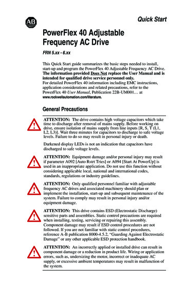
Tee slotted plateWidthNo. of SlotsUnittool’s tee slotted platesare used for mounting unitsin press brakes or stampingpresses. When multiplelengths are used – ask forends to be “squared.” Priceon application.12182430366 TSP-12189 TSP-1818121518-243036486072144Approx.Poundsper Footof 142170LENGTH AND CATALOG NO.18Locator pinsCat. No.ALP 835LP 836.312.375LP 837.4375LP 838LP 839.500.625LP 840.875LP 8411.000Grind lifeFor Use withmodelL - series, M /4M 11/4H-1, HP 1, HA 1H 11/4, HP 11/4,HA 11/4M-13/4H 11/2 - HP 11/2 HA 11/2H 2, HP 2,HA 2, HM 21/43Locator pins are used to setup units on a tee slotter plateor bolster. A sheet metaltemplate is placed on thedie section of the unit. Thelocator is dropped downthrough the guide to pickup the hole in the template.The unit is then bolted inposition. The locator pin isremoved and the punch isreplaced in the guide.Punch and die grind life must not exceed the dimension shown. The stripper springs and holder canbe severely damaged if punches and dies are used without shims beyond the recommended grind life.See below for shim information.MEDIUM DUTYHEAVY-DUTYMODEL NO.H1 thru H2HP-1 thru HP-2HA-1 thru HA-2H-21/2HP-21/2H-3, 8–––3MODELAPunch Ass’yLength withHeadM-3/42.906M-12.906M-11/4, 13/4, 21/4 2.906M21/2, M-32.906M-42.906M-52.906M-82.906Punch and die shims 1/16" THICKNESSPunch and die life can be extended greatly byuse of shims to bring parts up to “new” length.(For punch and die length when new, seecharts above). Punch shims can also be usedto lengthen punches in event it is desirable tostagger punching load.PUNCH(“M” series only).DIE4BCPunchLengthDiew/o Head ERPS-845M 3/4MP 072PS 846M 1-1/4MP 122PS 847M 1-3/4MP 172PS 848M 2-1/4MP 222PS 849M3MP 302-1(FOR PUNCH TIP SIZE UNDER 1.125)PS 850M3MP 302(FOR PUNCH TIP SIZE OVER 1.125)PS 851M 5 & H 5-3/4 MP 502 ABC&DPS 852M 2-1/2HP 252PS 853H 3-1/2HP 352CATALOGFORDIENUMBERMODELNUMBERDS 854M 3/4MD 073DS 849M 1-1/4MD 123DS 848M 1-3/4MD 173DS 855M 2-1/4MD 223DS 856M3HD 303DS 857M 5 & H 5-3/4 HD 603DS 858H 1 & H 1-1/4 HD 123DS 859H 1-1/2HD 153DS 860H2HD 203DS 861H 2-1/2HD 253DS 862H 3-1/2HD 253
Magnetic work stopFULLYADJUSTABLERADIALLY &VERTICALLYCAT. NO. MWS 868Magnetic Work Stops help to insure accurate gauging byeliminating “bounce back.” Also eliminates the need for theoperator to hold work piece against stop during press cycle.Recommended by OSHA.SUITABLE FOR 3-1/2" DIE HEIGHT (Heavy-Duty) or2-19/32 DIE HEIGHT (Medium Duty).Special wrenchA Special Wrench designed to drop through slot inupper section of holder for easy access to hex nut onthe tee slot bolt when units are on close centers.WRENCH – CAT. NO. W. 869Magnetic Feed RailsCatalog No.DescriptionHFRM-870Magnetic Feed Rail(Heavy Duty)MFRM-871Magnetic Feed Rail(Medium Duty)Magnetic work supporting feed rails are nowavailable for use with heavy and medium dutypunching and notching systems. This rail virtuallyeliminates template location and set up time. Torelease the magnetic force simply lift the magneticfeed rail away from the template or tee slot plate.Compensator caps for H1, H11/4, H11/2 & H2 units.Compensator Caps are used to stagger punching load whenavailable press tonnage is marginal. The caps alter the punchassembly length and cause the punch tips to enter the materialat different intervals, thereby reducing the required tonnageaccordingly. The disadvantage of using compensator caps isthat it overworks the stripping springs because of additionalpunch assembly length. Caution must be exercised toprevent “bottoming.” New or full length punches and dies arerecommended when using compensator caps in order to keep thepress shut height at a maximum.BCPART NO.H1, 0-0621/8CC-200-125H2A21-17/31CHART TO SHOW HOW DIFFERENTCOMBINATIONS CAN BE USED:MaterialThickness ToBe 61/81/16 & 1/8Approx. % ofFull TonnageReqd50505033-1/33/163/161/161/850503/161/16 & 1/833-1/31/4*1/4*1/81/16 & 1/85040* Use extreme caution on1/4" materialNumber ofPunchesCapped1/2 (50%)1/2 (50%)1/2 (50%)2/3 (66.6%)1/3 w 1/16"Cap1/3 w 1/8"Cap1/2 (50%)1/2 (50%)2/3 (66.6%)1/3 w 1/16"Cap1/3 w 1/8"Cap1/2 (50%)2/3 (66.6%)1/3 w 1/16"Cap1/3 w 1/8"Cap5
Punch adapter guides for H-seriesPunch Adapter Guides are used to convert a larger unit foruse with smaller and less expensive punches. For example:the HPA-122A punch assembly for the H1¼ unit can be usedin the H1½ or H2 unit for punching hole sizes of 7/16" andsmaller – the HPA-152A punch can be used in the H2 unitfor punching hole sizes 5/8" and smaller – a savings of 10%to 50% can be realized with this method.The Punch Adapter Guides are available for round or shapedhole punches. The only components required to convert alarger unit for use of smaller punches are: Punch AdapterGuide, Punch and Head Assembly and Stripper Spring.Punch AdapterGuide NumberFORROUNDHOLEUNITFORSHAPEDHOLEUNITAdapts Punch Assembly NumberFor Use withMax. Punch Tip Use StripperPunch AssemblyDimensionSpring NumberSHG-122-154HPA-122A from H11/4 Holder to H11/2 HolderHPA-122A.4375HSS-125SHG-122-204HPA-122A from H1 /4 Holder to H2 HolderHPA-122A.4375HSS-125SHG-152-204HPA-152A from H1 /2 Holder to H2 HolderHPA-152A.625HSS-155SHG-122-154KHPA-122K from H1 /4K Holder to H1 /2K HolderHPA-122K.4375HSS-125SHG-122-204KHPA-122K from H1 /4K Holder to H2K HolderHPA-122K.4375HSS-125SHG-152-204KHPA-152K from H1 /2K Holder to H2K HolderHPA-152K.625HSS-155111111Increased stripping pressure forHeavy-Duty 1", 11/4" & 11/2" unitsIllustration shows Model H11/2"with HSS-205 Spring andSPH-152-207 Punch Head.Outside OutsidePercentageWidth Diameter DiameterOversizeofofofofSpringIncreasedHolder Regular OversizeNumberPressureSpringSpringH-1, HA-1 & HP-11111/450%HSS-125H-1, HA-1 & HP-1111 /2170%HSS-155H-11/4, HA-11/4 & HP-11/411/411/411/280%HSS-155H-11/2, HA-11/2 & ral SPH-122-157SPH-122-157SPH-152-207Increased stripping pressure can be made available by adapting the unit with oversize springsthat are larger than standard springs on the outside diameter. Special oversize punch headsare also required to properly center the spring around the punch shank. (The spring andpunch head exceed the width of the “C” frame holder.)Electrical push button punches & diesCutler-HammerSpringPriceSee Heavy DutyPrice Sheet underH-11/4, H-11/2 & H-2FORMODELNUMBERSquare-DWestinghouseGeneral ElectricDimensions shown are standards listedby Push Button manufacturers.Allis ChalmersFurnas ElectricGeneral Electric Miniature
SHAPED HOLE PUNCHES, DIES & GUIDESStandard ShapesStandard shapes are keyed for bothparallel and 90 degree position to thecenter line of the holder.Semi standard and special shapesSEND SKETCHFOR PRICE QUOTATIONNOTE: For Shapes that are not symmetrical – specify location ofshape in relation to center line of holder so that punches and diescan be properly keyed. Listed below are examples of common special shapes. When ordering, please submit a sketch with dimensions as shown. Also specify material thickness being punchedand keying information by (point-X) in relation to the front ofthe machine.When ordering shaped punches and dies for any keyedholder, specify by placing suffix “K” after the round holecatalog number. Also forward description and/ or sketchwith complete dimensions of shape – type and thicknessof material to be punched or die size.When ordering keyed punchguides, required for shaped holemissing punching – specify byplacing the suffix “K” after theround hole catalog number.EXAMPLE:HP 152HPA 152KPUNCH (ROUND HOLESHAPED PUNCH ASS’Y.1875 x .375 RECTANGLEEXAMPLE:HP 153HPA 153KDIE (ROUND HOLE)SHAPED DIE.194 x .381 RECTANGLEEXAMPLE:GUIDE (FOR ROUND HOLEPUNCHING)KEYED GUIDE (FOR ROUND &SHAPED HOLE PUNCHING)HP 154HPA 154K7
Press brakemounting informationShown below are various mounting arrangementsthat may be helpful in determining the best methodfor your application.See Fig. 1This method requires a template that matches the hole patternof the part to be punched. The template is placed in the 4-7/8”wide recess of the Bed Rail. Bolting or securing the template tothe Bed Rail is not required. The template material is .500" thickcold rolled steel. Any width template from 1" to 4-3/4" may beused to suit the requirement. For template width from 4-3/4" to6" – remove the 3/8" wide keeper bar. The purpose of the 3/8"keeper bar is to provide a 4-7/8" wide retainer space when usingBed Rail Spacer as shown in Figure 2. (See page 1 for Bed RailSpacers.) The template is produced by drilling and reaming a.375 diameter pilot pin hole for each round hole to be punchedin the part. (Pilot pin is on the centerline of each “C” frame unit.)For shaped hole locations – drill and ream for 2 - .375" diameterpilot pins on 1.500" center. For economy reasons – a templatemay be provided with the hole pattern layout of more than onepart. In this case the holes are generally color coded or stenciledfor easy identification.Illustration to show Template or Base Plate setup withmedium duty Punching and Notching units.FIG. 2Illustration to show Bed RailNo. BR800 or BR801 withBed Rail Spacer that can beused instead of a template.Spacer can be adjustedalong the rail to suit a particular hole pattern. When usingthis method, we recommendthe use of 8" throat units orgreater, for maximum frontto back adjustment.FIG. 1FIG. 3Illustration to show howflanges can be added to thePress Ram to accommodatea wider striking area.(See Fg. 1 for Bed Rail Dimensions)FIG. 4Illustration to show anglesupports to adapt low shutheight presses to accommodate Heavy Duty “C”Frame Units. Not suitablefor Medium Duty “C” FrameUnits.FIG. 5Illustration to show LightDuty Units being mountedon BR100 Bed Rail. SeeLight Duty Catalog.8
ELECTRICAL KNOCKOUTCONDUIT HOLESExtruded hole data for #6, #8 and #10sheet metal screws or machine screwsFOR #6 SHEET METALOR MACHINE SCREWMETALTHICKNESS24 Ga.023922 Ga.029920 Ga.035918 Ga.047816 Ga.0598FOR #8 SHEET METALOR MACHINE SCREWMETALTHICKNESS24 Ga.023922 Ga.029920 Ga.035918 Ga.047816 Ga.0598B DIA.CAN BETAPPED FORMACH. SCREWS.169No.181No.193No.217Yes.241YesB DIA.SINGLE KNOCKOUTKnockout punches and dies can be furnished instandard units or for fabricating type machines. Thedies are furnished with a ‘kicker” to force the slugout of the die for easy removal of the material.CAN BETAPPED FORMACH. CATIONDOUBLE KNOCKOUTCONDUIT SIZEPUNCH SIZE FORSLIP FIT HOLE/8/23/411 1/41 1/222 1/2/16/81 1/81 3/81 3/422 1/2333 1/24563 5/84 1/84 5/85 5/86 3/43111FOR #10 SHEET METALOR MACHINE SCREWMETALTHICKNESS24 Ga.023922 Ga.029920 Ga.035918 Ga.047816 Ga.0598COUNTERSINK HOLES FORFLAT HEAD SCREWSB DIA.CAN BETAPPED FORMACH. IALUNITSSCREW SIZENO. 6NO. 8NO. 10M SERIES UNITM-11/4M-13/4M-13/4M-13/4M-21/4M-21/4H SERIES eDia.24 8.78922 5.79420 2.80018 6.81016 1.82214 2.83512 2.86310 9.8909
General InformationTOOL STEELS FOR PUNCHES AND DIESUnittool has standardized on Type O-1 Oil Hardening Tool Steel.This material has performed satisfactorily for most applications.Occasionally, tool steels of other characteristics may be required tosuit a particular application. Punches and dies, produced from thetool steels listed below are available – ask for quotation.Type M-2 (High Speed)Type D-2 (High Carbon – High Chrome)Type A-2 (5% Chrome)Type S-7 (Shock Resistant)PUNCHING INFORMATIONThe maximum hole size and material thickness for each punchingand notching unit is specified in the catalog. The metal thicknessrefers to SAE 1010-1020 – mild steel. Other materials may affectthe stripping, punching and/or notching ability of the equipment.Refer to tonnage chart on page 12 for tonnage requirement andshear strength of these materials. Listed below is other helpfulinformation.ALUMINIUM, COPPER & BRASSThese materials have a low shear strength and therefore cause a“drag” and “galling” effect. To help overcome this condition – keeppunches sharp and lubricate punch and work piece with a kerosene solution. The slugs have a tendency to fuse together whenpunching soft material. Take caution that slugs do not pile up inslug chutes. It is helpful to decrease die clearance to approximately75% of mild steel clearance.STAINLESS STEELThe shear strength of stainless steel is approximately 40% to 50%greater than mild steel depending on the physical properties ofthe material. The capacity of the punching or notching unit mustbe reduced accordingly. Punches and dies should be sharpenedmore frequently for good hole quality and also to eliminate tonnage“build up” due to additional forces required when punches and dieslose their keen cutting edges.RE-ROLLED RAIL STEELRe-rolled rail steel is one of the most difficult material to punchand notch due to extreme hard spots that cause breakdown ofthe punch and die cutting edges. In many cases, a particular areamay be harder than the punch. The material is unpredictable –some parts may punch satisfactorily and other parts may causeexcessive punch wear or breakage. Experience has proven thatpunches produced from M-2 (High Speed) tool steel give the mostsatisfactory results. Die buttons are generally subject to approximately 50% of the punch wear and therefore Unittool standardType O-1 oil hardening tool steel generally performs satisfactorilyfor medium protection.RULE OF THUMBThere is definite relationship or ratio that must be maintained between the thickness of material being punched and the minimumpunch tip diameter or hole size. The rule of thumb for punchingmild steel with a yield or shear strength of 50,000 P.S.I. is thatthe punch diameter must be equal to or greater than the materialthickness to be punched. This of course may be violated underproper conditions. For example: if a press brake or hydraulic pressis being used, the shock loads on the punch tips are greatly reduced as the punch enters the material; whereas, high speed mechanical presses create a greater shock load on the punch tip thatresult in greater failures.Dull punches and dies require greater punching pressure and mayresult in premature failure.10It is helpful in marginal operations to provide the punch tip witha shear ground face which will reduce the punching load on thepunch column. Special guided punch tips are also helpful in extending punch life.If material with less yield or shear strength is being punched –the thickness to diameter ratio may be altered to as much as 1 to2, (Example: 1/4" diameter hole in 1/2" material that has a yieldstrength of 25,000 P.S.I.) or even greater under ideal conditions.If the material has a yield strength of 75,000 P.S.I., the ratio mustbe reversed to approximately 2 to 1 (Example: 1/2" diameter holein 1/4" material).MAINTENANCE CHECKLISTMany times production will lag and quality will fall below standardbecause preventive maintenance has been neglected. It is thelittle things that develop into major problems which reflect highproduction costs. Productions costs can be decreased if your punching and notching equipment is properly maintained.You will find the following check list helpful in maintaining best performance of your Unittool equipment.REPLACEWORN SPRINGS!!CHECKLISTA – Excessive Burrs Result From:1. Dull punch and/or die2. Excessive die clearance3. Misalignment of “C” frame holderdue to fall or impact4. Press striker plate or bolster plateout of parallelB – Refusal to Strip Results From:NO HAMMERS!!1. Dull punch and/or die2. Insufficient die clearance3. Stock thickness in excess to unit capacity4. Press shut height below specifications5. Excessive galling of punch tip6. Irregular die heights when units are close together willwarp material while punching and cause “lock up” duringthe stripping action.7. Damaged stripper spring8. If punching material with scale or rust – the guides may bepacked with rust or scale particles that cause the punch tobind in the guide or may cause the guide to “hang up” inthe holderC – Spring Breakage Results From:1. Press shut height too low, causing springs to overstressor bottomD – Excessive Punch and/or Die Wear Result From:1. Holder out of alignment2. Material being punched has excessive hardness3. Striker plate is upset or not square to bed of press causingside load, thereby, throwing punch and die into shearE – “C” Frame Holder Out of Alignment Results From:1. Unit not supported properly2. Shut height too low, causing unit to bottom and close feedclearance3. Dirt or grit underneath holder4. Press ram and bed not parallel
Frequent QuestionsWHAT IS FEED CLEARANCE?WHAT IS SHUT HEIGHT?Shut Height for punching and notching equipment is the distance from the base of the unit to the ram of the press whenthe punch has entered the die.The Shut Height for a press is defined as the distance betweenthe bed and the ram when the stroke is down.WHAT IS DIE HEIGHT?Die Height is the distance from the base of the punching ornotching unit to the top of the die surface.Feed Clearance in a unit is the distance between the bottom ofthe guide and/or holder, and the top of the die when the pressstroke is up.WHAT IS DIE CLEARANCE?Die Clearance is the difference in size between the punch anddie. For example: if a punch size is .750" diameter and thedie size is .762" diameter, it has a total of .012" die clearance(.006" per side).For good hole quality, the die clearance should be increasedas the material thickness is increased and vice versa. Therecommended die clearance for unitized tooling is as follows:RECOMMENDED DIE CLEARANCE FOR UNITIZED TOOLINGoveroveroveroveroveroverUp to 1/16" Thick Mild Steel1/16" to 1/8" Thick Mild Steel1/6" to 3/16" Thick Mild Steel3/16" to 1/4" Thick Mild Steel1/4" to 3/8" Thick Mild Steel3/8" to 1/2" Thick Mild Steel1/2" to 3/4" Thick Mild Steel. . . . . . . .006 total.012 total.028 total.043 total.075 total.100 total.150 totalThe following drawings will show result of proper and excessive die SSIVECLEARANCEPENETRATIONSTART OFFRACTURECOMPLETIONOF FRACTURERESULT INSUBJECT PART11
United States Standard GaugeFRACTION AND DECIMAL 5.9375.953125.96875.9843751.USEFUL INFORMATION12To find circumference of a circle multiply diameter by 3.1416.To find diameter of a circle multiply circumference by .31831.To find area of a circle multiply square of diameter by .7854.Area of rectangle length multiplied by breadth. Doubling thediameter of a circle increases its area four times.To find area of a triangle multiply base by 1/2 perpendicular height.Area of ellipse product of both diameters x .7854.Area of parallelogram base x altitude.To find side of an inscribed square multiply diameter by 0.7071or multiply circumference by 0.2251 or divide circumferenceby 4.4428.(REVISED)Manufacturers’ Standard Gage for Sheet SteelBased on 0.0014945 in. per oz. per sq. ft.;0.023912 in. per lb. per sq. ft.(reciprocal of 41.820 lb. per sq. ft. per in. thick);3.443329 in. per lb. per sq. inStandardGage No.ThicknessInchesDecimalEquivalentOuncesperSq. FootDecimal Equivalents of Number Size DrillsNo.Size ofDrill inInchesNo.Size ofDrill inInchesNo.Size ofDrill .04650.04300.04200.04100.0400Decimal Equivalents of Letter Size DrillsLetterSize ofDrill inInchesLetterSize ofDrill inInchesLetterSize ofDrill 2500.2460.2420.2380.236.
CONVERSION CHART INCH/MMDrill No. 51462.5400Drill No. 84.64824.67364.69904.72444.74984.762
Grind life Punch and die shims 1/16" THICKNESS Locator pins Tee slotted plate Unittool's tee slotted plates are used for mounting units in press brakes or stamping presses. When multiple lengths are used - ask for ends to be "squared." Price on application. Locator pins are used to set up units on a tee slotter plate or bolster.