Transcription
HSA AppAlarm KitHSA6600Installation · Programming · OperatingKeep this manual safe for reference and future maintenanceContentsThank you for choosing the Yale HSA App Alarm kit. Thissimple to install system has been designed with the user inmind.1. Location planningAll the components are self contained and no wiredconnections are needed between the units. There is noneed to damage the home decor, lift carpets or run cables.3. Initial set-up64. Mounting devices8You can install up to 20 devices in this system. As well asextra Door/Window Contacts, PIR Motion Detectors andSmoke Detectors, you can add Key Fobs for added controlconvenience.5. Using the system106. About your Alarm System127. Using accessories138. Changing the batteries15There is no need to wire into the mains supply or seekthe services of a qualified electrician. The Hub is poweredby an adaptor and all other components are powered bybattery (all batteries included).9. Troubleshooting1710. Specifications19Some accessories are ‘tamper’ protected. Anyunauthorised tampering with these items when the systemis armed will result in the alarm being triggered.Recommended Installation SequenceRegular testing and battery changes (when notified by thesystem) will ensure reliability and peace of mind.2. Un-pack all the parts/Additional accessories 4We recommend you follow the simple installsequence, headings numbered 1-5.For more information on this product and Yale AlarmRange visit www.yale.co.ukConsumer Support: info@yale.co.ukThe HSA App Alarm Kit does not support PIR Image /Video cameras, power switch or connection to Yale SmartLocks. This alarm system is NOT compatible with EF series& SR series accessories. Compatible with HSA accessoriesonly.22The 2 year guarantee for this Yale AlarmKit is active from the date of purchase (Acopy of this guarantee is available on ourwebsite).Please register online within12 months of purchase atwww.yale.co.uk/registeryourproductInformation and illustrations are subject to change within thisdocument. Yale reserves the right to alter the specification andproduct design at anytime without notice. Yale is a registeredtrademark. 2016 ASSA ABLOY. All rights reserved.Issue No: 1A
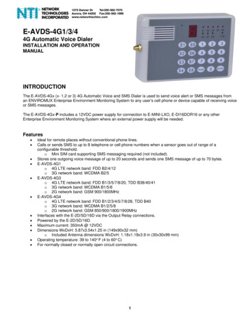
1Location PlanningWork out the best places to locate the devices for maximum protection. Having chosenthe locations do not mount at this stage.Home and Away Mode PlanningThe Home Arming mode allows the premises to be partarmed so that no one can get inside without warning theoccupier, yet the person already inside the house can movefreely without triggering the alarm. For example the downstairsof a house can be armed while upstairs can be disarmedallowing the user to go to bed without causing an alarm.If this feature is to be used, then it should be plannednow, before installation.Decide what areas can be occupied when in Home Armingmode, the sensors for these areas should have its attributeset to “Home Omit” (see page 10 and 12); and the sensorsactivated on the path to access the Key Pad should be to beset to “Home Access”.Key PadWhen used as a secondary Key Pad, it is ideal foruse in bedrooms or at the top of a stairwell so theground floor can be armed when going to bed forthe night, or, at a side or back door for alternativeentry point. Mount at chest height for ease of use Designed for indoor use only Key Pad should be accessible from a protectedentry/exit point Ensure that the Key Pad is not visible from theoutside of the premises.Operating RangeAll devices must be within 30 metres of the Hub and mustnot be mounted on or near large metal objects. Avoidobvious sources of electrical interference such as fridges andmicrowave ovens.Yale850When mounting devices ensure that any tamper switchesclose fully. On uneven surfaces it may be necessary to placepacking behind the switch for reliable operation.YaleExtend the SystemExtend the system in the future to increase your security or asyour needs change.For example, add extra PIR Motion Detectors andextra Door/Window Contacts. You can add upto 20 devices.Choosing LocationPanic ButtonThe Panic Button provides extra protection for youand your family. When help is needed the PanicButton can activate your alarm immediately - evenwhen the system is disarmed. Mount at chest height for ease of use Mount on flat wall surface Designed for indoor use only Out of reach of children Hidden from view while easily accessible.2274Tamper SwitchesTo minimise interference, avoid locating devices close to metalframework, glass, electrical appliances (especially wirelessdevices) and electric cables.Please note that the presence of high density material (metal,glass etc) in the transmission path will significantly reduce thewireless transmission range.1369
Smoke DetectorExternal Siren Mount in the middle of the ceiling at the top of astairwell, or on the centre of hallway ceilings wheresmoke would most likely be detected. Do not mount in corners or above cookingappliances and heaters. Install additional detectors if there are closed doorspreventing smoke from reaching detectors.Choose a position on an external wall where thesiren would be most prominent. Mount as high aspossible, out of easy reach.Door/Window ContactSelect a door that will be the main point of entry andexit, usually your front door. Mount as high as possible Do not aim a PIR at this door or windowKey FobCan be used inside or outside the property and canbe kept on your keyring.YaleY a leYalePIR Motion Detector Mount in a position such that an intruder wouldnormally move across the PIRs field of view. Height should be between 1.9 and 2 metresabove floor level. Location in a corner will ensure wider roomcoverage. Do not mount the PIR where its field of view will beobstructed e.g. by curtains, ornaments etc. Do not point directly at sources of heat e.g. fires orboilers, and do not position directlyabove radiators. Avoid mounting the PIR directly facing a window. Do not point the PIR at a door protected by aDoor/Window Contact.Hub This Hub is the brain of your AlarmSystem. All accessories wirelessly connectto the Hub. Ensure it is hidden from view. Access to mains socket and broadbandinternet router required.3
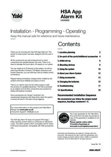
Smoke detecLearn/Testbutton21 Remove the cobatteries as shLEDUnpack all the tchMagnetSmoke detec2SmokeThe SmokededetecRemove thecalibration modbatteriesas shonormaloperatiRemovethebatteries as shoBatterysaver tabSensorHub1. Unpack the kit content on a table. Remove the mountingplate (if fitted) from the Hub by sliding plate downwards.A power adaptor is supplied that plugs into the main wallsocket and Hub. Plug in the power adaptor and connectthe Hub to your internet router using the cable provided.Door/window contactsDoor/windowcontactsKeyPad HSA60801 Remove the cover of each door/window contactKeypadremotecontrolby loosening the fixingscrew.Removethe coverof eachdoor/windowcontactPull21 outthetwoplasticsaverat detectorthe backof the KeyInsertAAAbatterybatteriesintotabeachasby looseningthe fixingscrew.Pad.Thiswillactivatethebatteries.1 Pullouttheplasticbatterysavertabatthebackofshown. The indicator LED will flash briefly.2 theInserttwo keypad.AAA batterieseach thedetectorasremoteThis willintoactivatebatteries.shown. The indicator LED will flash briefly.AExtension terminalsale terminalsYExtensionTamper 1switchTamper 4switchJumper 7switchArmJumperswitchBatterysaver tabYaleBRLearn rn/TestbuttonDisarm0HomeArmLearn/Test buttonLearn/Test buttonHelp button aHelpbuttonHelpbutton aRemove theRemovethe insecovscrew andRemove theandinsertPleasethe 12shown.screw and insePleaseensure yopolarity.shown. Pleasepolarity.Magnet2. In addition to the adaptor, there is a rechargeablebattery inside the Hub that serves as a backup in caseof a power failure. A fully charged battery can providebackup standby power for a period of approximately 2hours. It takes approximately 72 hours to fully charge thebattery. The battery must always be turned on.3. Remove the rubber battery switch cover and locatethe battery switch. Switch ON the internal battery andreplace the rubber cover.MagnetYaleRPIR Motion Detector HSA6020 ull out the plastic pull tab on the back of the PIR. This willPactivate the batteries.Hub LED’sTop LED Green Linked to the Server/InternetKeyfob remoTop LED not lit No link to the Server/Internet1 Open the battturning coverKeyfobremothe cover smaTop LED flashes Hub in learn modeMiddle LED Yellow System FaultFurther details can be found in the AppYaleMiddle LED not lit System OKBottom LED solid red System ArmedBottom LED flashing red System part ArmedBottom LED not lit up System DisarmedExternal Siren HSA6050Keypad remotecontrolStatusLEDKeypadremote controlRemove the cover and insert the 3 AAA alkalineStatusbatteries asshown. The ‘Tx’ LED will flash brieflyRemove LEDtheLearn/Testcover and insert the 3 AAA alkalinewhile componentsinitialise.batteries as shown.The ‘Tx’ LED willflash brieflyButtonCoverPlease note, theHome button onthescrewoperatingwhile components initialise.panel and the jumper switch inside (do not move)Please note,the Home button on the operatingLearn/Testhave no functionButtonon this model. Cover screwpanel and the jumper switch inside(do not move)have no function on this model.Door/window contactsDoor/WindowContact HSA6010batterysaversavertabtabonto theactivatebattery. 1ullPullPoutoutthethebatteryside theto activatethe battery.Gap no morethan 8mmSmoke detecLearn/Testbutton1 Remove the cbatteries as shLEDWARNINGThe Siren is very loud, be prepared! Take carenot to activate the Siren tamper switchunnecessarily. Remove the cover by unscrewing the single screwlocated on the lid. Power switch to ON position.4Keyfob remoSlide off the223A/MN21Insert batterybatSlide off thebattery cover.23A/MN21 babattery itchMagnetBatterysaver tabSensorDoor/window contactsDoor/window contacts1 Remove the cover of each door/window contactKeypadremotecontrolby looseningthe fixingscrew.1 Remove the cover of each door/window contact2 Insert two AAA batteries into each detector asby loosening the fixing screw.Smoke detec2SmokeThe SmokedetedeRemove thecalibrationmobatteriesas shnormaloperatRemovethebatteries as sh
Additional AccessoriesKey Fob HSA6060 (Sold Separately)1. Open the battery compartment using a coin by turningcover in the direction of the big arrow so the small arrowis next to round dot.2. Insert CR2032 battery (supplied) and replace cover.Away/Smoke Detector HSA3070 (Sold Separately)1. Remove the cover and insert four AAA batteries (supplied)2. The Smoke Detector will now enter into self-calibrationmode for 10 minutes. It will resume normal operation afterthis period.Learn/TestButtonLEDYalePanic Button HSA3045 (Sold Separately) emove the cover by loosening the fixing screw and insertRthe CR2032 battery (supplied) as shown (1). Please ensureyou observe battery polarity and insert the battery under thetwo tabs and click into place (see image on page 16)1Panic/Learn buttonPET PIR Motion Detector HSA6021(Sold Separately)StatusLEDLearn/TestButtonCover screwThis pet friendly accessory will activate the alarm when largemotion is detected. Ideal for homes with one small pet (lessthan 25kg). Please note when used with large pets there isan increased possibility of false alarms. In these scenariosuse a Door/Window Contact to protect the area instead.5
3 Initial set-upPlease ensure all devices are powered and operational at this point.Download Yale App(Smartphone)Search term in App Store: Yale Home SystemCompatibility: iOS 9, Android 4.2 Internet Connection: Required on SmartphoneFirst time registrationStart The Yale Home System App on your phone. *Due to continuous improvement, please note that the graphic maydiffer from shown.Panel MAC / Serial Number:SelectNew user click hereFurther down on this start pageyou can set Language.Enter your detailsPanel Serial Number can befound on the Hub sticker.If you encounter errors, it is due to the Hub not communicating with our server.Please see troubleshooting “Warning LED” (see page 18). You will be asked to setup a password when registration is successful. Please use your email and this newpassword to login via the front page.Recording your set-up informationE-mail used to set up system:Hub serial number:Phone number used for notifications:Key Pad PIN Code for Disarm/Arm (default 1234):Key Pad code for keypad setting (default 0000):Make sure you keep this manual in a safe and convenient place for future reference.6
Adding AccessoriesAccessories in your kit need to be paired prior to setup.1Keyfob remote control accessory1 Open the battery compartment using a coin byturning cover in the direction of the big arrow soKeypad remote controlKeyfobremote control accessorythe cover small arrow is next to round dot.1. P ressandholdthe learnbuttonon your Remove the cover and insert the 3 AAA alkalineSlide off the battery cover, insert the223A/MN21Insert batteryand replacecover.batteryas shown,and replacefor 6 seconds.Slide off the battery cover, insert theStatusbatteries asshown. The ‘Tx’ LED will flash brieflyRemove LEDthe cover and insert the 3 AAA alkalinecomponentsYaleinitialise.battery cover. Switch to ‘on’.Learn whilebatteries as shown.The ‘Tx’ LED will flash briefly23A/MN21battery asshown,and replaceKeyfob remotecontrolaccessoryPlease note, the Home button on the operatingwhile components initialise.battery cover. Switch to ‘on’.Buttonpaneland the jumper switch inside (do not move)Please note,the Home button on the2.operatingLearn/TestOn/Offswitch usingthe1 Openthethe batterycompartmenta coin greenby Upon releasinglearnbuttonhave no functionButtonon this model.Coverscrewpanel and the jumper(donot move)Keypad switchremoteinsidecontrolhave no functionon thismodel.Keypadremotecontrolturning cover in the direction of the big arrow soKeyfobremote control accessoryOn/Offswitchthe cover smallYourarrowis Hubnextto rounddot.LED will be flashing.is nowin learn mode.Keyfob remotecontrolaccessoryRemove the cover and insert the 3 AAA alkalinebatteriesas shown. The ‘Tx’ LED will flash brieflyDoor/windowcontactsRemovethe cover and insert the 3 AAA alkalineStatus21 Pull out theLEDwhile componentsinitialise.batteries as shown. The ‘Tx’ LED will flash brieflyPlease note, the Home button on the operatingwhile componentsbatterysavertoinitialise.activatethe battery.panel and the tabjumperswitch inside(do not move)Please note,the Home button on the operatingLearn/Testhave no functionButtonon this model. Cover screwpanel and the jumper switch inside(do not move)have no function on this model.On/Off switchOn/Off switchOne by one, press the learn button on the accessory accordingto the below images.When a new deviceis registeredthe green LED on the learn button will go solid greenDoor/windowcontactsSmokedetectoraccessoryfor 3 seconds1 beforeresuming flashing andto pairthe nextaccessory. After a couple ofPull out the battery saver tab to activate the battery.seconds you will see the accessory in your1 RemoveDeviceApp.the listcoveronand youinsert thefour AAAGap no morethan 8mmLearn/Testbuttonbatteries as shownGap no morethan chJumperBattery switchsaver tabJumperStatusLEDSmoke detector accessorySmoke detector accessory2SmokeThe Smokedetectorwill now enter into selfdetectoraccessoryRemove the cover and insert the four hLEDswitchSensorMagnetDoor/window contactsLearn/Test buttonLearn/Test buttonDoor/windowcontactsbuttonsinglepress. door/windowLearn/TestRemove theOnecoverof eachcontactOne single1press.One single lHSA6020bylooseningthe fixingscrew.Learn/TestButtonBatterysaver tabCover screwSensor1 Remove the Door/windowcover of eachcontactsdoor/window contact2 Insert two AAAbatteriesinto eachdetectoras contact1 theRemovethecoverof eachdoor/windowby looseningfixingscrew.1 Pullout thebatterysavertabscrew.atthe back illfixingflashbriefly.bybatterieslooseningthe2 theInserttwoAAAintodetectoras contact1 Remove the cover eachof eachdoor/windowremote keypad.will activate2 InsertThistwo AAAbatteries theinto batteries.each detector asby looseningthescrew.shown. The indicatorLEDwillfixingflashbriefly.1 Pullout thebatterytab atthe back ofshown.TheplasticindicatorLEDsaverwill flashbriefly.2 theInserttwo keypad.AAA batterieseachdetector asA the batteries.remoteThis willintoactivateExtensionterminalsshown. The indicator LED will flashB briefly.AExtension terminalsExtension terminalsYaleRBatterysaver tabMagnetMagnetBatterysaver tabMagnetBcalibrationfor and10 minutes.It willresume1 Removemodethe coverinsert the fourAAALearn/ Testbatteriesas shown.batteriesas vethecoverandinsertthe four AAAbutton Learn/Test buttonSmokedetectoraccessorybuttonbatteries as shown.Press & holdOne single press.2SmokeThe Smokedetectorwillnow enter into selfdetectoraccessoryPress& holdRemove thecoverandinsert thefourAAA for 3 secondscalibrationmodefor 10minutes.It willresumefor 3 secondsbatteriesas vethe coverthe four AAAbatteries as shown.Learn/Test buttonOne single press.Learn/TestbuttonLearn/TestbuttonOne singlebuttonpress.Learn/TestLearn/Test buttonLEDLEDHSA6080Magnet buttonLearn/TestOne single press.Learn/Test buttonOne single press.HSA6060HSA3045Learn/Test buttonOne single press.Help Learn/TestbuttonbuttonaccessoryHelpbuttonHelp button accessoryaccessorybutton Help button accessoryterminalsale Learn/TestTamper 12 nd 9 Remove3Press 8ButtonTamper 12Learn/Testthe coverby loosening the fixingLearn/TestHelpbuttonbuttonaccessory4 9switch5 6Press8 andTamperbuttonLearn/TestRemoveRemovethe bycoverby looseningthefixingLearn/(Presstogether)the insertcoverlooseningthe (supplied)fixingscrew6togetherscrew andthe12VbatteryasTest5 Learn/TestTamper ixingRemovethecoverbythe 12V(supplied)batteryasJumper7 aseensureyouobservebattery9Jumper ewandyouinsertthe 12V battery (supplied)as as& JumperPleaseensureyouobserve eensureobservebatteryshown.Pleaseensureyouyou observebatteryHomeHomeswitchfor 3 tbuttonHSA3070One single press.Learn/Test buttonOne single press.Learn/Test buttonOne single press.Learn/Test buttonOne single press.Yale accessories, please hold the Learn button for 10 seconds before releasing to enter Learn mode.For the followingFor the following accessories,Yale please hold the Learn button for 10 seconds before releasing to enter Learn mode.R3Slide off the battery cover, insert the223A/MN21Insert batteryand replacecover.batteryas shown,and replaceSlide off the battery cover, insert thebattery cover. Switch to ‘on’.23A/MN21 battery as shown, and replacebattery cover. Switch to ‘on’.RLearn/TestParingthebuttonSiren: Hold for 10 secondsHold for 10 secondsLearn/Test buttonLearn/Test buttonOne single press.1. While the Hub’s green led is flashing5772. Turn Siren on and press and holdthebuttonlearn button on theLearn/Test57Press 8 and 97Siren for 1 second. The Siren willbeep and flash it indicatetogetherits in learn mode3. Press and hold the learn button on the HubLEDfor 1 secondLearn/Test buttonHSA60504. The Siren will beep indicating the Siren is paired to the Hub One single press.5. Press and hold the Siren learn button on the Siren forLearn/Test buttonLearn/Test button Learn/Test buttonFor the followingpleasethe Learn button forHold10 secondsbefore releasing to enter Learn mode.Learn/Test accessories,button10 secondsHoldfor 10holdsecondsHold10 seconds1 second. A singleHoldLEDflash toindicatetheforSirenis out of forlearnmodefor 10willsecondsLearn/Test buttonHold for 10 seconds4Exit Hub Learn Mode:1. Press and hold the Hub learn button for at least 6 seconds. The green LED will stopflashing and the Hub is now out of learn mode.Learn/Test buttonHold for 10 secondsLearn/Test buttonHold for 10 seconds7
4Mounting DevicesMounting the HubThe Hub can be free standing, either vertically orhorizontally on a flat surface with access to mains socketand broadband internet router.It is also suitable for wall mounting. Using the two holes onthe mounting back plate, mark the position of the holes.Drill two holes and fix with the screws and plugs provided.Hook the Hub onto the plate.Check Accessories RangeFind a location where the device is to be mounted, seesection “Location Planning” for suggestions.Before proceeding to mount the devices physically, checkthat the Hub will receive the system radio transmissions bydoing a simple radio range test.Login to your Yale Home System App. Select“Controller”, “Device List” then select “Walk Test”.Mounting other devices3 Slide theFind a location where the device is to be mounted,see section “Location Planning” for suggestions.4 Close thPIR Motion DetectorBefore proceeding to mount the devicesi1. Openthe PIR bylooseningthecontrolbottom unitscrew.physically,checkthat thewillKnockout the relevant holes on the base where the plastic isreceive the system radio transmissions bythinner. The center 2 knockout holes are for flat walldoing a simple radio range test.mounting while the 4 side holes are for corner mounting. Putintothewalktest mode.2. D rillholestheintocontrolthe wallunitusingknockoutholes on thebase as a template.Mounting1 Open thKnock othe plasholes arholes ar KEYPAD: press the arm button. HELP BUTTON: press the button. ALL OTHER DEVICES: Hold the devicein the desired location and press thelearn/test button, the control unit shouldrespond with a chime. Wall fixingWhen you are satisfied that the devicesknockouts X 2work in your chosen locations, proceedCorner fixingwith the installation as described.knockouts X 42 Drill holethe base3 Fit wall pscrews p If the control unit does not respond,3. Fit wall plugs and secure the PIR base with the screwsthe location may be out of range, tryprovided.alternative locations until reliable radiocontactis obtained.4. Fit thePIR backtogether and tighten bottom screw, thePIR installation is complete.Mountingthe KeyMountingthe Keypad:Hold the devices in the desired location and press the Test/Learn button (see below) on the accessories.PadKeypadCradle OpenIf the sensor signal reached the Hub, it will show up on thelast screen (see above).The radio signal strength is shown by a number under thedevice name. This number ranges from 1 to 9 (strongest).Where possible please ensure devices show 3 or above foroptimal performance.8of t‘reareprepAnyrepfurt ALL OTHER DEVICES Hold the device in the desiredlocation and press the test button for 1 secondNote: Siren does not have a range test. To test, arm/10disarm the system. If the siren beeps/flashes, a signal isbeing received successfully.i ThebatFixing Slots X 2 KEY PAD: Press button 8 9 together for 1 second.When you are happy that all your devices cancommunicate with the Hub, please proceed to mountingthe accessories.4 Fit the Pscrew, the1 ntoslots1. Kholesnock outfixingthe aswalla usingthe fixing holes as a template.template.2 Fitwallplugsfix backcradlewithwiththethe2. Fit wallplugsintointothethewallwall andand fixcoverscrewsprovided. Fix front of the Key Pad onto thescrewsprovided.back plate.
Mounting the Door/Window ContactMounting the External SirenEnsure the tamper spring is fully compressed whenthe siren is mounted. If there is a gap, pack with asuitable spacing material.Note:The Door/Window Contact and magnet can bechanged round as long as there is no more than a 10mmgap.1. Find a location on the door/window where you wouldlike the device to be mounted. The sensor should beon the frame while the magnet should be on the door/window. Once mounted make sure the tamper switchspring is fully depressed.The gap between the magnet and sensorshould be no more than 10mm when closed(maybe shorter depending upon the actualenvironment).Simply test to see whether themagnet is in range of the sensor: hold themagnet and sensor in place and then pullthem apart. If the sensor LED lights up itimplies the two items are within range.Mounting using adhesive padsClean the mounting surface with a suitable degreaseragent. Please note that some surfaces may be unsuitablefor this mounting method. Please use screw mounting inthese cases.Mounting using screws & wall plugsLoosen the bottom screw and open the door/windowcontact. Knock out the holes on the base as shown. Drillholes into the mounting surface using the holes in theknockouts on the base as a template. Fit wall plugs (ifrequired) and secure with the screws provided.1. Using the large screws and wall plugs provided, screwthe Siren onto the wall through the 4 mounting holes onthe Siren base.2. Fix the Siren cover with the securing screw.Mounting the Panic Button1. Break through the knockouts (where the plasticis thinner).2. Using the holes as a template, drill holes in the surfaceand insert wall plugs if fixing into plaster or brick. Screwthe rear case to the wall. Replace the cover and tightenthe screw.Mounting the Smoke Detector1. The base has two mounting slots. Using the slots asa template, drill holes and insert the wall plugs if fixingto plaster. Screw the rear case to the ceiling using thescrews provided.2. Replace the main unit onto the bracket.Display extreme caution when using ladders or steps,please follow manufacturer’s instructions.Be careful when using hand and power tools and followthe manufacturer’s guidelines when using them. Take carethat the correct tools are used. Wear goggles or protectiveclothing where required. The Siren is extremely loud, pleaseensure to retreat to a safe distance before testing.9
5Using the SystemNote! The PIR Motion Detector has a built inbattery save mode. After detecting motion,they will wait for one minute without motionbefore sending any signals to the Hub.This saves battery power.Changing your Key Pad PINThe default Key Pad PIN is 1234. You can set up to 6 setsof 4 digit PIN numbers by:Arming and Disarming your AlarmUsing the Yale Home System App10Setting up Home Arm ModeThe Home Arm Mode allows the home to be partiallyarmed so that no one can get inside without first disarmingthe system. However, the person inside the house canmove freely around without triggering the alarm. Homemode is usually used to protect the ground floor when youare upstairs in bed.To enable Home Arm, you need to choose the sensorsto be ignored whilst in this mode. It would typically be thebedroom PIR Motion Detector etc if you want to arm yoursystem during the night. These sensors should be set toHome Omit in order to be ignored during Home Arm Mode.If you wish to trigger an alarm count down with a sensorduring Home Arm Mode, allowing you time to disarm thealarm when coming home, please select the mode: HomeAccess.
Adding alert email/SMSYou can add/delete email and SMS phone numbers foralert during alarm condition. Only burglar events will bereported via SMS, while you can choose to have ALLevents (or Burglar only) reported via email.You can receive 20 SMS messages free. After these 20 wereserve the right to charge for additional SMS messages.Hint: our report email will use the email address of:report@yalehomesystem.co.uk Save this email addressas your VIP (Apple iOS) or Priority (Android) email andassign a special ringtone to it.Using the Key Fob or Key PadAway Arm & Home ArmPress the Away Arm/Home Arm key on the Key Fob or KeyPad.If the orange LED is illuminated on the hub this indicates afault in the system. This could be low battery, tamper notdepressed or battery on the hub not on. If the orange lightis on you have to press the arm button twice on either thekeypad/key fob to arm the system.DisarmPress the disarm key on the key fob or press the disarmkey followed by a PIN on the Key Pad.11
6About your Alarm System (Default Settings)All accessories are pre-set to“entry” mode.When the system is first armed, users will have 30seconds to exit the building. If the system is alreadyarmed, triggering any sensors will cause an entrycountdown to begin.To change the mode on accessories, please seeAPP – “Controller” - “Device List” - chooseeach device to change . Burglar - Instant Alarm upon activation in bothAway and Home Mode Home Omit - No activation under Home Mode,but will in Away Mode. Home Access - Give 30 sec. delay whenactivated under Home Mode, Instant Alarmupon activation in Away Mode Entry Zone - Upon activation gives a 30 sec.delay in both Away and Home Mode.To change the exit and entry timer, please enablevia App - “Controller” - “Panel Setting”When the alarm is triggered, thesystem will send an email, pushnotification and SMS to alert theowner.The network traffic condition will determinehow quickly the user is alerted. There may be anoticeable delay should the third party email/SMSgateway become congested.Jamming and interferencedetection disabled as default.If jamming and interference is of concern, pleaseenable via “Controller” - “Panel Setting”The siren will ring for 10minutes.To change this to 4 minutes change dipswitch 3(located inside the siren) to on position.Off position is 10 minutes.4 minutesEnable or disable external Sirenconf
Locks. This alarm system is NOT compatible with EF series & SR series accessories. Compatible with HSA accessories only. 1. Location planning 2 2. Un-pack all the parts/Additional accessories 4 3. Initial set-up 6 4. Mounting devices 8 5. Using the system 10 6. About your Alarm System 12 7. Using accessories 13 8. Changing the batteries 15 9.