Transcription
Aruba 570 Series Outdoor Access PointsInstallation GuideThe Aruba 570 Series outdoor wireless access points (AP-574, AP-575 and AP-577) are high-performance, multiradio wireless devices that can be deployed in either controller-based (ArubaOS) or controllerless (Aruba Instant)network environment.The Aruba 570 Series access points support IEEE 802.11ax standard, delivering high performance with the MUMIMO (Multi-User Multiple-Input, Multiple-Output) technology, while also supporting 802.11a/b/g/n/ac wirelessservices.Package Contents 570 Series access pointCable gland x 2USB Type-C console cable x 1Grounding lug and M4x6 screw x 1Tools Required Phillips screwdriver (#2 for M4x6 screw)Flat blade screwdriver (Ethernet cable gland covers)8mm allen or hex key (USB console cover)The weatherproof caps for Ethernet and Console interfaces are connected to the access point, not loose in thepackage.Mounting kits for use with the 570 Series access points are sold separately. Contact your Aruba salesrepresentative for details.Inform your supplier if there are any incorrect, missing, or damaged parts. If possible, retain the carton,including the original packing materials. Use these materials to repack and return the unit to the supplier ifneeded.Rev 02 July 20211
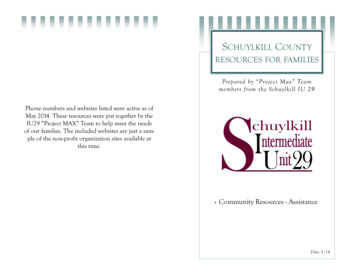
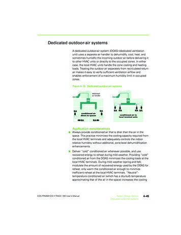
Hardware OverviewFigure 1 AP-574 Front View (with Aesthetic Cover)The antenna connectors of AP-574 are covered by an aesthetic cover. The aesthetic cover can be removedwhen necessary.Figure 2 AP-574 Rear View (with Aesthetic Cover)System LEDGrounding Point2E0E1USB Console Port& Reset ButtonAruba 570 Series Outdoor Access Points Installation Guide
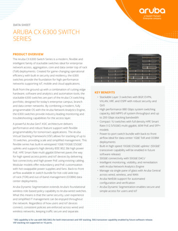
Figure 3 AP-575 Front ViewFigure 4 AP-575 Rear ViewGrounding PointE0E1USB Console Port& Reset ButtonAruba 570 Series Outdoor Access Points Installation GuideSystem LED3
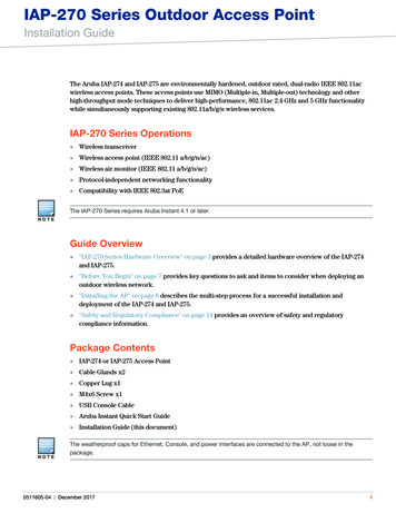
Figure 5 AP-577 Front ViewFigure 6 AP-577 Rear ViewSystem LEDGrounding Point4E0E1USB Console Port& Reset ButtonAruba 570 Series Outdoor Access Points Installation Guide
External Antenna ConnectorsThe AP-574 access point is equipped with six external antenna connectors. The connectors are labeled 2G0, 2G1,5G0, 5G1, 5G2, and 5G3.!External antennas for this device must be installed by an Aruba Certified Mobility Professional (ACMP) or otherAruba-certified technician, using manufacturer-approved antennas only.The Equivalent Isotropically Radiated Power (EIRP) levels for all external antenna devices must not exceed theregulatory limit set by the host country/domain.Installers are required to record the antenna gain for this device in the system management software.Les antennes externes pour cet appareil doivent être installées par un professionnel de la mobilité certifié Aruba(ACMP) ou un autre technicien certifié Aruba, en utilisant uniquement des antennes approuvées par le fabricant.Les niveaux équivalents de puissance à rayonnement isotrope (EIRP) pour tous les périphériques d'antenneexterne ne doivent pas dépasser la limite réglementaire définie par le pays hôte / domaine.Les installateurs doivent enregistrer le gain d'antenne pour cet appareil dans le logiciel de gestion du système.Figure 7 AP-574 Bottom View (without Aesthetic Cover)LEDThe 570 Series access point is equipped with one LED that indicates the system status of the access point.Aruba 570 Series Outdoor Access Points Installation Guide5
Table 1 570 Series LED Meanings during Boot UpLEDColor/StateMeaningSystem LEDOffNo power to APRedInitial power-upGreen - FlashingAP booting, not readyGreen - SteadyAP ready and Gigabit Ethernet connected. The LED turns off after1200 secondsGreen - Yellow, 6 secondsperiodAP ready and 10/100Mbps Ethernet link established. The LEDturns off after 1200 secondsTable 2 570 Series LED Meanings during OperationLEDColor/StateMeaningSystem LEDSolid RedGeneral fault - Immediate attention requiredOne blink off every 3secondsRadio 0 fault (5 GHz)Two quick blink off 0.5seconds apart cycled every3 secondsRadio 1 fault (2.4GHz)Ethernet PortsThe 570 Series access points are equipped with two Ethernet ports (E0 and E1): E0 port: 100/1000/2500Base-T auto-sensing MDI/MDX wired RJ45 network connectivity port E1 port: 100/1000Base-T auto-sensing MDI/MDX wired RJ45 network connectivity portPowerBoth E0 and E1 ports support PoE-in, allowing the AP to draw power from an 802.3at/802.3bt PoE power source.When the AP is powered by both E0 and E1 ports simultaneously, the AP can be configured by managementsoftware to source PoE power from either port, or to combine power from both ports.The 570 Series access points support the Intelligent Power Monitoring (IPM) feature, to report AP powerconsumption and enable intelligent management of power-save capabilities.Table 3 lists operational restrictions when the AP is powered by different power options.Table 3 Power Options and Operational Restrictions6Power SourceIPMRestrictions1 x 802.3bt PoEn/aNo restrictions, all capabilities available.2 x 802.3at PoEn/aNo restrictions, all capabilities available.1 x 802.3at PoEenabledAP starts up in unrestricted mode, but may dynamicallyapply restrictions depending on the PoE budget and actualpower.1 x 802.3at PoEdisabledSecond (other) Ethernet port disabled.1 x 802.3af PoEn/aAP does not start up, red system LED.Aruba 570 Series Outdoor Access Points Installation Guide
Grounding PointAlways remember to protect the access point by installing grounding lines. The ground connection must becomplete before connecting power to the access point enclosure.USB Type-C Console PortUse the included USB Type-C console cable to connect the access point to a laptop or a serial terminal for directmanagement.You need a proper 8mm allen or hex key to open the cover of the USB Console port.Reset ButtonThe reset button can be used to reset the access point to factory default settings or turn off/on the LED display.There are two ways to reset the access point to factory default settings:Reset the AP during normal operationPress and hold down the reset button using a small, narrow object such as a paper clip for more than 10seconds during normal operation.Reset the AP while powering up1. Press and hold down the reset button using a small, narrow object such as a paper clip while the access pointis not powered on via PoE.2. Connect the power supply (PoE) to the access point while the reset button is being held down.3. Release the reset button on the access point after 15 seconds.To turn off/on the LED display, press and release the reset button using a small, narrow object, such as apaperclip for less than 10 seconds during normal operation of the access point.Before You BeginRefer to the sections below before beginning the installation process.!FCC Statement: Improper termination of access points installed in the United States configured to non-USmodel controllers will be in violation of the FCC grant of equipment authorization. Any such willful orintentional violation may result in a requirement by the FCC for immediate termination of operation and maybe subject to forfeiture (47 CFR 1.80).Pre-Installation ChecklistBefore installing your 570 Series access point, be sure that you have the following: Cat5E or better UTP cable with network access A compatible PoE injector with power cordOne of the following network services: Aruba Discovery Protocol (ADP) DNS server with an “A” record DHCP Server with vendor specific optionsAruba, in compliance with governmental requirements, has designed the 570 Series access points so that onlyauthorized network administrators can change configuration settings. For more information about APconfiguration, refer to the AP Software Quick Start Guide.Aruba 570 Series Outdoor Access Points Installation Guide7
!Access points are radio transmission devices and as such are subject to governmental regulation. Networkadministrators responsible for the configuration and operation of access points must comply with localbroadcast regulations. Specifically, access points must use channel assignments appropriate to the location inwhich the access point will be used.Outdoor Planning and Deployment ConsiderationsPrior to deploying an outdoor wireless network, the environment must be evaluated to plan for a successfulWLAN deployment. Successfully evaluating the environment enables the proper selection of routers andantennas and assists in the determination of their placement for optimal RF coverage. This process is consideredWLAN or RF planning and Aruba’s system engineers can assist in the outdoor planning process.The rules for the 5600-5650 MHz band vary by region.Identifying Specific Installation LocationsUse the access point placement map generated by Aruba RF Plan software application to determine the properinstallation location(s). Each location should be as close as possible to the center of the intended coverage areaand should be free from obstructions or obvious sources of interference. These RF absorbers/reflectors/interference sources will impact RF propagation and should be accounted for during the planning phase andadjusted for in RF plan.!Use of this equipment adjacent to or stacked with other equipment should be avoided because it could result inimproper operation. If such use is necessary, this equipment and the other equipment should be observed toverify that they are operating normally.Identifying Known RF Absorbers/Reflectors/Interference SourcesIdentifying known RF absorbers, reflectors, and interference sources while in the field during the installationphase is critical. Make sure that these sources are taken into consideration when you attach an access point to itsfixed location.RF absorbers include:Cement/concrete—Old concrete has high levels of water dissipation, which dries out the concrete, allowingfor potential RF propagation. New concrete has high levels of water concentration in the concrete, blockingRF signals. Natural Items—Fish tanks, water fountains, ponds, and trees Brick RF reflectors include: Metal Objects—Metal pans between floors, rebar, fire doors, air conditioning/heating ducts, mesh windows,blinds, chain link fences (depending on aperture size), refrigerators, racks, shelves, and filing cabinets. Do not place an access point between two air conditioning/heating ducts. Make sure that access points areplaced below ducts to avoid RF disturbances.RF interference sources include: Microwave ovens and other 2.4 or 5 GHz objects (such as cordless phones) Cordless headset such as those used in call centers or lunch roomsAccess Point InstallationService to all Aruba products should be performed by trained service personnel only.8Aruba 570 Series Outdoor Access Points Installation Guide
Using Mount KitsThe 570 Series access point can be installed on a wall or attached to a pole by using mount kits:Table 4 Applicable Mount Kits for 570 Series Access PointPart NumberDescriptionJW052AAP-270-MNT-V1 long mount kit for wall and vertical pole mounting, 300 mm fromvertical mounting asset.JW053AAP-270-MNT-V2 short mount kit for wall and vertical pole mounting, 75 mm fromvertical mounting asset.JW054AAP-270-MNT-H1 mount kit for hanging from inclined or horizontal structure.JW055AAP-270-MNT-H2 flush mount kit for wall and ceiling mounting.The 570 Series access point does not ship with any mount kits. These mount kits are available as accessoriesand must be ordered separately.For installation instructions on AP-270-MNT-V1, AP-270-MNT-V2, AP-270-MNT-H1 and AP-270-MNT-H2 mountkit, please refer to the AP-270-MNT-V1 Installation Guide, AP-270-MNT-V2 Installation Guide, AP-270-MNT-H1Installation Guide and AP-270-MNT-H2 Installation Guide respectively.Mounting instructions for the antennas for the AP-574 access points are provided with the antennas. Themounting must be consistent with the instructions provided to ensure compliance with US and Canadianregulatory requirements when used outdoors.!This 570 Series access point is intended for installation in a RESTRICTED ACCESS LOCATION attached to a poleor installed on a wall. Installers should disconnect power before working with or near the access point.Grounding the Access PointThe grounding must be completed before powering up the access point. The grounding wire should be #8 AWG.1. Peel the cover of one end of the grounding wire and place the bare grounding wire into the grounding lug(included in the package), and press firmly with the crimping pliers.2. Fasten the grounding lug to the grounding hole on the access point with the screw (included in the package).Connecting the Ethernet CableTo connect the Ethernet cable to the access point, perform the following steps using the Ethernet cable glandsthat ships with your access point.!Failure to use the included Ethernet cable glands can lead to connectivity and POE issues.The cable is not included and must be purchased separately. Purchase a suitable UV-resistant, outdoor rated,CAT 5E or better RJ45 cable for use with the access point.Aruba 570 Series Outdoor Access Points Installation Guide9
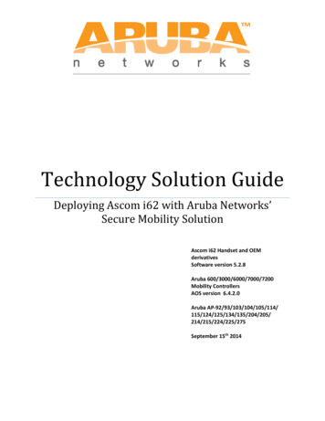
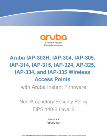
Figure 8 Installing the Ethernet Cable GlandSplit GrommetClipSealing NutGland Body1. Remove the dust cap from the Ethernet port2. Slide the sealing nut, clip, split grommet and gland body over the cable.3. Insert the RJ45 connector to the Ethernet port.4. Screw the gland body onto the Ethernet port.5. Combine the two split parts of the grommet over the cable, and move it towards the gland body until itlocates at the recess of the gland body.6. Move the clip towards the gland body, passing over the grommet, until the wavy end of the clip properly fitsinto the wavy end of the gland body.7. Screw the sealing nut onto the gland body.Two grommets are provided in the package for use with the Ethernet cables. One is applicable for cables with4-6 mm diameter, and another is applicable for cables with 6-10 mm diameter.SoftwareFor instructions on choosing operating modes and initial software configuration, refer to the AP Software QuickStart Guide.!Aruba access points are classified as radio transmission devices, and are subject to government regulations ofthe host country. The network administrator(s) is/are responsible for ensuring that configuration and operationof this equipment is in compliance with their country’s regulations. For a complete list of approved channels inyour country, refer to the Aruba Downloadable Regulatory Table at .htmVerifying Post-Installation ConnectivityThe integrated LEDs on the access point can be used to verify that the access point is receiving power andinitializing successfully (see Table 1 and Table 2). Refer to the AP Software Quick Start Guide for further detailson verifying post-installation network connectivity.Electrical and Environmental SpecificationsElectrical Ethernet E0: 100/1000/2500Base-T auto-sensing Ethernet RJ-45 Interfaces E1: 100/1000Base-T auto-sensing Ethernet RJ-45 Interfaces Power over Ethernet (IEEE 802.3at and 802.3bt compliant)Environmental 10OperatingAruba 570 Series Outdoor Access Points Installation Guide
Temperature: -40ºC to 65ºC (-40ºF to 149ºF)Storage Temperature: -40ºC to 70ºC (-40ºF to 158ºF) Humidity: 5% to 93% non-condensingFor additional specifications on this product, please refer to the data sheet at www.arubanetworks.com.Regulatory Model NumberFor the purpose of regulatory compliance certifications and identification, this product has been assigned aunique regulatory model number (RMN). The regulatory model number can be found on the product nameplatelabel, along with all required approval markings and information. When requesting compliance information forthis product, always refer to this regulatory model number. The regulatory model number RMN is not themarketing name or model number of the product.The following regulatory model numbers apply to the 570 Series: AP-574 RMN: APEX0574 AP-575 RMN: APEX0575 AP-577 RMN: APEX0577Safety and Regulatory Compliance!RF Radiation Exposure Statement: This equipment complies with RF radiation exposure limits. Thisequipment should be installed and operated with a minimum distance of 13.78 inches (35cm) between theradiator and your body for 2.4 GHz and 5 GHz operations. This transmitter must not be co-located or operatingin conjunction with any other antenna or transmitter.!Déclaration de la concernant l’exposition aux rayonnements à fréquence radioélectrique (FR): Cetappareil est conforme aux limites d’exposition aux rayonnements FR établies par la FCC. Il doit être installé etutilisé à une distance minimale de 35 cm (13,78 pouces) entre le radiateur et votre corps, qu’il opère sur labande 2,4 GHz ou 5 GHz. Cet émetteur ne doit pas être installé ou utilisé à proximité immédiate d’une autreantenne ni d’un autre transmetteur.!The device could automatically discontinue transmission in case of absence of information to transmit, oroperational failure. Note that this is not intended to prohibit transmission of control or signaling informationor the use of repetitive codes where required by the technology.!Changes or modifications to this unit not expressly approved by the party responsible for compliance couldvoid the user’s authority to operate this equipment.!Toute modification effectuée sur cet équipement sans l'autorisation expresse de la partie responsable de laconformité est susceptible d'annuler son droit d'utilisation.United StatesThis equipment has been tested and found to comply with the limits for a Class B digital device, pursuant to Part15 of the FCC Rules. These limits are designed to provide reasonable protection against harmful interference in aresidential installation. This equipment generates, uses and can radiate radio frequency energy and, if notinstalled and used in accordance with the manufacturer’s instructions, may cause harmful interference to radiocommunications. However, there is no guarantee that interference will not occur in a particular installation. Ifthis equipment does cause harmful interference to radio or television reception, which can be determined byturning the equipment off and on, the user is encouraged to try to correct the interference by one or more of thefollowing measures:Aruba 570 Series Outdoor Access Points Installation Guide11
Reorient or relocate the receiving antenna.Increase the separation between the equipment and receiver. Connect the equipment to an outlet on a circuit different from that to which the receiver is connected. Consult the dealer or an experienced radio or TV technician for help.Improper termination of access points installed in the United States configured to a non-US model controller is aviolation of the FCC grant of equipment authorization. Any such willful or intentional violation may result in arequirement by the FCC for immediate termination of operation and may be subject to forfeiture (47 CFR 1.80). Industry CanadaThis Class B digital apparatus meets all of the requirements of the Canadian Interference-Causing EquipmentRegulations.In accordance with Industry Canada regulations, this radio transmitter and receiver may only be used with anantenna, the maximum type and gain of which must be approved by Industry Canada. To reduce potential radiointerference, the type of antenna and its gain shall be chosen so that the equivalent isotropic radiated power(EIRP) does not exceed the values necessary for effective communication.This device complies with Industry Canada's license-exempt RSS regulations. Operation of this device is subjectto the following two conditions: (1) this device may not cause interference, and (2) this device must accept anyinterference, including interference that may cause undesired operation.When operated in 5.15 to 5.25 GHz frequency range, this device is restricted to indoor use to reduce thepotential for harmful interference with co-channel Mobile Satellite Systems.This radio transmitter model APEX0574 has been approved by Industry Canada to operate with the antennatypes listed in the online ordering guide (link provided below) with the maximum permissible gain indicated.Antenna types not included in this list, having a greater gain than the maximum gain indicated for that type, arestrictly prohibited for use with this device.https://www.arubanetworks.com/assets/og/OG AP-570Series.pdfDéclaration d’Industrie CanadaCe périphérique est conforme aux règlements RSS exempts de licence d’Industrie Canada. L’utilisation de cepériphérique est soumise aux deux conditions suivantes : (1) ce périphérique ne doit pas provoquerd’interférences, et (2) ce périphérique doit accepter toute interférence, y compris les interférences susceptiblesde provoquer un dysfonctionnement.En cas d'utilisation dans la plage de fréquences de 5,15 à 5,25 GHz, cet appareil doit uniquement être utilisé enintérieur afin de réduire les risques d'interférence avec les systèmes satellites mobiles partageant le mêmecanal.Ce modèle d'émetteur radio APEX0574 a été approuvé par Industrie Canada pour fonctionner avec les typesd'antenne énumérés dans le guide de commande en ligne (lien ci-dessous) avec le gain maximal admissibleindiqué. Les types d'antennes non inclus dans cette liste, ayant un gain supérieur au gain maximal indiqué pource type, sont strictement interdits pour une utilisation avec cet G AP-570Series.pdfEuropean Union Regulatory ConformanceThe Declaration of Conformity made under Radio Equipment Directive 2014/53/EU is available for viewing at:www.hpe.com/eu/certificates. Select the document that corresponds to your device’s model number as it isindicated on the product label.This radio transmitter model has been approved to operate with the antenna types listed in the online orderingguide (link provided below) with the maximum permissible gain indicated. Antenna types not included in this list,having a greater gain than the maximum gain indicated for the type, are strictly prohibited for use with thisdevice. Compliance is only assured if the Aruba approved accessories as listed in the ordering guide are used.http://www.arubanetworks.com/assets/og/OG AP-570Series.pdfWireless Channel Restrictions5150-5350MHz band is limited to indoor only in the following countries; Austria (AT), Belgium (BE), Bulgaria (BG),Croatia (HR), Cyprus (CY), Czech Republic (CZ), Denmark (DK), Estonia (EE), Finland (FI), France (FR), Germany (DE),Greece (GR), Hungary (HU), Iceland (IS), Ireland (IE), Italy (IT), Latvia (LV), Liechtenstein (LI), Lithuania (LT),Luxembourg (LU), Malta (MT), Netherlands (NL), Norway (NO), Poland (PL), Portugal (PT), Romania (RO), Slovakia12Aruba 570 Series Outdoor Access Points Installation Guide
(SK), Slovenia (SL), Spain (ES), Sweden (SE), Switzerland (CH), Turkey (TR), United Kingdom (UK).RadioFrequency Range MHzMax EIRPBLE/Zigbee2402-24809 dBm2412-247220 dBm5150-525023 dBm5250-535023 dBm5470-572530 dBm5725-585014 dBmWi-Fi!Lower power radio LAN product operating in 2.4 GHz and 5 GHz bands. Please refer to the ArubaOS User Guide/Instant User Guide for details on restrictions.Medical1. Equipment not suitable for use in the presence of flammable mixtures.2. Connect to only IEC 60950-1 or IEC 60601-1 certified products and power sources. The end user isresponsible for the resulting medical system complies with the requirements of IEC 60601-1.3. Wipe with a dry cloth, no additional maintenance required.4. No serviceable parts, the unit must be sent back to the manufacturer for repair.5. No modifications are allowed without Aruba ��指依電信法規定作業之無線電通信。 ��干擾。1. 應避免影響附近雷達系統之操作。2. �對點系統3. 電磁波暴露量 MPE 標準值 1 mW/cm2, 送測產品實測值為 : 0.97mW/cm2BrazilEste equipamento não tem direito à proteção contra interferência prejudicial e não pode causar interferênciaem sistemas devidamente autorizados.JapanMéxicoLa operación de este equipo está sujeta a las siguientes dos condiciones: (1) es posible que este equipo odispositivo no cause interferencia perjudicial y (2) este equipo o dispositivo debeaceptar cualquier interferencia,incluyendo la que pueda causar su operación no deseada.Aruba 570 Series Outdoor Access Points Installation Guide13
Нормативные требования Евразийского Экономического СоюзаHPE Russia: ООО "Хьюлетт Паккард Энтерпрайз" Российская Федерация, 125171, г.Москва, Ленинградское шоссе, 16А, стр.3, Телефон: 7 499 403 4248 Факс: 7 499 4034677'HPE Kazakhstan': TOO «Хьюлетт-Паккард (К)», Республика Казахстан, 050040, г.Алматы, Бостандыкский район, проспект Аль-Фараби, 77/7, Телефон/факс: 7 727355 35 50KazakhstanЖШС "Хьюлетт Паккард Энтерпрайз" Ресей Федерациясы, 125171, Мәскеу, Ленинград тас жолы, 16A блок3, Телефон: 7 499 403 4248 Факс: 7 499 403 4677ЖШС «Хьюлетт-Паккард (К)», Қазақстан Республикасы, 050040, Алматы к., Бостандык ауданы, Әл-Фарабидаңғ ылы, 77/7, Телефон/факс: 7 (727) 355 35 50UkraineHereby, Hewlett Packard Enterprise Company declares that the radio equipment type [The Regulatory ModelNumber [RMN] for this device can be found in the Regulatory Model Number section of this document] is incompliance with Ukrainian Technical Regulation on Radio Equipment, approved by resolution of the CABINET OFMINISTERS OF UKRAINE dated May 24, 2017, No. 355. The full text of the UA declaration of conformity isavailable at the following internet address: es.htmlХ’ЮЛЕТТ ПАКАРД ЕНТЕРПРАЗ, 6280 АМЕРИКА ЦЕНТР Д-Р, САН-ХОСЕ, КАЛІФОРНІЯ 95002, СШАOmanAP-574OMAN - TRAD192690R/9790/20AP-575OMAN - TRAD192690R/9789/20AP-577OMAN - TRAD192690R/9788/2014Aruba 570 Series Outdoor Access Points Installation Guide
PhilippinesAP-574Type-ApprovalNo. ESD-2022590CAP-575Type-ApprovalNo. ESD-2022591CAP-577Type-ApprovalNo. ESD-2022592CSingaporeDB100427Aruba 570 Series Outdoor Access Points Installation Guide15
Contact ArubaMain Sitehttps://www.arubanetworks.comSupport Sitehttps://asp.arubanetworks.comAirheads Social Forums and Knowledge Basehttps://community.arubanetworks.com/North America Telephone1-800-943-45261-408-754-1200International vices/contact-support/Software Licensing ife ervices/end-of-life/Security Incident Response Team e/security-bulletins/Email: aruba-sirt@hpe.comCopyright Copyright 2021 Hewlett Packard Enterprise Development LPOpen Source CodeThis product includes code licensed under the GNU General PublicLicense, the GNU Lesser General Public License, and/orcertain other open source licenses.A complete machine-readable copy of the source code corresponding to such code is available upon request. This offer is validto anyone in receipt of this information and shall expire three years following the date of the final distribution of this productversion by Hewlett Packard Enterprise Company.To obtain such source code, send a check or money order in the amount of US 10.00 to:Hewlett Packard Enterprise CompanyAttn: General Counsel6280 America Center DriveSan Jose, CA 94089USAWarrantyThis hardware product is protected by an Aruba warranty. For more details, visit www.hpe.com/us/en/support.html16Aruba 570 Series Outdoor Access Points Installation Guide
vertical mounting asset. JW053A AP-270-MNT-V2 short mount kit for wall and vertical pole mounting, 75 mm from vertical mounting asset. JW054A AP-270-MNT-H1 mount kit for hanging from inclined or horizontal structure. JW055A AP-270-MNT-H2 flush mount kit for wall and ceiling mounting. The 570 Series access point does not ship with any mount kits.