Transcription
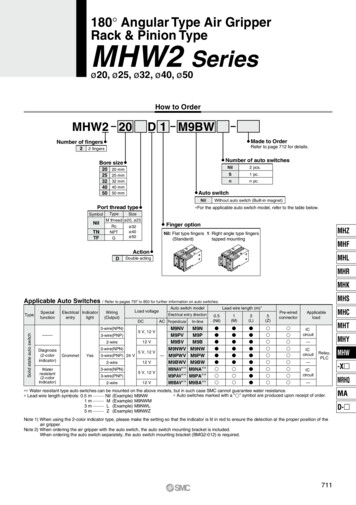
180 Angular Type Air GripperRack & Pinion TypeMHW2 Seriesø20, ø25, ø32, ø40, ø50How to OrderMHW2 20D 1 M9BWMade to OrderNumber of fingers2Refer to page 712 for details.2 fingersNumber of auto switchesBore size202532405020 mm25 mm32 mm40 mm50 mmNilNilTNTF2 pcs.S1 pc.nn pc.Auto switchPort thread typeSymbolNilTypeSizeM thread ø20, ø25Rcø32ø40NPTø50GWithout auto switch (Built-in magnet) For the applicable auto switch model, refer to the table below.Finger optionMHZNil: Flat type fingers 1: Right angle type fingers(Standard)tapped mountingMHFActionDMHLDouble actingMHRMHKMHSApplicable Auto Switches / Refer to pages 797 to 850 for further information on auto switches.TypeSpecialfunctionElectrical IndicatorentrylightWiring(Output)Solid state auto e(PNP)2-wireLoad voltageDCElectrical entry directionAC PerpendicularM9NVM9PV12 VM9BVM9NWV5 V, 12 V24 V— M9PWV12 VM9BWVM9NAV 5 V, 12 VM9PAV 12 VM9BAV 5 V, 12 VLead wire length (m) Auto switch 9BWM9NA M9PA M9BA Pre-wiredconnector ay,PLCMHW-X ICcircuitMRHQ— Water resistant type auto switches can be mounted on the above models, but in such case SMC cannot guarantee water resistance. Auto switches marked with a “ ” symbol are produced upon receipt of order. Lead wire length symbols: 0.5 m ········· Nil (Example) M9NW1 m ········· M (Example) M9NWM3 m ········· L (Example) M9NWL5 m ········· Z (Example) M9NWZNote 1) When using the 2-color indicator type, please make the setting so that the indicator is lit in red to ensure the detection at the proper position of theair gripper.Note 2) When ordering the air gripper with the auto switch, the auto switch mounting bracket is included.When ordering the auto switch separately, the auto switch mounting bracket (BMG2-012) is required.711MAD-
MHW2 SeriesSpecificationsAirFluid0.15 to 0.7 MPaOperating pressure–10 to 60 CAmbient and fluid temperature 0.2 mmRepeatabilityø20, 25: 60 c.p.m.ø32 to 50: 30 c.p.m.Max. operating frequencyLubricationNot requiredActionDouble actingAuto switch (Option) Note)Solid state auto switch (3-wire, 2-wire)Note) Refer to pages 797 to 850 for further information on auto switches.SymbolModelDouble acting: External gripModelEffectivegripping force(N·m)200.30 5 250.73 6 de to Order(Refer to pages 725 to 748 for the ations/DescriptionHeat resistanceFluororubber sealWithout magnetEPDM for seals, Fluorine greaseFluorine greaseGrease for food processing machines, Fluorine greaseGrease for food processing machinesOpening angle(Both sides)Bore 1Opening Closing180 5 403.70 5 508.27 4 Weight (2)(g)3003205105409109502140227051005350Note 1) At the pressure of 0.5 MPaNote 2) Except auto switch Refer to “How to Select the Applicable Model” on page 700 Refer to pages 700 and 701 for the details on effective holding force and allowableoverhanging distance.PrecautionsBe sure to read this before handling the products.Refer to back page 50 for Safety Instructions and pages 366 to 374 for Air Gripper and Auto Switch Precautions.MountingMHWWarningWhen using right angle finger tap mountingtype, monitor the interference of the bolt withthe speed controller.Tighten thebolt fromthis sideFingerBolt interferes with speed controller712
180 Angular Type Air GripperRack & Pinion TypeMHW2 SeriesConstructionre@1@0!2!6!3!5 uClosed conditionot !8 i !9!4yqew!0@2!7!1Open conditionMHZMHFMHLMHRMHKMHSMHCComponent um alloyHard anodizedPistonAluminum alloyHard anodizedCarbon steelHeat treatedPinion gearSeal coverBrassBumperUrethane rubberFinger (A)Carbon steelNitridingFinger (B)Carbon steelNitridingRubber magnetSynthetic rubberRackCarbon steelNitridingNo.DescriptionMaterialNoteø20, 25: Resin10Cap11121314151617Piston boltStainless steelBall bearingCarbon steelKeyCarbon steelHexagon socket head boltHexagon socket cap screwø32 to 50: Aluminum alloy Hard anodizedDescriptionFinger assemblyFinger A assemblyFinger C assemblyFinger B assemblyMHWCarbon steelZinc chromated-X Carbon steelZinc chromatedType C retaining ringCarbon steelPhosphate coatedType C retaining ringCarbon steelPhosphate ain MHW2- - A5002-1MHW2- HW2- A5007 Please order 1 piece finger assembly per one unit.Replacement part/grease pack part no. :ø20, ø25, ø32 : GR-S-010(10 g)ø40, 50 : GR-S-020(20 g)MHYSchield typeReplacement PartsSeal kitPiston assemblyMHTyu!3!4!5u!3!5713MRHQMAD-
MHW2 SeriesDimensionsMHW2-20D20Flat finger type (Standard)2 x M5 x 0.8 thread depth 7(Mounting thread)17604 x M5 x 0.8 thread depth 10 (Mounting thread)Bottom through hole dia. 4.2 (Mounting hole)45352 x M5 x 0.8 thread depth 10(Mounting thread)22636723182723ø21H9 0.052depth 3012 0.2 0.11626364 x M4 x 0.7 thread depth 5(Thread for mounting attachment)Auto Switch MountingGroove Dimensions5412413018M5 x 0.8(Finger closing port)9M5 x 0.8(Finger opening port)6.454206MHW2-20D114284171454 x M4 x 0.7 through(Thread for mounting attachment)101531Right angle finger type1116
180 Angular Type Air GripperRack & Pinion TypeMHW2 SeriesDimensionsMHW2-25D24Flat finger type (Standard)202 x M6 x 1 thread depth 10(Mounting thread)4 x M6 x 1 thread depth 12 (Mounting thread)Bottom through hole dia. 5.1 (Mounting hole)2 x M6 x 1 thread depth 12(Mounting thread)2827243440273051456917 0.2 0.14 x M5 x 0.8 thread depth 6(Thread for mounting attachment)MHFMHLAuto Switch MountingGroove DimensionsMHR164530.320M5 x 0.8(Finger closing port)MHZø26H9 0.0520 depth 33040214.5MHKMHSM5 x 0.8(Finger opening port)6.45MHW2-25D1Right angle finger typeMHC5104.523MHT5.5MHYMHW-X MRHQMA1861237D- 151630454 x M5 x 0.8 through(Thread for mounting attachment)21715
MHW2 SeriesDimensionsMHW2-32D24Flat finger type (Standard)212 x M6 x 1 thread depth 10(Mounting thread)83.561.54 x M6 x 1 thread depth 12 (Mounting thread)Bottom through hole dia. 5.1 (Mounting hole)472 x M6 x 1 thread depth 12(Mounting thread)245589323042294 x M6 x 1 thread depth 7(Thread for mounting attachment)23 0.2 0.127ø34H9 0.062depth 4030Rc 1/8 (G1/8, NPT1/8)(Finger closing port)451120205132.9Auto Switch MountingGroove Dimensions13Rc 1/8 (G1/8, NPT1/8)(Finger opening port)11MHW2-32D118347165171421446.45Right angle finger type4 x M6 x 1 through(Thread for mounting attachment)20275.5525
180 Angular Type Air GripperRack & Pinion TypeMHW2 SeriesDimensionsMHW2-40D30Flat finger type (Standard)27.52 x M8 x 1.25 thread depth 15(Mounting thread)104.54 x M8 x 1.25 thread depth 16 (Mounting thread)Bottom through hole dia. 6.8 (Mounting hole)75.52 x M8 x 1.25 thread depth 15(Mounting thread)56.5360801242405437.5304 x M8 x 1.25 thread depth 9(Thread for mounting attachment) 0.3 0.136MHZø42H9 0.062depth 4036Rc 1/8 (G1/8, NPT1/8)(Finger closing port)MHF56MHLMHR2028MHK1014Rc 1/8 (G1/8 ,NPT1/8)(Finger opening port)MHS1033.5MHC56745Auto Switch MountingGroove Dimensions6.45MHW2-40D1Right angle finger typeMHT6MHYMHW-X MRHQMA30446710242160D- 4 x M8 x 1.25 through2636(Thread for mounting attachment)717
MHW2 SeriesDimensionsMHW2-50D40Flat finger type (Standard)2 x M10 x 1.5 thread depth 20(Mounting thread)36136964 x M10 x 1.5 thread depth 20 (Mounting thread)Bottom through hole dia. 8.5 (Mounting hole)692 x M10 x 1.5 thread depth 20(Mounting thread)8011270 0.444 0.14052ø52H9 0.0740 depth 566Rc 1/4 (G1/4, NPT1/4)(Finger closing port)Auto Switch MountingGroove Dimensions13Rc 1/4 (G1/4, NPT1/4)(Finger opening port)6.4522 1613303858.6854 x M10 x 1.5 through(Thread for mounting attachment)MHW2-50D137588571812302478Right angle finger type4 x M10 x 1.5 through(Thread for mounting attachment)395265417585648
MHY2/MHW2 SeriesAuto Switch Installation Examplesand Mounting PositionsVarious auto switch applications are possible through different combinations of auto switch quantities and detecting positions.Detection when Gripping Exterior of WorkpieceDetection example1. Confirmation of the fingers in reset positionPosition of fingersfully opened2. Confirmation of work heldPosition when gripping a workpiecePosition to be detectedOperation of auto switchAuto Switch turned ON when fingers return.(Light ON)Auto Switch turned ON when gripping a workpiece.(Light ON)Step 1) Position fingers for gripping a workpiece.Step 1) Completelyopen the fingers.How to determineauto switchinstallation positionMHZAt no pressure or low pressure,connect the auto switch to apower supply, and follow thedirections.Step 2) Insert the auto switch into the switch groove in thedirection shown in the drawing.Step 2) Insert the auto switch into the switch groove inthe direction shown in the drawing.MHFMHLMHRMHKStep 3) Slide the auto switch in the direction of thearrow until the indicator light illuminates.Step 3) Slide the auto switch in the direction of thearrow until the indicator light illuminates. Move theswitch an additional 0.3 to 0.5 mm in the direction of thearrow and fasten it.MHSMHCMHTStep 4) Slide the auto switch further in the direction ofthe arrow until the indicator light goes out.MHYPosition where light turns ONMHW-X 0.3 to 0.5 mmStep 5) Move the auto switch in the opposite directionand fasten it at a position 0.3 to 0.5 mm beyond theposition where the indicator light illuminates.MRHQPosition to be securedMAD- Position wherelight turns ONPosition tobe secured0.3 to 0.5 mm719
MHY2 SeriesAuto Switch MountingProtrusion of Auto Switch from Edge of BodyTo set the auto switch, insert the auto switch into the installationgroove of the gripper from the direction indicated in the followingdrawing. After setting the position, tighten the attached autoswitch mounting set screw with a flat head watchmaker’sscrewdriver.The projection of an auto switch from the edge of the body isshown in the table below. Use the table as a guideline formounting.Note) 2-color indicator type and perpendicular entry type protrude in thedirection of the lead wire entry.Flat headwatchmaker’s screwdriverLø5 to ø6When auto switch D-M9 is usedAuto switch mounting screwM2.5 x 4 LAuto switchLNote) Use a watchmaker’s screwdriver with a grip diameter of 5 to 6 mmto tighten the auto switch mounting screw.The tightening torque should be about 0.05 to 0.15 N·m. Refer to the page 804 for the details on “Auto Switches Connectionand Example”.When auto switch D-M9 V is usedMax. Protrusion of Auto Switchfrom Edge of Body (L)Auto switchmodelAuto Switch HysteresisAuto switches have hysteresis similar to micro switches. Use thetable below as a guide when adjusting auto switch positions, uto switch reset position (OFF)MHY2-20DtereHysMHY2-25DsisHysteresisAuto switch operating position (ON)Auto switch operating position (ON)Auto switch reset position (OFF)D-M9 (V)D-M9 W(V)/M9A(V)MHY2 Finger fully closed-10DFinger fully open2 MHY2 Finger fully closed-16DFinger fully open2 MHY2 Finger fully closed-20DFinger fully open2 MHY2 Finger fully closed-25DFinger fully open1 7204 3 3 2 In-line(mm)ProtrusionPerpendicular In-linePerpendicularD-M9 D-M9 VD-M9 A D-M9 AVD-M9 W D-M9 Closed——1—
180 Angular Type Air GripperAuto Switch MountingMHW2 SeriesHandling of Mounting Brackets(1) Insert the auto switch bracket into the installation groove ofthe gripper as shown below and roughly set it.(2) Insert the auto switch into the auto switch bracket installationgroove.(3) After confirming the detecting position, tighten the set screws(M2.5) attached to the auto switch and set it.(4) Be sure to change the detecting position in the state of (2).When auto switch is set on mounting side as shown below, allowat least 2 mm run off space on mounting late since the autoswitch is protruded from the gripper edge.Run off space2 mm or moreAuto switch mounting bracketAuto Switch Mounting Bracket: Part No.Auto switch part no.D-M9 (V)/M9 W(V)/M9 A(V)Auto switch mounting bracket part no.BMG2-012Note) Use a screwdriver with a grip diameter of 5 to 6 mm to tighten theset screws (M2.5). The tightening torque should be 0.5 to 1 N m. Asa rule, it should be turned about 90 beyond the point at whichtightening can be felt.Auto Switch HysteresisAuto switches have hysteresis similar to micro switches. Use thetable below as a guide when adjusting auto switch positions, etc.Protrusion of Auto Switch from Edge of BodyThe maximum protrusion of an auto switch (when fingers are fullyclosed) from the edge of the body is shown in the table below.Use the table as a guideline for mounting.When auto switchesD-M9 /M9 W/Y59 ABD-M9 AD-Y7 , Y7 Ware usedLMHZWhen auto switchesD-M9 V/M9 WV/Y69 ABD-M9 AVD-Y7 V, Y7 WVare usedMHFMHLLMHRMHKMHSMax. Protrusion of Auto Switchfrom Edge of Body (L)Air grippermodelMHW2-20DHysteresisAuto switch operating position (ON)MHW2-25DAuto switch reset position (OFF)MHW2-32DAuto switchmodelAir grippermodelD-Y59 /Y69 D-Y7P(V)/Y7 W(V)MHW2-20DMHW2-25DMHW2-32DMHW2-40DMHW2-50D4 4 2 2 2 Auto switch Max. hysteresis (Max. value)D-M9 (V)modelAir 0DD-M9 W(V)D-M9 A(V)4 4 2 2 2 (mm)Auto switchProtrusion (mm)Finger model In-line electrical entry type Perpendicular electrial entry typepositionD-Y59 /Y7P/Y7 WD-Y69 /Y7PV/Y7 —1——MHW-X MRHQAuto switchProtrusion (mm)Finger model In-line electrical entry type Perpendicular electrial entry typepositionD-M9 /M9 W M9 A D-M9 V/M9 WV M9 �—MHTMHY(mm)Air grippermodelMHC—7—7—4—3—1721MAD-
MHY2/MHW2 SeriesSpecific Product Precautions 1Be sure to read this before handling the products.Mounting Air Grippers/MHY2 SeriesPossible to mount from 3 directions.Axial Mounting(Body Tapped)Lateral mounting(Body Tapped, Body through-hole)Vertical Mounting(Body Tapped)LBody tappedUse the hole at the end of thebody for positioning, etc.ModelApplicable boltsMHY2-10DMHY2-16DMHY2-20DMHY2-25DM3 x 0.5M4 x 0.7M5 x 0.8M6 x 1Max. tightening Max. screw-intorque (N·m) depth (Lmm)60.8882.1104.3127.4Body through-holeModelApplicable boltsMHY2-10DMHY2-16DMHY2-20DMHY2-25DM3 x 0.5M4 x 0.7M5 x 0.8M6 x 1ModelMHY2-10DMHY2-16DMHY2-20DMHY2-25D 0.0430 0.0430 0.0520 0.0520Hole depth (mm)ModelApplicable 3 x 0.5M4 x 0.7M5 x 0.8M6 x 1Applicable boltsM3 x 0.5M4 x 0.7M5 x 0.8M6 x 1Max. tightening Max. screw-intorque (N·m) depth (Lmm)40.5951.383.3105.9How to Mount the Attachment to the FingerMax. tightening Max. screw-intorque (N·m) depth ø26H9ModelMHY2-10DMHY2-16DMHY2-20DMHY2-25DMax. tighteningtorque (N·m)0.882.14.37.4Attachment(1) To mount the attachment to the finger, makesure to use a wrench to support the attachmentso as not to apply undue strain on the finger.(2) Refer to the table below for the propertightening torque on the bolt used for securingthe attachment to the able boltsMax. tighteningtorque (N·m)M3 x 0.50.59M4 x 0.7M5 x 0.81.42.8Operating Environment/ MHY2 SeriesCautionUse caution for the anti-corrosiveness of finger guide section.Martensitic stainless steel is used for the finger. However, be aware that its anti-corrosion performance is inferior to austenitic stainlesssteel. In particular, the finger might be rusted in an environment where water droplets are adhered to it due to dew condensation.722
MHY2/MHW2 SeriesSpecific Product Precautions 2Be sure to read this before handling the products.Mounting Air Grippers/MHW2 SeriesPossible to mount from 3 directions.Axial Mounting(Body Tapped)Lateral mounting(Body Tapped, Body through-hole)Vertical Mounting(Body Tapped)LBody tappedModelUse the hole at the end of thebody for positioning, etc.ModelApplicable boltsMax. tightening Max. screw-intorque (N·m) depth (Lmm)MHW2-20D M5 x 0.8M6 x 1MHW2-25DM6 x 1MHW2-32DMHW2-40D M8 x 1.25MHW2-50D M10 x 1.54.37.47.417.737.21012121520ModelBore(mm)Hole depth (mm)MHW2-20DMHW2-25DMHW2-32DMHW2-40DMHW2-50Dø21H9 0.0520ø26H9 0.0520 0.062ø34H9 0ø42H9 0.0620ø52H9 0.074033445Applicable boltsMax. tightening Max. screw-intorque (N·m) depth (Lmm)MHW2-20D M5 x 0.8M6 x 1MHW2-25DM6 x 1MHW2-32DMHW2-40D M8 x 1.25MHW2-50D M10 x 1.54.37.47.417.737.21012121620ModelApplicable boltsMax. tightening Max. screw-intorque (N·m) depth (Lmm)MHW2-20D M5 x 0.8M6 x 1MHW2-25DM6 x 1MHW2-32DMHW2-40D M8 x 1.25MHW2-50D M10 x 1.52.95.95.917.737.2710101520Body through-holeHow to Mount the Attachment to the FingerMHZAttachmentModelApplicable boltsMax. tighteningtorque (N·m)MHW2-20DMHW2-25DMHW2-32DMHW2-40DMHW2-50DM4 x 0.7M5 x 0.8M5 x 0.8M6 x 1M8 x 1.252.14.34.37.417.7MHFMHLFingerMHRMHK(1) To mount the attachment to the finger, makesure to use a wrench to support the attachmentso as not to apply undue strain on the finger.(2) Refer to the table below for the propertightening torque on the bolt used for securingthe attachment to the finger.MHSMHCMHTModelApplicable boltsMax. tighteningtorque 4 x 0.7M5 x 0.8M6 x 1M8 x 1.25M10 x 1.51.42.54.110.624.5MHW-X MRHQMAD- 723
MHY2/MHW2 SeriesModel SelectionModel SelectionSelection ProcedureofStep 1 Confirmationgripping forceStep 1ofStep 2 Confirmationgripping pointof moment ofStep 3 Confirmationinertia of attachmentsConfirmation of Gripping ForceConfirmation of conditionsCalculation of required gripping forceSelection of model from gripping force graphMHY2-16DExampleGuidelines for the selection of thegripper with respect to workpiece massWorkpiece mass: 0.05 kg30 Although conditions differ according to theworkpiece shape and the coefficient offriction between the attachments and theworkpiece, select a model that canprovide a gripping force of 10 to 20 timesthe workpiece mass, or more. If high acceleration, deceleration or impactforces are encountered during motion, afurther margin of safety should beconsidered.Example) For setting the gripping force tobe at least 20 times the workweight;Required gripping force 0.05 kg x 20 x 9.8 m/s2 10 N min.Gripping force (N)25201513105Pressure 0.6 MPa0.50.40.30.20.102030405060 70Gripping point L (mm) When MHY2-16D is selected, thegripping force is determined to be13 N according to the grippingpoint distance (L 35 mm) andthe pressure (0.4 MPa). The gripping force is 26 times theworkpiece mass and thereforesatisfies a gripping force settingvalue of 20 times or more.Gripping point L 35 mmOperating pressure: 0.4 MPaEffective Gripping ForceMHY2/MHW2 Series Double Acting MHY2-10DMHY2-20D50106Pressure 0.6 MPa0.50.40.340.220.1020304050Pressure 0.6 MPa40Gripping force (N)8Gripping force (N) Indication of effective grippng forceThe effective gripping force shown in the graphs tothe right is expressed as F, which is the impellentforce of one finger, when both fingers andattachments are in full contact with the workpieceas shown in the figure below.600.530200.40.30.2100.1030Gripping point L (mm)FFMHY2-16DGripping force (N)30External 0.1L560Pressure 0.6 MPaPressure 0.6 MPa201050MHY2-25D35Gripping force (N)FLF40Gripping point L (mm)020304050Gripping point L (mm)607003040506070Gripping point L (mm)8090
180 Angular Type Air GripperMHW2-32D100Pressure 0.7 MPa0.6Gripping force (N)Gripping force (N)250.5150.40.3100.2502040608080604020Pressure 0.7 MPa2500.50.400.30.220406080100Gripping point L pping point L (mm)MHW2-40D16050Pressure 0.7 MPa1400.640Gripping force (N)Gripping force (N)300Pressure 0.7 MPa0.6Gripping point L (mm)MHW2-25DMHW2-50DGripping force (N)MHW2-20D20MHY2/MHW2 Series0.5300.40.3200.210120100Pressure 0.7 020Gripping point L (mm)406080MHK100 120 140 160Gripping point L (mm)MHSConfirmation of Gripping PointMHYMHW60200HHOverhang H (mm)Gripping point40 Workpiece should be held at a point withinthe range of overhanging distance (H) for agiven pressure indicated in the tables on theright. When the workpiece is held at a pointoutside of the recommended range for agiven pressure, it may cause adverse effecton the product 2-20DMHW2-25DMHW2-32DMHW2-40DMHW2-50D150100MHW-X 50100Gripping pointMHC50Overhang H (mm)Step 2MRHQ0.10.20.30.4Pressure P (MPa)0.50.600.10.20.30.40.5Pressure P (MPa)0.60.7MAD-
2 x M6 x 1 thread depth 10 (Mounting thread) 2 x M6 x 1 thread depth 12 (Mounting thread) 0 Flat finger type (Standard) MHW2-25D1 34 45 69 51 40 27 21 17 24 27 8 2 20 23 45 16 10 16 6 4 x M5 x 0.8 through (Thread for mounting attachment) 30 45 15 21 18 12 37 0.2 0.1 (Thread for mounting attachment) 30.3 Auto Switch Mounting Groove Dimensions .