Transcription
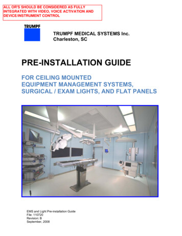
ALL OR'S SHOULD BE CONSIDERED AS FULLYINTEGRATED WITH VIDEO, VOICE ACTIVATION ANDDEVICE/INSTRUMENT CONTROLTRUMPF MEDICAL SYSTEMS Inc.Charleston, SCPRE-INSTALLATION GUIDEFOR CEILING MOUNTEDEQUIPMENT MANAGEMENT SYSTEMS,SURGICAL / EXAM LIGHTS, AND FLAT PANELSEMS and Light Pre-installation GuideFile: 110720Revision: BSeptember, 2008
TRUMPF Medical Systems, Inc.Charleston, South CarolinaTable of ATION RESPONSIBILITIES . 3PROJECT COMPONENTS AND PRE‐INSTALLATION PROCESS . 3SAFETY AND ENVIRONMENTAL CONSIDERATIONS . 4EQUIPMENT MANAGEMENT SYSTEM (EMS) MOUNTING SYSTEMS.42.1TRUMPF PRE‐ENGINEERED EMS MOUNTING SYSTEMS. 42.2DESIGN LOADS FOR EQUIPMENT MANAGEMENT SYSTEMS (EMS) . 52.3ATTACHMENT METHODS FOR TRUMPF EMS MOUNTING SYSTEMS . 52.4STRUCTURAL DEFLECTION CRITERIA (EMS) . 62.5EMS MOUNTING SYSTEM COMPONENTS . 62.6SYSTEM CONFIGURATIONS AND INTERSTITIAL SPAN . 82.6.1EMS Mounting System for 8” Interstitial (Catalog #: 110106). 82.6.2EMS Mounting System for 14” – 47” Interstitial (Catalog #: 110107) . 92.6.3EMS Mounting System for 47” – 59” Interstitial (Catalog #: 110108) . 102.7INSTALLATION OF TRUMPF EMS MOUNTING SYSTEM . 112.7.1Installation of the EMS Mounting Plate. 112.7.2Installation of Threaded Rods or Adjustable Spacers . 112.7.3Installation of Interface Plate for Med. Gas and Electrical Connections. 132.8EMS PNEUMATIC BRAKING SYSTEM . 143.0SURGICAL LIGHT AND FLAT PANEL SYSTEMS . 153.1DESIGN LOADS FOR SURGICAL LIGHT AND FLAT PANEL SYSTEMS . 153.2STRUCTURAL DEFLECTION CRITERIA (LIGHTS AND FLAT PANELS) . 153.3DESIGN ELEVATIONS FOR SUBSTRUCTURE . 163.4TRUMPF SURGICAL LIGHT / FLAT PANEL MOUNTING PLATES . 183.5TRUMPF SURGICAL LIGHT ELECTRICAL AND CONDUIT REQUIREMENTS . 193.5.1Installation of Surgical Light Transformer Enclosures. 193.5.2Transformer Location for Replacement (Renovation) Lights . 203.5.3Required Conduits for Transformers in Enclosures (New Construction) . 213.5.4Required Conduits for Transformers Underneath Cover (Renovation) . 223.5.5Site Preparation for Surgical Light Wall Controls . 234.04.14.24.34.4A.0A.1A.2CEILING MOUNTED EXAM (HELION‐S) LIGHTS . 24DESIGN LOADS FOR CEILING MOUNTED EXAM (HELION‐S) LIGHTS . 24STRUCTURAL DEFLECTION CRITERIA (HELION‐S) . 24DESIGN ELEVATIONS FOR SUBSTRUCTURE (HELION‐S) . 24ELECTRICAL AND CONDUIT REQUIREMENTS (HELION‐S) . 25APPENDIX . 26ROUGH‐IN DRAWINGS AVAILABLE UPON REQUEST . 26CONTACT INFORMATION . 26File: 110720B, September, 2008Page 2 of 26
TRUMPF Medical Systems, Inc.1.0Charleston, South CarolinaIntroductionThis document is a guide to the steps that must be performed in order to properly prepare aproject site for installation of a TRUMPF ceiling suspended system. Covered within this guide arepre-installation requirements for Equipment Management Systems (EMS), surgical light /examination light, and flat panel systems.1.1Pre-installation ResponsibilitiesGenerally, work required above the finished ceiling must be performed by the owner or ownerdesignated contractor. All fixed attachments between TRUMPF mounting systems and buildingsuper-structures must be approved by the project engineer of record. TRUMPF TechnicalService will complete the installation following the conclusion of all required pre-installationactivities as detailed within this guide.1.2Project Components and Pre-installation ProcessComponentSpecificationProvided ByMaterialsProvided ByInstallationPerformed ByTimeline / ProjectPhaseMechanicalContractorWhile ceilings areopenTRUMPFStructural MountingPlates andTRUMPF EMSMounting SystemsLight Power SupplyTransformerEnclosuresMains Power, Video,Data, andCommunication Cablesw/ Required J-boxes &ConduitsTRUMPFAttachment,Substructure, andlateral bracing byStructural Engineer ofRecordLateral Bracing &Substructure (ifReq’d.) by OthersTRUMPFTRUMPFElectricalContractorWhile ceilings areopen during electricalinstallationOwner or ElectricalContractor inaccordance toTRUMPF rough-inmaterialOwner or ContractorElectricalContractorWhile ceilings areopen during electricalinstallIntegration Cabling forVideo and F orTRUMPF assistper contractTerms andConditionsMedical Gas InletTubesTRUMPFTRUMPFMedical GasContractorEMS, Light, or FlatPanel SuspensionTRUMPFTRUMPFTRUMPFFinal EquipmentCertifications – Med.Gas and ElectricalLocal Codes, NEC,and NFPASite InspectionElectrical / Med.Gas Contractorand / or localcode inspectorCables required atTRUMPF 4-weeksprior to shipment or tofield during install percontract Terms andConditionsWhile ceilings areopen during plumbinginstallBased on overallconstruction scheduleFollowing equipmentinstallationFigure #1) Project Responsibility MatrixFile: 110720B, September, 2008Page 3 of 26
TRUMPF Medical Systems, Inc.1.3!Charleston, South CarolinaSafety and Environmental Considerations Many components are heavy. Use extreme caution while unpacking shippingcontainers and installing equipment.All personnel working around energized circuits should be qualified and followingproper safety procedures.All TRUMPF supplied equipment must be stored in clean, dry environments prior toinstallation.Empty packaging material and refuse must be disposed of by the owner inaccordance with the governing regulations of local municipalities.2.0Equipment Management System (EMS) Mounting Systems2.1TRUMPF Pre-engineered EMS Mounting SystemsPicture #1) TRUMPF EMS Mounting SystemsTRUMPF offers pre-engineered mounting solutions for Equipment Management Systems (EMS).TRUMPF boom mounting systems are designed to a 4X factory of safety under the design loadsas specified in Section 2.2.File: 110720B, September, 2008Page 4 of 26
TRUMPF Medical Systems, Inc.2.2Charleston, South CarolinaDesign Loads for Equipment Management Systems (EMS)Fmax.Mbmax.9,200 N (2067 lbf)12,500 Nm ( 9,220 ft-lbs)Figure #2) Design Loads (EMS)The design loads shown above represent the maximum loading scenario for any TRUMPF ceilingmounted Equipment Management System (EMS). TRUMPF recommends designing all mountsinvolving booms to this maximum condition in order to maintain flexibility for future productupgrades. Model specific design loads are also available from TRUMPF Project Engineeringupon request.2.3Attachment Methods for TRUMPF EMS Mounting SystemsSYSTEM WELDED TO STRUCTURESYSTEM ANCHORED TO COMPOSITE DECKSYSTEM BOLTED TO STRUCTURESYSTEM ANCHORED TO STRUCTURAL SLABPicture #2) TRUMPF EMS Mounting System – Attachment MethodsFile: 110720B, September, 2008Page 5 of 26
TRUMPF Medical Systems, Inc.Charleston, South CarolinaThe TRUMPF EMS mounting system may be attached to the building superstructure in thefollowing manners: Welded to superstructure or fabricated substructure.Bolted to superstructure or fabricated substructure.Anchored to structural concrete slab or structural composite deck.Notes:1) A custom mounting plate may be required for direct anchorage into compositedecks.2) (4) 1” x 4” ASTM-A307 bolts with nuts, flat washers, and lock washers arerecommended for bolted attachment methods. Attachment hardware is providedby others.3) The Structural Engineer of Record for the project is ultimately responsible forspecifying and approving all attachment methods. This includes the specificationof weldments, attachment hardware, concrete anchors, and any required lateralbracing.2.4Structural Deflection Criteria (EMS) 2.5Maximum horizontal deflection of substructure at the attachment point of the TRUMPFmounting plate must not exceed 0.1” when subject to horizontal load of 100lbs.Maximum angular deflection of substructure at the attachment point of the TRUMPFmounting plate must not exceed 1/3 from level when subject to the design loads asspecified by TRUMPF.EMS Mounting System ComponentsThe following components are used to create TRUMPF EMS mounting systems. Not all of thecomponents listed will be required for every type of mounting system. TRUMPF ProjectEngineering will provide the contractor with a project specific bill of materials drawing prior to anymounting system installation. EMS Mounting Plate (110037) – Used for attachment of the mounting system to thebuildings structural deck or owner furnished sub-structure.Threaded Rod Assembly (110684) – Used to span interstitial for 11” systems.Adjustable Spacer (337111) – Hexagonal extrusion and threaded rod assembly used tospan interstitial for 14” – 47” systems.Adjustable Spacer Set (337147) - Two piece hexagonal extrusions and threaded rodassemblies used to span interstitial for 47” – 59” and custom systems.Intermediate Stiffener Plate (110444) – Used only with 47” – 59”, and custom systems.Splice Plate (110213) – Used as attachment point for lateral bracing if required.Medical Gas Inlet Tube (TBD) – Used for connection between main supply line andTRUMPF EMS hose.Junction Box (TBD) – Provided by electrical contractor for termination of circuits.Universal Interface Plate (110344) – Used to house medical gas inlet tubes andelectrical junction boxes.File: 110720B, September, 2008Page 6 of 26
TRUMPF Medical Systems, Inc.Charleston, South CarolinaFigure #3) EMS Mounting Plate (110037)Threaded Rod Assy. and Adj. SpacersJ-boxes, Inlet Tubes, Interface PlatePicture #3) EMS Mounting System ComponentsFile: 110720B, September, 2008Page 7 of 26
TRUMPF Medical Systems, Inc.2.6Charleston, South CarolinaSystem Configurations and Interstitial SpanThe configuration of the TRUMPF EMS mounting system will depend on the length of theinterstitial span. Interstitial span is defined by TRUMPF as the distance between the room side ofthe finished ceiling and the top attachment point of the boom mounting system as shown inFigure #3.Figure #4: Determining the Interstitial Span for the TRUMPF Mounting System2.6.1 EMS Mounting System for 8” Interstitial (Catalog #: 110106)Figure #5) 110106 Mounting System Components (see drawing 110106 for complete rough-in)File: 110720B, September, 2008Page 8 of 26
TRUMPF Medical Systems, Inc.Charleston, South CarolinaThe 110106 Mounting System is designed specifically for an 8” interstitial span. The componentswhich make up this system are shown below. Please see drawing 110106 for complete rough-ininformation.Components in 110106 Mounting System:1)2, 3, 6)4)5)7)8)Boom Mounting Plate (110037)Threaded Rod Assembly (110684)Inlet Tube for Pneumatic Brakes (TBD)Medical Gas Inlet Tube (TBD)Junction Box (By Others)Universal Interface Plate (110344)2.6.2 EMS Mounting System for 14” – 47” Interstitial (Catalog #: 110107)Figure #6) 110107 Mounting System Components (see drawing 110107 for complete rough-in)The 110107 Mounting System is designed for interstitial span ranges from 14” – 47” (please referto Figure #4 for calculation of interstitial span). The components which make up this system areshown below. Please see the appendix for complete rough-in information.Components in 110107 Mounting System:1)2)3)4)5)6)7)Boom Mounting Plate (110037)Adjustable Spacer (337111)Medical Gas Inlet Tube (TBD)Inlet Tube for Pneumatic Brakes (TBD)Universal Interface Plate (110344)Junction Box (By Others)Splice Plate (110213) {if required for lateral bracing}File: 110720B, September, 2008Page 9 of 26
TRUMPF Medical Systems, Inc.Charleston, South Carolina2.6.3 EMS Mounting System for 47” – 59” Interstitial (Catalog #: 110108)Figure #7) 110108 Mounting System Components (see Drawing 110108 for complete rough-in)The 110108 Mounting System is designed for interstitial span ranges from 47” – 59” (please referto Figure #4 for calculation of interstitial span). The components which make up this system areshown below. Please see the appendix for complete rough-in information.Components in 110108 Mounting System:1)2)3)4)5)6)7)8)Boom Mounting Plate (110037)Adjustable Spacer Set (337147)Intermediate Stiffener Plate (110444)Medical Gas Inlet Tube (TBD)Junction Box (By Others)Inlet Tube for Pneumatic Brakes (TBD)Universal Interface Plate (110344)Splice Plate (110213) {if required for lateral bracing}File: 110720B, September, 2008Page 10 of 26
TRUMPF Medical Systems, Inc.2.7Charleston, South CarolinaInstallation of TRUMPF EMS Mounting SystemThe TRUMPF EMS mounting system is supplied by TRUMPF but installed by others. Installationof the EMS mounting plate at the top of the system should be performed while the ceilings areopen to ease installation. The complete mounting system will need to be installed prior to thecompletion of the medical gas and electrical supply lines.2.7.1 Installation of the EMS Mounting Plate!The standard EMS mounting plate (110037) weighs approximately 100lbs.Therefore, two installers and a manual lift are required for a safe and properinstallation.The mounting location of the EMS mounting plate should be provided by the project architect, andthe attachment method given by the structural engineer of record.Picture #4) Alignment of EMS Mounting PlateThe alignment of the EMS mounting plate should be parallel to the nearest wall or square to thefloor plan of the room. If there is a ceiling grid present, the EMS mounting plate should beinstalled parallel to the grid.2.7.2 Installation of Threaded Rods or Adjustable SpacersThe standard EMS mounting plate (110037) has (8) M22 tapped holes for attachment of theadjustable spacers or threaded rod assemblies. The M22 mounting studs at the top of theseassemblies are designed to stop just short of protruding through the top side of the plate. Eightthreaded rod or adjustable spacers are required for every installation, and these must be installedwith a target torque of 89 ft-lbs.File: 110720B, September, 2008Page 11 of 26
TRUMPF Medical Systems, Inc.Charleston, South CarolinaTRUMPF adjustable spacers orthreaded rod assemblies can beinserted into the EMS mountingplate by hand, but they must beset to a toque of 89 ft-lbs using alarge torque wrench.Adjustable spacers assembliesare 55mm across flats, and theM22 bolts at the top of thethreaded rod assemblies are30mm across flats.A total of 8 adjustable spacers orthreaded rod assemblies arerequired for every EMSinstallation.Threaded Rod Assemblies (110106S)Spacers (110107 and 110108 Systems)Picture #5) Installing Threaded Rod Assemblies and Adjustable SpacersNotes:1)M16 threaded rods at the lower end of the adjustable spacers should be set to come torest at 3” below the room side of the finished ceiling for EMS installations with standard 4”deep ceiling covers.2)EMS installations with flat ceiling covers will require the M16 threaded rods to be set at 1”above the room side of the finished ceiling.3)Do not use any thread locking agent on TRUMPF mounting systems.4)Please contact TRUMPF Project Engineering for additional clarification.File: 110720B, September, 2008Page 12 of 26
TRUMPF Medical Systems, Inc.Charleston, South Carolina2.7.3 Installation of Interface Plate for Med. Gas and Electrical ConnectionsThe Universal Interface Plate (110344) is designed to house the medical gas inlet tubes forconnection between the main gas supply lines and the flexible hoses from the TRUMPFequipment management system. The Universal Interface Plate and medical gas inlet tubes areprovided by TRUMPF but installed by others. The Universal Interface Plate also provides amounting provision for electrical junction boxes that are provided by others for termination ofcircuit wiring. The Universal Interface Plates are shipped in a flat state, and the tabs that housethe medical gas inlet tubes can be bent either upwards or downwards to a 90 position.The Universal Interface Plate isdesigned to mount Raco 265 (411/16” x 4-11/16” x 2-1/8”)junction boxes or similar.Junction boxes are provided byothers.Medical gas inlet tubes areprovided by TRUMPF. Aseparate inlet tube is providedfor each gas outlet on the EMS.Medical gas inlet tubes areinstalled by others, and thearrangement of the tubes can befield specified, but DISSconnections must face theinterior of the mount.Picture #6) Installing the Universal Interface Plate and Med. Gas Inlet TubesGas inlet tubes are brazed into supply lines via a 1/2” OD copper connection, 1/2” copper tubingis approximately 7” long. Inlet tubes have male DISS connections with internal check valves forconnection to flexible hosing from the equipment management system.File: 110720B, September, 2008Page 13 of 26
TRUMPF Medical Systems, Inc.2.8Charleston, South CarolinaEMS Pneumatic Braking SystemTRUMPF Equipment Management Systems utilize pneumatic braking systems to control armpositioning. A separate supply line must be added to each mount for the pneumatic brakingsystem. TRUMPF will supply a gas inlet tube for each mount according to the type of gas that isselected for the pneumatic braking system. The pneumatic brake inlet tubes will be installed byothers.Notes:1)Pneumatic braking systems can run on either Nitrogen or compressed air.2)Line pressure must be regulated by others to be 55 – 70 psig.3)TRUMPF pneumatic braking systems use 0.004 ft 3 of gas per actuation.4)The braking system is actuated 3-4 times each time that an EMS is repositioned.5)A friction brake prevents arm drift while the EMS is stationary. When repositioning, thebrake bladder is filled and the friction brake is lifted from the bearing surfaceEMS arm is stationary andpneumatic brake bladderremains deflated.EMS a
2.0 Equipment Management System (EMS) Mounting Systems . 2.1 TRUMPF Pre-engineered EMS Mounting Systems . Picture #1) TRUMPF EMS Mounting Systems . TRUMPF offers pre-engineered mounting solutions for Equipment Management Systems (EMS). TRUMPF boom mounting systems are designed to a 4X fac