Transcription
Quick StartPowerFlex 40 AdjustableFrequency AC DriveFRN 5.xx - 6.xxThis Quick Start guide summarizes the basic steps needed to install,start-up and program the PowerFlex 40 Adjustable Frequency AC Drive.The information provided Does Not replace the User Manual and isintended for qualified drive service personnel only.For detailed PowerFlex 40 information including EMC instructions,application considerations and related precautions, refer to thePowerFlex 40 User Manual, Publication 22B-UM001 atwww.rockwellautomation.com/literature.General Precautions!ATTENTION: The drive contains high voltage capacitors which taketime to discharge after removal of mains supply. Before working ondrive, ensure isolation of mains supply from line inputs [R, S, T (L1,L2, L3)]. Wait three minutes for capacitors to discharge to safe voltagelevels. Failure to do so may result in personal injury or death.Darkened display LEDs is not an indication that capacitors havedischarged to safe voltage levels.!!!!ATTENTION: Equipment damage and/or personal injury may resultif parameter A092 [Auto Rstrt Tries] or A094 [Start At PowerUp] isused in an inappropriate application. Do not use this function withoutconsidering applicable local, national and international codes,standards, regulations or industry guidelines.ATTENTION: Only qualified personnel familiar with adjustablefrequency AC drives and associated machinery should plan orimplement the installation, start-up and subsequent maintenance of thesystem. Failure to comply may result in personal injury and/orequipment damage.ATTENTION: This drive contains ESD (Electrostatic Discharge)sensitive parts and assemblies. Static control precautions are requiredwhen installing, testing, servicing or repairing this assembly.Component damage may result if ESD control procedures are notfollowed. If you are not familiar with static control procedures,reference A-B publication 8000-4.5.2, “Guarding Against ElectrostaticDamage” or any other applicable ESD protection handbook.ATTENTION: An incorrectly applied or installed drive can result incomponent damage or a reduction in product life. Wiring or applicationerrors, such as, undersizing the motor, incorrect or inadequate ACsupply, or excessive ambient temperatures may result in malfunction ofthe system.
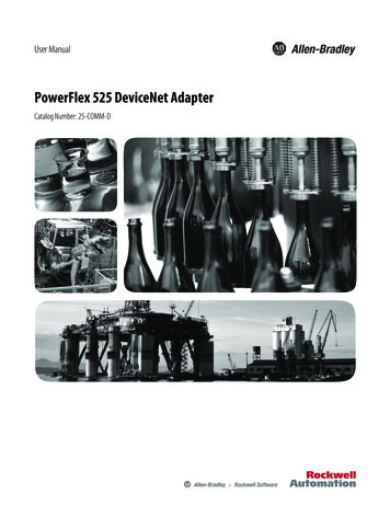
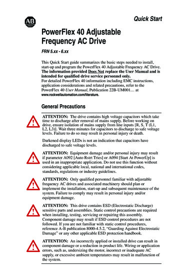
English-2Mounting Considerations Mount the drive upright on a flat, vertical and level surface.FrameBCB (IP66,Type 4X) Screw SizeM4 (#8-32)M5 (#10-24)Screw Torque1.56-1.96 N-m (14-17 lb.-in.)2.45-2.94 N-m (22-26 lb.-in.)DIN Rail35 mm–M6 (#12-24)3.95-4.75 N-m (35-42 lb.-in.)–Protect the cooling fan by avoiding dust or metallic particles.Do not expose to a corrosive atmosphere.Protect from moisture and direct sunlight.Minimum Mounting ClearancesSee Page 21 for mounting dimensions.120 mm(4.7 in.)120 mm(4.7 in.)25 mm(1.0 in.)Closest object thatmay restrict air flowthrough the drive heatsink and chassis120 mm(4.7 in.)120 mm(4.7 in.)Mounting Option ANo clearance requiredbetween drives.Mounting Option BAmbient Operating TemperaturesAmbient TemperatureMinimumMaximumEnclosure RatingIP20, NEMA/UL Type Open40 C (104 F) IP66, NEMA/UL Type 4X-10 C (14 F)IP30, NEMA/UL Type 1(1)50 C (122 F) IP20, NEMA/UL Type Open(1)Minimum MountingClearancesUse Mounting Option AUse Mounting Option AUse Mounting Option BUse Mounting Option BRating requires installation of the PowerFlex 40 IP 30, NEMA/UL Type 1 option kit.
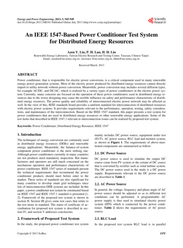
English-3Typical GroundingR/L1S/L2T/L3U/T1V/T2W/T3SHLDDisconnecting MOVsTo prevent drive damage, the MOVs connected to ground shall bedisconnected if the drive is installed on an ungrounded distributionsystem where the line-to-ground voltages on any phase could exceed125% of the nominal line-to-line voltage. To disconnect these devices,remove the jumper shown in the figures below.1. Turn the screw counterclockwise to loosen.2. Pull the jumper completely out of the drive chassis.3. Tighten the screw to keep it in place.Jumper LocationIP20, NEMA/UL Type OpenIP66, NEMA/UL Type 4XImportant: Tighten screw after jumper removal.Phase to Ground MOV RemovalR/L1Three-PhaseAC Input S/L2T/L3Jumper1234
English-4CE ConformityRefer to the PowerFlex 40 User Manual for details on how to complywith the Low Voltage (LV) and Electromagnetic Compatibility (EMC)Directives.Specifications, Fuses and Circuit BreakersDrive RatingsOutput Ratings Input RatingsCatalogNumber(1)kW (HP)PowerDissipationBranch Circuit ProtectionMin.Enclosure140M MotorVolume(5) IP20 OpenVoltageAmps Range kVA Amps Fuses Protectors(3) (4) Contactors (in.3)Watts100 - 120V AC ( 10%) – 1-Phase Input, 0 - 230V 3-Phase Output22B-V2P3x104 0.4 (0.5)2.390-1321.15 9.015140M-C2E-C16 100-C1216554022B-V5P0x104 0.75 (1.0)5.090-1322.45 20.335140M-D8E-C20 100-C2316556022B-V6P0x104 1.1 (1.5)6.090-1323.040140M-F8E-C32 100-C3716558024.0200 - 240V AC ( 10%) – 1-Phase(2) Input, 0 - 230V 3-Phase Output22B-A2P3x104 0.4 (0.5)2.3180-264 1.15 6.010140M-C2E-B63 100-C0916554022B-A5P0x104 0.75 (1.0)5.0180-264 2.45 12.020140M-C2E-C16 100-C1216556022B-A8P0x104 1.5 (2.0)8.0180-264 4.018.030140M-D8E-C20 100-C2316558522B-A012x104 2.2 (3.0)12.0180-264 5.525.040140M-F8E-C32 100-C37206912540200 - 240V AC ( 10%) – 3-Phase Input, 0 - 230V 3-Phase Output22B-B2P3x104 0.4 (0.5)2.3180-264 1.15 2.56140M-C2E-B40 100-C07165522B-B5P0x104 0.75 (1.0)5.0180-264 2.45 5.710140M-C2E-C10 100-C0916556022B-B8P0x104 1.5 (2.0)8.0180-264 4.015140M-C2E-C16 100-C121655851259.522B-B012x104 2.2 (3.0)12.0180-264 5.515.525140M-C2E-C16 100-C23165522B-B017x104 3.7 (5.0)17.5180-264 8.621.030140M-F8E-C25 100-C23165518022B-B024x104 5.5 (7.5)24.0180-264 11.8 26.140140M-F8E-C32 100-C37206923522B-B033x104 7.5 (10.0)33.0180-264 16.3 34.660140M-G8E-C45 100-C60206930535380 - 480V AC ( 10%) – 3-Phase Input, 0 - 460V 3-Phase Output22B-D1P4x104 0.4 (0.5)1.4342-528 1.41.83140M-C2E-B25 100-C07165522B-D2P3x104 0.75 (1.0)2.3342-528 2.33.26140M-C2E-B40 100-C0716555022B-D4P0x104 1.5 (2.0)4.0342-528 4.05.710140M-C2E-B63 100-C0916557022B-D6P0x104 2.2 (3.0)6.0342-528 5.97.515140M-C2E-C10 100-C09165510022B-D010x104 4.0 (5.0)10.5342-528 10.3 13.020140M-C2E-C16 100-C23165516022B-D012x104 5.5 (7.5)12.0342-528 11.8 14.225140M-D8E-C20 100-C23206917522B-D017x104 7.5 (10.0)17.0342-528 16.8 18.430140M-D8E-C20 100-C23206921022B-D024x104 11.0 (15.0) 24.0342-528 23.4 26.050140M-F8E-C32 100-C432069300460 - 600V AC ( 10%) – 3-Phase Input, 0 - 575V 3-Phase Output22B-E1P7x104 0.75 (1.0)1.7414-660 2.12.36140M-C2E-B25 100-C0916555022B-E3P0x104 1.5 (2.0)3.0414-660 3.65 3.86140M-C2E-B40 100-C0916557022B-E4P2x104 2.2 (3.0)4.2414-660 5.25.310140M-D8E-B63 100-C09165510022B-E6P6x104 4.0 (5.0)6.6414-660 8.18.315140M-D8E-C10 100-C09165516022B-E9P9x104 5.5 (7.5)9.9414-660 12.1 11.220140M-D8E-C16 100-C16206917522B-E012x104 7.5 (10.0)12.2414-660 14.9 13.725140M-D8E-C16 100-C23206921022B-E019x104 11.0 (15.0) 19.0414-660 23.1 24.140140M-F8E-C25 100-C302069300(1)(2)In the Catalog Numbers listed “x” represents enclosure type. Specifications are valid for allenclosure types. IP66, NEMA/UL Type 4X drive ratings are only available as Frame B drives.200-240V AC - 1-Phase drives are also available with an integral EMC filter. Catalog suffixchanges from N104 to N114. Filter option is not available for IP66, NEMA/UL Type 4X rated drives.
English-5(3)(4)(5)The AIC ratings of the Bulletin 140M Motor Protector Circuit Breakers may vary. See Bulletin 140MMotor Protection Circuit Breakers Application Ratings.Manual Self-Protected (Type E) Combination Motor Controller, UL listed for 208 Wye or Delta, 240Wye or Delta, 480Y/277 or 600Y/347. Not UL listed for use on 480V or 600V Delta/Delta, cornerground, or high-resistance ground systems.When using a Manual Self-Protected (Type E) Combination Motor Controller, the drive must beinstalled in a ventilated or non-ventilated enclosure with the minimum volume specified in thiscolumn. Application specific thermal considerations may require a larger enclosure.ApprovalsInput/Output RatingsDigital Control Inputs (Input Current 6mA)SRC (Source) Mode:18-24V ON0-6V OFFSNK (Sink) Mode:0-6V ON18-24V OFFLISTED 966XULOutput Frequency: 0-400 Hz (Programmable)Efficiency: 97.5% (Typical) INLISUL508CC IND CO N T EQTED 966XULCSA 22.2D CO N T EQEMC Directive 89/336LV:EN 50178, EN 60204EMC: EN 61800-3, EN 50081-1, EN 50082-2Analog Control Inputs4-20mA Analog: 250 ohm input impedance0-10V DC Analog: 100k ohm input impedanceExternal Pot: 1-10k ohms, 2 Watt minimumControl OutputProgrammable Output (form C relay)Resistive Rating: 3.0A at 30V DC, 3.0A at 125V AC, 3.0A at 240V ACInductive Rating: 0.5A at 30V DC, 0.5A at 125V AC, 0.5A at 240V ACOpto Outputs30V DC, 50mANon-inductiveAnalog Outputs (10 bit)0-10V, 1k ohm Min.4-20mA, 525 ohm Max.Fuses and Circuit BreakersRecommended Fuse Type: UL Class J, CC, T or Type BS88; 600V (550V) or equivalent.Recommended Circuit Breakers: HMCP circuit breakers or equivalent.Protective FeaturesMotor Protection: I2t overload protection - 150% for 60 Secs, 200% for 3 Secs (Provides Class 10 protection)Overcurrent: 200% hardware limit, 300% instantaneous faultOver Voltage:100-120V AC Input – Trip occurs at 405V DC bus voltage (equivalent to 150V AC incoming line)200-240V AC Input – Trip occurs at 405V DC bus voltage (equivalent to 290V AC incoming line)380-460V AC Input – Trip occurs at 810V DC bus voltage (equivalent to 575V AC incoming line)460-600V AC Input – Trip occurs at 1005V DC bus voltage (equivalent to 711V AC incoming line)Under Voltage: 100-120V AC Input – Trip occurs at 210V DC bus voltage (equivalent to 75V AC incoming line)200-240V AC Input – Trip occurs at 210V DC bus voltage (equivalent to 150V AC incoming line)380-480V AC Input – Trip occurs at 390V DC bus voltage (equivalent to 275V AC incoming line)460-600V AC Input – If P042 3 “High Voltage” trip occurs at 487V DC bus voltage (344V AC incoming line);If P042 2 “Low Voltage” trip occurs at 390V DC bus voltage (275V AC incoming line)Control Ride Through: Minimum ride through is 0.5 Secs - typical value 2 SecsFaultless Power Ride Through: 100 millisecondsDynamic BrakingInternal brake IGBT included with all ratings except No Brake versions. Refer to Appendix B of the PowerFlex 40 User Manualfor DB resistor ordering information.
English-6Power WiringPower Wire RatingRecommended CopperWireUnshielded 600V, 75 C (167 F) THHN/THWN15 Mils insulated, dry locationShielded 600V, 75 C or 90 C (167 F or 194 F) RHH/RHW-2Anixter OLF-7xxxxx,Belden 29501-29507 orequivalentAnixter 7V-7xxxx-3GShielded Tray rated 600V, 75 C or 90 C (167 F or 194 F)Shawflex 2ACD/3ACD orRHH/RHW-2equivalentPower Terminal BlockB FrameC FrameR/L1 S/L2 T/L3 U/T1 V/T2 W/T3R/L1 S/L2 T/L3 U/T1 V/T2 W/T3DC- DC BR BR-Terminal (1)DescriptionR/L1, S/L21-Phase InputP2P1DC- DC BR BR-R/L1, S/L2, T/L3 3-Phase InputU/T1To Motor U/T1V/T2To Motor V/T2W/T3 To Motor W/T3Switch any two motorleads to changeforward direction.DC Bus Inductor Connection (C Frame drives only.)P2, P1The C Frame drive is shipped with a jumper betweenTerminals P2 and P1. Remove this jumper only when a DCBus Inductor will be connected. Drive will not power upwithout a jumper or inductor connected.DC , DC-DC Bus ConnectionBR , BR-Dynamic Brake Resistor ConnectionSafety Ground - PE(1)Important: Terminal screws may become loose during shipment. Ensure that allterminal screws are tightened to the recommended torque before applying power tothe drive.Power Terminal Block SpecificationsFrameMaximum Wire Size (2) Minimum Wire Size (2) TorqueB5.3 mm2 (10 AWG)C(2)8.4 mm2 (8 AWG)1.3 mm2 (16 AWG)1.7-2.2 N-m (16-19 lb.-in.)1.3 mm2 (16 AWG)2.9-3.7 N-m (26-33 lb.-in.)Maximum/minimum sizes that the terminal block will accept - these are notrecommendations.
English-7Input Power ConditionsInput Power ConditionCorrective ActionLow Line Impedance (less than 1% line reactance) Install Line Reactor(2) or Isolation TransformerGreater than 120 kVA supply transformer or Bus Inductor – 5.5-11 kW(7.5-15 HP) drives onlyLine has power factor correction capacitorsLine has frequent power interruptions Install Line Reactor or Isolation TransformerLine has intermittent noise spikes in excess of6000V (lightning)Ungrounded distribution system Remove MOV jumper to ground. or Install Isolation Transformerwith grounded secondary ifnecessary.240V open delta configuration (stinger leg)(1) Install Line ReactorPhase to ground voltage exceeds 125% of normalline to line voltage(1)(2)For drives applied on an open delta with a middle phase grounded neutral system, thephase opposite the phase that is tapped in the middle to the neutral or earth isreferred to as the “stinger leg,” “high leg,” “red leg,” etc. This leg should be identifiedthroughout the system with red or orange tape on the wire at each connection point.The stinger leg should be connected to the center Phase B on the reactor. Refer to thePowerFlex 40 User Manual for specific line reactor part numbers.Refer to Appendix B of the PowerFlex 40 User Manual for accessory orderinginformation.I/O Wiring Recommendations (3)Wire Type(s)(4)DescriptionBelden 8760/9460(or equiv.)0.8 mm2 (18AWG), twisted pair, 100% shield300Vwith drain.60 degrees C0.8 mm2 (18AWG), 3 conductor, shielded for (140 degrees F)remote pot only.Belden 8770(or equiv.)(3)(4)Minimum InsulationRatingIf the wires are short and contained within a cabinet which has no sensitive circuits,the use of shielded wire may not be necessary, but is always recommended.Stranded or solid wire.I/O Terminal Block SpecificationsFrameMaximum Wire Size (5) Minimum Wire Size (5) TorqueB&C1.3 mm2 (16 AWG)(5)0.2 mm2 (24 AWG)0.5-0.8 N-m (4.4-7 lb.-in.)Maximum / minimum that the terminal block will accept - these are notrecommendations.Refer to the PowerFlex 40 User Manual for recommendations onmaximum power and control cable length.
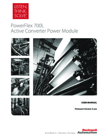
English-8Control Terminal BlockControl Wiring Block DiagramEnableJumper(4)010203SNKSRC040506070809 24V11 10V121314Relay N.O.Relay CommonRelay N.C.R10-10VR20/4-20mA151617R330V DC50mANon-inductive0-10V0-20mAR1 R2 R3Analog Output Select1819StopTypicalSRC Wiring(1)(4)Start/Run FWDTypicalSNK Wiring(2)Direction/Run REVDigital CommonDigital Input 1Digital Input 2Digital Input 3Digital Input 4Opto Common 24V DC 10V DC0-10V (or 10V) InputAnalog CommonPot must be1-10k ohm2 Watt Min.4-20mA InputAnalog OutputCommonOpto Output 1(3)24VOpto Output 2RS485 ShieldENBL01 02 03 04 05 06 07 08 09SNK11 12 13 14 15 16 17 18 19EnableJumper(4)RS485(DSI)SRC(1)30V DC 125V AC 240V portant: I/O Terminal 01 is always a coast tostop input except when P036 [Start Source] is set to3-WirePer P037Per P037“3-Wire” or “Momt FWD/REV” control. In three wire2-WirePer P037Coastcontrol, I/O Terminal 01 is controlled by P037 [StopRS485 PortPer P037CoastMode]. All other stop sources are controlled by P037[Stop Mode].Important: The drive is shipped with a jumper installed between I/O Terminals 01 and 11. Removethis jumper when using I/O Terminal 01 as a stop or enable input.P036 [Start Source]StopI/O Terminal 01 StopKeypadPer P037Coast(2)Two wire control shown. For three wire control use a momentary inputon I/O Terminal 02 tocommand a start. Use a maintained inputfor I/O Terminal 03 to change direction.(3)When using an opto output with an inductive load such as a relay, install a recovery diode parallelto the relay as shown, to prevent damage to the output.(4)When the ENBL jumper is removed, I/O Terminal 01 will always act as a hardware enable, causinga coast to stop without software interpretation. Refer to the PowerFlex 40 User Manual for moreinformation.
English-9Control I/O Terminal DesignationsNo. SignalDefaultDescriptionParam.R1Relay N.O.FaultNormally open contact for output relay.A055R2Relay Common–Common for output relay.R3Relay N.C.FaultNormally closed contact for output relay.Analog Output SelectDIP Switch0-10VSets analog output to either voltage or current. Setting must matchA065 [Analog Out Sel].Sink/SourceDIP SwitchSource (SRC)Inputs can be wired as Sink (SNK) or Source (SRC) via DIP Switchsetting.A055P036 (1)01Stop (1)CoastThe factory installed jumper or a normally closedinput must be present for the drive to start.02Start/Run FWDNot Active03Direction/Run REV Not ActiveCommand comes from the integral keypad by default. P036, P037To disable reverse operation, see A095 [ReverseP036, P037,Disable].A09504Digital Common–For digital inputs. Electronically isolated with digitalinputs from analog I/O and opto outputs.05Digital Input 1Preset FreqProgram with A051 [Digital In1 Sel].A05106Digital Input 2Preset FreqProgram with A052 [Digital In2 Sel].A05207Digital Input 3LocalProgram with A053 [Digital In3 Sel].A05308Digital Input 4Jog ForwardProgram with A054 [Digital In4 Sel].A05409Opto Common–For opto-coupled outputs. Electronically isolated withopto outputs from analog I/O and digital inputs.11 24V DC–Referenced to Digital Common.Drive supplied power for digital inputs.Maximum output current is 100mA.12 10V DC–Referenced to Analog Common.Drive supplied power for 0-10V externalpotentiometer.Maximum output current is 15mA.13 10V In (2)Not ActiveFor external 0-10V (unipolar) or 10V (bipolar) input P038,supply (input impedance 100k ohm) orA051-A054,potentiometer wiper.A123, A13214Analog Common–For 0-10V In or 4-20mA In. Electronically isolatedwith analog inputs and outputs from digital I/O andopto outputs.154-20mA In (2)Not ActiveFor external 4-20mA input supply(input impedance 250 ohm).16Analog OutputOutFreq 0-10The default analog output is 0-10V. To covert to aA065, A066current value, change the Analog Output Select DIPSwitch to 0-20mA. Program with A065 [Analog OutSel]. Max analog value can be scaled with A066[Analog Out High].Maximum Load: 4-20mA 525 ohm (10.5V)0-10V 1k ohm (10mA)17Opto Output 1MotorRunningProgram with A058 [Opto Out1 Sel]A058, A059,A06418Opto Output 2At FrequencyProgram with A061 [Opto Out2 Sel]A061, A062,A06419RS485 (DSI) Shield –(1)(2)P038P038,A051-A054,A132Terminal should be connected to safety ground - PEwhen using the RS485 (DSI) communications port.See Footnotes (1) and (4) on page 8.0-10V In and 4-20mA In are distinct input channels and may be connected simultaneously.Inputs may be used independently for speed control or jointly when operating in PID mode.
English-10Prepare For Drive Start-Up!ATTENTION: Power must be applied to the drive to perform thefollowing start-up procedures. Some of the voltages present are atincoming line potential. To avoid electric shock hazard or damage toequipment, only qualified service personnel should perform thefollowing procedure. Thoroughly read and understand the procedurebefore beginning. If an event does not occur while performing thisprocedure, Do Not Proceed. Remove All Power including usersupplied control voltages. User supplied voltages may exist even whenmain AC power is not applied to the drive. Correct the malfunctionbefore continuing.Before Applying Power to the Drive 1. Confirm that all inputs are connected to the correct terminals and aresecure. 2. Verify that AC line power at the disconnect device is within the ratedvalue of the drive. 3. Verify that any digital control power is 24 volts. 4. Verify that the Sink (SNK)/Source (SRC) Setup DIP Switch is set tomatch your control wiring scheme. See page 8 for location.Important: The default control scheme is Source (SRC). The Stopterminal is jumpered (I/O Terminals 01 and 11) to allowstarting from the keypad. If the control scheme is changedto Sink (SNK), the jumper must be removed from I/OTerminals 01 and 11 and installed between I/O Terminals01 and 04. 5. Verify that the Stop input is present or the drive will not start.Important: If I/O Terminal 01 is used as a stop input, the jumperbetween I/O Terminals 01 and 11 must be removed.Applying Power to the Drive 6. Apply AC power and control voltages to the drive. 7. Familiarize yourself with the integral keypad features (see next page)before setting any Program Group parameters.If a fault appears on power up, refer to page 20 for an explanation of thefault code. For complete troubleshooting information, refer to thePowerFlex 40 User Manual.
English-11Start, Stop, Direction and Speed ControlFactory default parameter values allow the drive to be controlled fromthe integral keypad. No programming is required to start, stop, changedirection and control speed directly from the integral keypad.Important: To disable reverse operation, see A095 [Reverse Disable].Changing the Speed Reference of an IP66, NEMA/UL Type 4X rateddriveWhen a Display Group parameter, for example, d001 [Output Freq] isdisplayed, and P038 [Speed Ref] is set to A069 [Internal Freq], you canchange the internal frequency using the Up Arrow and Down GRAMFAULTWhen the internal frequency is being adjusted, its value is displayed andthe Hertz LED flashes. Any changes are saved immediately. The displaythen returns to the Display Group parameter previously shown.TIP: By default, the speed reference of an IP66, NEMA/UL Type 4Xrated drive is set to the internal frequency, A069 [Internal Freq].TIP: You can also change the speed reference by editing the parameterA069 [Internal Freq] in program mode. For details on how to enter theprogram mode, see the section, “Viewing and Editing Parameters.”The default value of A069 [Internal Freq] is 0 Hz. For IP20 ratedPowerFlex 40 drives, the default value of this parameter is 60 Hz.
English-12Integral HERTZFAULT➎Basic Program GroupConsists of most commonly usedprogrammable functions.➑➐DescriptionDisplay Group (View Only)Consists of commonly viewed drive operatingconditions.➒Advanced Program GroupConsists of remaining programmable functions.Fault DesignatorConsists of list of codes for specific faultconditions. Displayed only when fault is present.No. LED➊ Run/DirectionStatusLED StateSteady RedFlashing Red➋AlphanumericDisplaySteady RedFlashing Red➌➍➎➏➐Displayed UnitsSteady RedDescriptionIndicates drive is running and commanded motor direction.Drive has been commanded to change direction. Indicatesactual motor direction while decelerating to zero.Indicates parameter number, parameter value, or fault code.Single digit flashing indicates that digit can be edited.All digits flashing indicates a fault condition.Indicates the units of the parameter value being displayed.Program StatusSteady RedIndicates parameter value can be changed.Fault StatusFlashing RedIndicates drive is faulted.Pot StatusSteady GreenIndicates potentiometer on Integral Keypad is active.(1)Start Key Status Steady GreenNo. Key➑➒NameEscapeDescriptionBack one step in programming menu.Cancel a change to a parameter value and exit ProgramMode.SelectAdvance one step in programming menu.Select a digit when viewing parameter value.Up ArrowScroll through groups and parameters.Down ArrowIncrease/decrease the value of a flashing digit.Used to adjust internal frequency of IP66, NEMA/UL Type 4Xrated drives only when a Display Group parameter is shownand P038 [Speed Reference] is set to internal frequency,A069 [Internal Freq].EnterAdvance one step in programming menu.Save a change to a parameter value.Potentiometer(1) Used to control speed of drive. Default is active.Controlled by parameter P038 [Speed Reference].StartReverseStop(1)Indicates Start key on Integral Keypad is active.The Reverse key is also active unless disabled by A095[Reverse Disable].Used to start the drive. Default is active.Controlled by parameter P036 [Start Source].Used to reverse direction of the drive. Default is active.Controlled by parameters P036 [Start Source] and A095[Reverse Disable].Used to stop the drive or clear a fault.This key is always active.Controlled by parameter P037 [Stop Mode].IP66, NEMA/UL Type 4X rated drives are not equipped with a potentiometer.
English-13See the PowerFlex 40 User Manual for more information on parameters.Viewing and Editing ParametersThe last user-selected Display Group parameter is saved when power is removed and is displayed bydefault when power is reapplied.The following is an example of basic integral keypad and display functions. This example provides basicnavigation instructions and illustrates how to program the first Program Group parameter.StepKey(s)1. When power is applied, the last user-selectedDisplay Group parameter number is brieflydisplayed with flashing characters. The displaythen defaults to that parameter’s current value.(Example shows the value of d001 [OutputFreq] with the drive stopped.)Example DisplaysVOLTSAMPSHERTZPROGRAM2. Press Esc once to display the Display Groupparameter number shown on power-up. Theparameter number will flash.FAULTVOLTSAMPSHERTZPROGRAMFAULT3. Press Esc again to enter the group menu. Thegroup menu letter will flash.VOLTSAMPSHERTZ4. Press the Up Arrow or Down Arrow to scrollthrough the group menu (d, P and A).or5. Press Enter or Sel to enter a group. The rightdigit of the last viewed parameter in that groupwill flash.or6. Press the Up Arrow or Down Arrow to scrollthrough the parameters that are in the group.or7. Press Enter or Sel to view the value of aparameter. If you do not want to edit the value,press Esc to return to the parameter number.or8. Press Enter or Sel to enter program mode toedit the parameter value. The right digit willflash and the Program LED will illuminate if theparameter can be edited.or9. Press the Up Arrow or Down Arrow to changethe parameter value. If desired, press Sel tomove from digit to digit or bit to bit. The digit orbit that you can change will . Press Esc to cancel a change. The digit willstop flashing, the previous value is restored andthe Program LED will turn off.OrPress Enter to save a change. The digit will stopflashing and the Program LED will turn off.VOLTSAMPSHERTZPROGRAM11. Press Esc to return to the parameter list.Continue to press Esc to back out of theprogramming menu.FAULTVOLTSAMPSHERTZPROGRAMIf pressing Esc does not change the display,then d001 [Output Frequency] is displayed.Press Enter or Sel to enter the group menu.The Basic Program Group contains the most commonly changed parameters.FAULT
English-14See the PowerFlex 40 User Manual for more information on parameters.Display Group ParametersNo.ParameterMin/MaxDisplay/Optionsd001 [Output Freq]0.0/[Maximum Freq]0.1 Hzd002 [Commanded Freq]0.0/[Maximum Freq]0.1 Hzd003 [Output Current]0.00/(Drive Amps 2)0.01 Ampsd004 [Output Voltage]0/Drive Rated Volts1 VACd005 [DC Bus Voltage]Based on Drive Rating1 VDCd006 [Drive Status]0/1 (1 Condition True)Bit 3Deceleratingd007- [Fault x Code]d009F2/F122F1d010 [Process Display]0.00/99990.01 – 1d012 [Control Source]0/9Digit 1 Speed Command(See P038; 9 “Jog Freq”)d013 [Contrl In Status]0/1 (1 Input Present)Bit 3DB Trans OnBit 2Stop InputBit 1Dir/REV InBit 0Start/FWD Ind014 [Dig In Status]0/1 (1 Input Present)Bit 3Digital In 4Bit 2Digital In 3Bit 1Digital In 2Bit 0Digital In 1d015 [Comm Status]0/1 (1 Condition True)Bit 3Comm ErrorBit 2DSI OptionBit 1TransmittingBit 0Receivingd016 [Control SW Ver]1.00/99.990.01d017 [Drive Type]1001/99991d018 [Elapsed Run Time]0/9999 Hrs1 10 Hrsd019 [Testpoint Data]0/FFFF1 Hexd020 [Analog In 0-10V]0.0/100.0%0.1%d021 [Analog In 4-20mA]0.0/100.0%0.1%d022 [Output Power]0.00/(Drive Power 2)0.01 kWd023 [Output Powr Fctr]0.0/180.0 deg0.1 degd024 [Drive Temp]0/120 degC1 degCd025 [Counter Status]0/99991d026 [Timer Status]0.0/9999 Secs0.1 Secsd028 [Stp Logic Status]0/71d029 [Torque Current]0.00/(Drive Amps 2)0.01 AmpsBit 2AcceleratingBit 1ForwardBit 0RunningDigit 0 Start Command(See P036; 9 “Jog”)Smart Start-Up with Basic Program Group ParametersThe PowerFlex 40 is designed so that start up is simple and efficient. The Program Groupcontains the most commonly used parameters. Stop drive before changing this parameter.No.ParameterP031 [Motor NP Volts]Min/MaxDisplay/OptionsDefault20/Drive Rated Volts1 VACBased on Drive Rating1 Hz60 HzSet to the motor nameplate rated volts.P032 [Motor NP Hertz]15/400 HzSet to the motor nameplate rated frequency.P033 [Motor OL Current] 0.0/(Drive Rated Amps 2) 0.1 AmpsBased on Drive RatingSet to the maximum allowable motor current.P034 [Minimum Freq]0.0/400.0 Hz0.1 Hz0.0 HzSets the lowest frequency the drive will outputcontinuously.P035 [Maximum Freq]0/400 Hz1 Hz60 Hz0 “Keypad”(1)1 “3-Wire”2 “2-Wire”3 “2-W Lvl Sens”4 “2-W Hi Speed”5 “Comm Port”6 “Momt FWD/REV”0Sets the highest frequency the drive will output.P036 [Start Source]0/6Sets the control scheme used to start the drive.(1) When active, the Reverse key is also activeunless disabled by A095 [Reverse Disable].
English-15See the PowerFlex 40 User Manual for more information on parameters. Stop drive before changing this t0/90 “Ramp, CF”(1)1 “Coast, CF”(1)2 “DC Brake, CF”(1)3 “DCBrkAuto,CF”(1)4 “Ramp”5 “Coast”6 “DC Brake”7 “DC BrakeAuto”8 “Ramp EM B,CF”9 “Ramp EM Brk”(1) Stop input also clears active fault.00 “Drive Pot”1 “InternalFreq”2 “0-10V Input”3 “4-20mA Input”4 “Preset Freq”5 “Comm Port”6 “Stp Logic”7 “Anlg In Mult”01 (IP66, Type 4X)0.1 Secs10.0 Secs0.1 Secs10.0 Secs0 “Ready/Idle”1 “Factory Rset”0P042 [Voltage Class]2/3Sets the voltage class of 600V drives.2 “Low Voltage” (480V)3 “High Voltage” (600V)3P043 [Motor OL Ret]0 “Disabled”1 “Enabled”0P037 [Stop Mode]Active stop mode for all stop sources [e.g. keypad,run forward (I/O Terminal 02), run reverse (I/OTerminal 03), RS485 port] except as noted below.Important: I/O Terminal 01 is always a coast tostop input except when P036 [Start Source] is setfor “3-Wire” control. When in three wire control, I/OTerminal 01 is controlled by P037 [Stop Mode].P038 [Speed Reference]0/7Sets the source of the speed reference to thedrive.Important: When A051 or A052 [Digi
Use Mounting Option B 50 C (122 F) IP20, NEMA/UL Type Open Use Mounting Option B 25 mm (1.0 in.) 120 mm (4.7 in.) 120 mm (4.7 in.) 120 mm (4.7 in.) 120 mm (4.7 in.) Mounting Option A No clearance required between drives. Mounting Option B Closest object that may restrict air flow through the drive heat sink and chassis