Transcription
CHAIN LINK FENCEWIND LOAD GUIDE FOR THESELECTION OF LINE POST ANDLINE POST SPACING(WLG 2445)Updated June, 2016Copyright (C) 2016 Chain Link Fence Manufacturers Institute All Rights Reserved.10015 Old Columbia Road Suite B215Columbia, MD 21046Ph: 301-596-2583 Fax: 301-596-2594Email: clfmihq@aol.comwww.chainlinkinfo.org
CLFMI Technical Support TeamTo get answers to your questions regarding the content or usage of the information containedin this publication, contact one of these fence industry professionals for assistance.BILL ULLRICHCHUCK NAEGELESTEVE PETERSTED EYSENBACHDON FINNTOM STANEKBILL PETERSONemail: bullrich.link@comcast.netemail: canaegele@aol.comemail: smpeters@ldpeters.comemail: teysen@spsfence.comemail: dfinn@westerntube.comemail: tom.stanek@wheatland.comemail: bill@richardsfence.comPhone: 410-849-2610Phone: 570-586-7260Phone: 914-576-5100Phone: 1-800-451-2612Phone: 310-537-6300Phone: 1-800-257-8182Phone: 330-773-0423Published by:Chain Link Fence Manufacturers Institute (CLFMI)10015 Old Columbia Road Suite B-215 Columbia, MD 21046Phone: (301) 596-2583 Fax: (301) 596-2594E-mail: info@chainlinkinfo.orgWebsite: www.chainlinkinfo.org
TABLEOF CONTENTS Introduction .1 Factors Which Influence the Size and Spacing of Line Posts2 Figure 1, Line Post Spacing Details .3 Methodology .4 to 5 How to Use the Guide.6 Examples .7 to 9 Tables .10 to 22 Table 1; Line Post Selection Guide for 105 MPH Wind Table 2; Line Post Selection Guide for 110 MPH Wind Table 3; Line Post Selection Guide for 120 MPH Wind Table 4; Line Post Selection Guide for 130 MPH Wind Table 5; Line Post Selection Guide for 140 MPH Wind Table 6; Line Post Selection Guide for 150 MPH Wind Table 7; Line Post Selection Guide for 160 MPH Wind Table 8; Line Post Selection Guide for 170 MPH Wind Table 9; Mesh and Fabric Size Coefficients "Cf1" Table 10; Wind Exposure Category Coefficients "Cf2" Table 11; Ice Exposure Effect Probability Coefficients "Cf3" Table 12; Line Post Material Properties Table Table 13; Wind Speed I Velocity Pressure Table Figure 26.5-1C, Minimum Basic Wind Speeds Map.23 to 24 Appendix .25 to 32 References .33
INTRODUCTIONThe Chain Link Fence Manufacturers Institute (CLFMI) would like to acknowledgeLeonard Engineering, Inc. fo r the technical analys is of this Guide, as well as members ofthe CLFMI Technical Committee, for their complete and thorough editing effort on theorginal version. Also, further acknowledgem ent is extended to the American Society ofCivil Engineers (ASCE) for agreeing to the use of its copyrighted materials, CLFMIwishes to extend special recognition to Charles Naegele, Chair of the CLFMI TechnicalCommittee, for his leadership in the production of this Guide.This Guide is intended to provide background information in the forms of charts andtables to assist fence designers and installers in the appropriate selection of fencing lineposts for chain link fencing. However, because conditions vary from site to site, theinformation in the Guide should not be relied upon without the evaluation of a qualifiedprofessional engineer.PLEASE READ THE DISCLAIMER.The Guide includes eight tables for the spacings of line posts exposed to wind speeds of105 MPH up to and including 170 MPH. These tables are based on the applicable ASCE7-10 wind load standards. The spacing values listed in the eight tables must be adjustedusing appropriate and selected coefficients to account for the size of the fabric gaugeand mesh size, wind exposure and the probability for the development of icing conditionsat that location. Moreover, the tables do not take into account wind speeds exceeding170 MPH, which may occur in category 5 hurricanes, tornadoes, at high elevations, or asthe result of explosions.Seven of the more commonly used fabric wire gage sizes and seven of the mostcommonly used mesh sizes when used in any combination and acted upon by theseveral sets of wind pressures (not wind speed or velocity) offers the user choices in theselection and/or specifying line posts based on local wind conditions, economics,aesthetics and functionality of other design criteria established for a specific application. Itshould be noted that this guide is specifically designed for the use with chain link fencesystems only and is not intended for use with other fence designs.The guide considers the following assumptions as being applicable in the designanalysis based on the wind loading criteria outlined in ASCE 7-10, "Minimum LoadDesign Criteria for Buildings and Other Structures", Chapter 26, Wind Loads:General Requirements and Chapter 29, Wind Loads on Other Structures andBuilding Appurtenances—MWFRS. Wind is acting in a direction normal to the plane of the fencing fabric andapplied on the fabric side of the line post.Tension wire or rail at the base and top of the fence accommodates thenormal tensile loading being applied to take up vertical sag of the fence.Additionally the line posts are considered to be embedded in the ground surface inaccordance with the minimum size and depth established according to the 2009International Building Code and ASTM F567, "Standard Practice for Installation ofChain Link Fence". All posts are considered to be embedded in concrete, minimum2,500 psi, air-entrained, of a depth consistent with local soil types and conditions.(1)
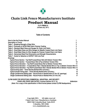
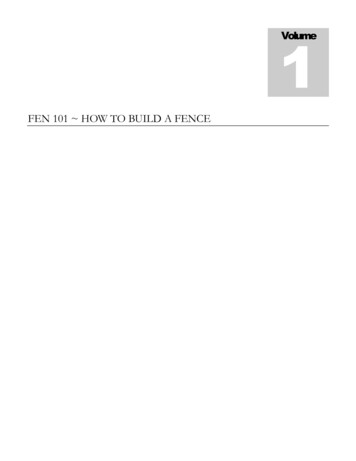
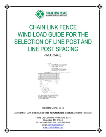
FACTORS WHICH INFLUENCE THE SIZE AND SPACING OF LINE POSTS* HEIGHT OF FENCE The height of the fence influences the actual amount of wind force that must beresisted by the post and the required anchorage to the ground. The fence height times the line post spacing setsthe total force acting on a solid panel of the fence which is transferred to the line posts and then into the footing. STYLE AND SIZE OF FABRIC The style and size of fabric determines the net surface area of the solidfence panel exposed to the wind pressure which in turn must possess adequate tensile strength to transfer thedeveloped loading to the supporting members of the fence assembly; i.e., line posts, top rail and base tensionwire. MATERIAL STRENGTH AND SHAPE OF POST Material strength and shape of post determines the sizeof posts and their spacing which will provide the required resistance to the maximum expected wind forces thatmay develop over the anticipated normal life-span of the installation and to remain serviceable subsequent to themaximum wind event. UPDATED FOOTING ANALYSIS AS RELATED TO SOIL TYPE AND BEARING LOADS The type ofsoil that will be encountered at the site of the fence installation will influence the post size and spacing by way ofthe passive soil pressures that can reasonably be expected to resist the tendency for the line posts to overturnand also to remain in an essentially plumb position after the wind event. For footing design criteria, it is advisableto contact a competent geotechnical professional for the appropriate soils information at the particular site. Theminimum depth of footings in accordance with ASTM F567 is 24" plus an additional 3" for each one (1) foot offence height over 4 feet. The 2009 International Building Code, (Eq. 18-1) is utilized to determine the requiredfooting embedment depth, up to a maximum embedment depth of 12'-0" below finish gradeVARIABLES AND DEFINITIONS for the FORMULA FOR DETERMING FOOTING DEPTHP Resultant concentrated wind force applied to postc Distance above top of footing at which “P” is applied to postD Post footing embedment depth below finish graded Diameter of post footingS1 Allowable lateral soil-bearing pressureH Fence post height above top of footingD 0.5A * { 1 [1 (4.36 * c ) / A ) ]1/2 }A 2.34P/S1*dSEE THE CALCULATION EXAMPLE 3 ON PAGE (8) FOR AN ILLUSTRATION OF THIS ANALYSISThe table listed below (which is also found on page 32 of this Guide) shows the Presumptive Soil Load BearingValues for calculations to determine footing sizes using this updated approach, which includes lateral as well asvertical factors. WIND PRESSURE Wind pressure is the most dominant factor that influences the post size and spacingsince it is the only force that can reasonably be predicted and will be acting on the posts under normal conditions.Reference Table 13 for values of various wind speeds and pressures. Wind pressure in itself is further influencedby other factors; i.e., geographical region, exposure, topography and ground surface features in the local area.*Reference Figure I, "LINE POST(2)
(2)ASCE 7 10 (FIGURE 26.5 1C)LINE POST – SEE TABLE 12 FORSCHEDULE OF TYPES, SIZES, ANDMATERIALS OF POST.CIRCULAR CONCRETE FOOTINGS. EMBEDMENTDEPTH DEPENDENT ON TYPE OF SOIL THATEXISTS ON SITE. THE O.D. (“D”) OF THE FOOTINGIS EXPRESSED AS 4 (pd) OR 3 (pd) (WHERE “pd” POST OD) DEPENDING ON THE SIZE OF THEPOST DIAMETER.Ref. ASTM F567 and 2009 IBC (Eq. 18-1)METHODOLOGY
METHODOLOGYThe methodology applied to develop the tabular values of "S", the unmodified maximum spacingsof line post materials, sizes and shapes most commonly employed in the chain link fencingindustry, for the fence heights and wind speeds was based on wind loading criteria outlined inASCE 7-10, Chapter 26, Wind Loads: General Requirements and Chapter 29, Wind Loadson Other Structures and Building Appurtenances—MWFRS, excerpts of which areincluded in the Appendix of this Guide.This application of the recommended loading criteria as it applies to fence construction takes intoconsideration all factors that influence the wind forces applied to the primary force resistingelement of the fence; in this instance the line posts, which in-turn must transfer that loading to theground. This guide is based on the assumption of a solid panel of fencing and uses multiplicationfactors for various percentages of free area of the fence panel.To establish the magnitude of the wind force that will be acting on the line post, it must first beestablished what the net surface area of the fence panel will be; i.e., the solid panel area, "h x S"less the void spaces within the fence. The net surface area of the wire fabric is what the windforce impinges on and is directed on to the post. Since the panel of the fence is essentially aperforated plane, it is necessary to quantify the actual solid surface to void area. The area of wiresurface was determined by establishing the number of diamonds in a square foot of fabric andtotaling the length of wire in that area. This is the value used in combination with the computed windvelocity pressures that when applied as a load to the fence post acting as a flagpole design; i.e., avertical cantilever, fixed at its base to the footing and ground.Now with the value known for the wind velocity pressure that develops for each of the selectedranges of the eight Wind Speed Classes of 105 MPH through 170 MPH acting under normalconditions for a Wind Exposure Category "B", these forces are then applied to the face area of thefence panel assumed to be solid. With the height "H" of the fence known, the only variable thatneeds to be established to set the total gross area "Ag" of the panel is the line post spacing "S".The values of "S" were generated based on the loading applied to the post as a vertical cantilever,in a similar fashion as the "classic" flagpole design.Table 1 through Table 8 are set up for fence heights that range from 3 feet up to and including 20feet and twenty-six combinations of line post sizes and types, in a solid panel configuration. The"S" values were computed on the basis of their physical, material properties and formulas listedin Table 12 with a limiting value based on the maximum allowable stress.To account for the variations in the fabric wire sizes and sizes of mesh, Table 9 was developedand lists the Coefficient "Cf1" which accounts for the variation and is based on a ratio of net areato gross area of a solid panel for each of the commonly used styles employed in the industry.(4)
The base program for the line post spacing was set up using the condition where Wind ExposureCategory "B" is the normal situation. To account for the other two Wind Exposure Categories, "C"and "D", Table 10 was developed to list the Coefficient "Cf2" which is a ratio of the Wind ExposureCoefficient "Kz" for Exposure "B" to the other two exposure coefficients as listed in ASCE 7-10,Table 29.3-1.In Table 11, Ice Effect Probability Coefficient "Cf3" is included in the guide and was set up usingarbitrary values to permit the designer the ability to make an intelligent decision relative to hisperception and experience as to the probability that a severe icing condition may developconcurrent with the listed maximum wind speed for that particular geographical location for nonsolid fencing.Figure 26.5-1C from ASCE 7-10 shows wind speed categories in the range of 105 MPH to 170MPH, but also includes special wind speed regions and a 180 MPH wind speed for use in Guam.This guide provides values of wind speeds that cover the entire range of velocities that may beencountered in the continental United States and Hawaii but does not include Guam and willrequire separate analysis to determine wind speeds in the special wind speed regions asdetermined by local jurisdictions and/or case study. For any installations determined to haveintermediate wind speeds, it is acceptable to interpolate linearly.The user of this guide is advised that he may want to consider use of the full allowable stress ofthe material being employed which has a built-in
Th e minimum depth of footings in accordance with ASTM F567 is 24" plus an additional 3" for each one (1) foot of fence height over 4 feet. The 2009 International Building Code, (Eq. 18-1) is utilized to determine the required footing embedment depth, up to a maximum embedment depth of File Size: 2MBPage Count: 38