Transcription
Concrete Inspection and Repair Strategy forOnshore Wind TurbinesFrancis Mongeon , P.EngConstruction Chemicals – Master Builders SolutionsKey Account Manager - Power, Infrastructure & Industry
This presentation reviews key industry best practices toperform quality construction and could help establishingthe basis of inspection programs related to concretefoundations, grouts and concrete components.2The information, views and opinions presented or expressed during this presentation are those of the presenter or derived from published third party
Why monitoring and inspecting ?MonitoringObserve and check the progress or quality of (something) over a period of time; keep undersystematic reviewCondition assessment / condition evaluationInvestigation and appraisal of the condition of a structureNon destructive testing (NDT)Examination of materials and structures in ways that do not impair future usefulness andserviceability in order to detect, locate, and measure discontinuities, defects, and otherimperfections to assess integrity, properties, and uniformity, and to measure geometricalcharacteristics.
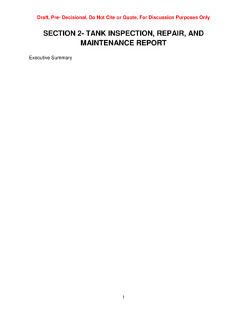
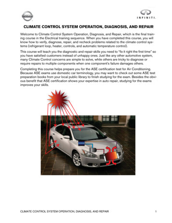
“A wind turbine is a complete, dynamic system: interactions are felt from blade tip to foundation. Betterunderstanding of the relations and capturing them in models helps reduce material use and furtherincrease the cost effectiveness of turbines”EWEA 2013 conference announcementWeatherRotationBendingTorsionAxial loadVibrations Loads need to be transferred bythe grout connecting the tower tothe foundation structure. A careful design and selection ofthe grouting material is thereforeof utmost importance. Safe and durable installation ofwind turbines largely depend onthe materials which connect thetower to its base / foundation.
Current Situation Current tests for concrete and grouts on projects Compressive strengths (concrete and grout) Cement grout: ASTM C-1107 (confined cubes in mold) Not CSA A23.2, not ASTM C-109 Epoxy grout: ASTM C-579 Slump testing (concrete) No fatigue tests requirements (eg. DNV-OS-C502-458) in design, butsuggested in CSA Guide to Canadian wind turbine codes and standards Shim packs stay in place (contrary to API RP 686) No expansion joints (API RP 686)
Inspection and Monitoring Approach Global visual inspection Detection of obvious or extensivedamage Performed at distance (eg.Binoculars) Close visual inspection Examination of specific surfacearea (eg. Drones) Non-destructive inspection/testing Destructive testing Instrumentation based conditionmonitoring
Onshore wind turbine installationsAnchor cage design foundationsCurrent situation Increasing number of failures Concrete foundation Grout materials Failures occur within 1 – 2 years Complex installation prone to mistakesMajor causes: Too low characteristic strength Need meeting specs Too slow strength development “Good enough” No safety factor built-in Not resistant to loads Thermal Mechanical
Onshore wind turbine installationsCan design foundations - ChallengesCurrent situationIncreasing number of failures observed in foundation areas 30% of all installed wind turbine installations have revealed problems Failures occur within 3 – 5 yearsCauses: Dynamic loads - load cyclesDesign mistakesMaterial selection “use the same as last job”Ever growing wind turbines
Objective of Concrete Repairs Concrete repairs is directly linked to the quality of the inspection and assessmentperformed Not all NDE tools will work for all issues. Examiner needs to have a comprehensive knowledge of the tools and techniques that areavailable. Common techniques include: In-situ concrete strength (relative strength comparison unless correlated with laboratorystrength tests, e.g. core compressive strength tests) Location and extent of reinforcement Location and extent of concrete cracking Severity, location and delaminations due to reinforcement corrosion Location, size and distribution of r frost damage Location and extent of void/honeycombing Thickness of concrete members Presence and rate of reinforcement corrosion activity
Visual Inspection GeneralDescription of StructureMaterial usedNature of Environmental and LoadingConditions Distress indicators Present condition of structure (surfacecondition only)
Non - Destructive Evaluation Techniques Improved understanding of concrete conditions prior to repairBetter repair methodology Repair design Repair materials Repair methodsAlternative to drilling and coring
ICRI 210.4 Guide for Non-destructive Evaluation Methods for Condition Assessment,Repair, and Performance Monitoring of Concrete Structures
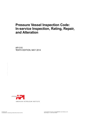
Sonic Echo (ASTM D5882), Impulse Response and Impedance Imaging Sonic echo reads wavesecho Impulse Response readsfrequency domain off sonicecho tests Impedance imaging can giveidealized axisymmetric 3Dpile shapeSource: ICRI Guideline 210.4-2009
Ultrasonic Pulse-Echo Short ultrasonic pulses (50-70 kHz)transmitted to concrete Reflects changes in stiffness Reflects changes in density, eg.Voids, cracking, honeycombing,etc Helps to locate flaws, henceidentifying repair location and sizes
Cracks in concrete and groutSituation Fatigue occurs when material issubjected to repeated loading andunloading Cracks begin to form Cracks reach a critical size andfurther damage occur, eg.Fracture, water ingress, failure,etc.Solutions (ACI 224.1)1) rout and seal the crack, thus treating it as a joint;2) establish a joint that will accommodate the movement and then inject the crack withepoxy or other suitable material;3) install additional support or reinforcement at the crack location to minimizemovement.Source: Cracks in onshore wind power foundations , causes and consequences. Elforsk rapport 11:56, Manouchehr Hassanzadeh, January 2012
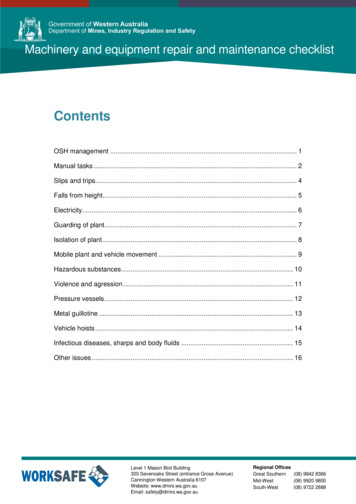
Example of cracks in concrete and groutShrinkage cracking (Non-Critical)Segregation / Separation (Critical)Excess material (Non-Critical)Voids(Critical)
When to inspect ? During construction (first 28 days) Surface sealing of surface cracks Repair as needed Surface preparation for repairs (!) – ICRI Higher frequency in first year to identify earlyproblems Non-critical cracks VS critical cracks MTO/AASHTO’s : 0.3mm for injection Active cracks vs passive cracks (ACI 224.1) Reduce/Increase frequency as needed On damaged foundation, inspection to be carriedevery 6 months Verify success of repairs Every climate is different and every project is different Need to build historical data in Canada Large country Different project locations (eg. Ontario vs BC)Camera inspection
No expansion joints (API RP 686) Inspection and Monitoring Approach Global visual inspection Detection of obvious or extensive damage Performed at distance (eg. Binoculars) Close visual inspection Examination of specific surface area (eg. Drones) Non-destructive inspection/testing Destructive testing Instrumentation based condition monitoring . Onshore wind .