Transcription
Structural Analysis ReportStructural Analysis: Self-Supporting Triangular Crank-Up TowerTower Model:HDX-689Design Code: IBC 2009 (TIA-222-G)Basic Wind Velocity:90mphExposureCIce:Topographic Category:Structure Classification:Max. Allowable Antenna Wind Load (lbs) - Unfactored:Max. Allowable Antenna Weight (lbs):Max. Allowable Effective Antenna Wind Area (sq. ft.):None1140723025.2Note: The maximum antenna values shown above include theantenna, rotator, and any other items placed at the top of the tower.For purposes of these calculations the antenna was placed 1 ft. above thetop of the tower.Date Prepared:Prepared By:3/10/2014Remigio Fernandez-Garcia, P.E.Sheet 1 of 1099 W. Ropes Ave - Woodlake, CA 93285 - Ph: 559-564-6000THIS DOCUMENT CONTAINS PROPRIETARY INFORMATION AND SHALL NOT BE USED OR REPRODUCED OR ITS CONTENT DISCLOSED, IN WHOLEOR IN PART, WITHOUT THE PRIOR WRITTEN CONSENT OF US TOWER CORPORATION1
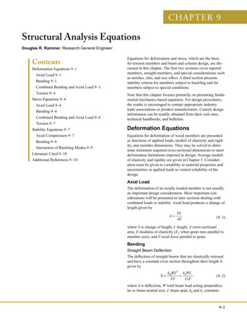
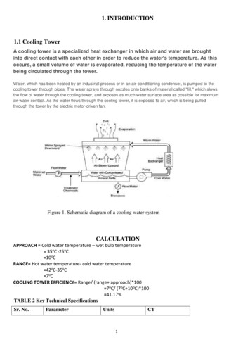
7/16" SOLID ROD2" OD Tube Mast.See cover sheet for max. allowableantenna wind load and area @ 1 FT.above top of tower.17'CO - AX CABLE DIA. (in)MAX. QUANTITY7/8"11/2" SOLID ROD4'17'5/8" SOLID ROD4'SIZE PIPE 2.875" OD X 0.276" PIPE 2.375" OD XWALL0.218" WALLGONSIZE AL7/8" SOLID ROD3/4" SOLID RODDIALEGSECTIONNO.NO. 10 BASENO. 9NO. 8PIPE 1.9" OD X 0.2"WALLNO. 7NO. 6 TOPPIPE 1.66" OD X 0.191" PIPE 1.315" OD X 0.179"WALLWALLHDX-689 TOWER ELEVATION89' 17'4'17'16 11/1619 15/1623 3/44'28 1/434 1/421'Plan ViewNo ScaleGround Level11" max.Elevation ViewTHIS DOCUMENT CONTAINS PROPRIETARYINFORMATION AND SHALL NOT BE USEDOR REPRODUCED OR ITS CONTENTSDISCLOSED, IN WHOLE OR IN PART,WITHOUT THE PRIOR WRITTEN CONSENTOF US TOWER CORPORATION.No Scale2
General Notes:Tower Model:HDX-6891. All work shall be in conformance with the requirements of the "International Building Code - 2009" and"Structural Standards for Antenna Supporting Structures and Antennas ANSI/TIA-222-G",by the Telecommunications Industry Association.2. Steel design is per the requirements of ANSI/TIA-222-G and the Americal Institute of Steel ConstructionSpecification for Structural Steel Buildings, ANSI/AISC 360-05.3. All concrete shall have a minimum compressive strength of 2500 psi at 28 days unless notedotherwise. All concrete shall conform to the requirements of the International Building Code andreferenced edition of ACI 318. Slump shall not exceed 4-1/2 inches.4. Reinforcing steel shall be intermediate grade deformed bars conforming to ASTM A-615.No. 4 bars and smaller shall be Grade 40, No. 5 bars and larger shall be Grade 60. All reinforcingdetails, placement etc. shall conform to the requirements of the International Building Code andACI 318. No welding allowed.5. All reinforcing steel, anchor bolts, dowels and other inserts etc. shall be securely anchored inplace, in the required positions, prior to pouring concrete.6. Steel fabrication and erection shall conform to the requirements of the AISC Manual of SteelConstruction and the Telecommunications Industry Association (as referenced in note 1 & 2 above).7. All welding shall be performed by AWS certified welders for each type of weld used. Using theGMAW welding process with ER70S-6 welding wire.8. All tower section lift cables & guy cables shall be 7 x 19 Aircraft cable with the following minimumstrengths:Cable diameter (in)Minimum Strength 8009. The wind load of the antenna(s) shall not exceed the load shown in these calculations.The Owner of the tower shall assume full liability for verification of the antenna loading.10. This tower is designed to be used in its fully extended position. Unless otherwise noted.11. The design of the hoist system is not with in the scope of these calculations and shall be designedby others.12.This tower has not been designed to meet any twist or sway criteria.13. The Owner shall verify that the quantity and size of waveguide / Coax cables match the valuesused in these calculations.14. The engineering and design of the antennas are not with-in the scope of these calculations.15. Installations on hills, escarpments and other special wind areas is not with-in the scope ofthese calcuations.16. Seismic analysis is not with-in the scope of these calculations. Unless noted otherwise.17. US Tower Corp. recommends that the installation of this tower and its foundation be performed by aProfessional, licensed Contractor with experience installing these types of structures.18. The Contractor is responsible for conducting all construction in accordance with all Federal, State,OSHA, and Local laws and ordinances. The Contractor is also responsible for checking the site forunderground facilities prior to the start of work.19. US Tower Corp. and it's Engineers shall not be responsible for errors and omissions in the projectnot in conformance with these calculations and the Codes and Standards referenced here-in.20. US Tower Corp. and it's Engineers accept no responsibility for field inspection during constructionnor for the method of construction.21. The Owner shall assume full responsibility & liability for the periodic inspection of all tower section liftcables & guy cables. Any cable with any sign of distress or excessive stretch shall be replaced immediately.22. The information contained in these calculations is the property of US Tower Corp. and shallonly be used to obtain an installation permit. Any other use shall be authorized by US Towerin writing prior to utilizing the information contained herein.23. This tower has not been designed for snow or ice loading per TIA-G T. 2-3, Structure Class 1The tower shall be fully retracted prior to any snow or ice event. Unless noted otherwise.24. Foundation design covers F0,S0, P0, C0 & C1 exposure classes. If local conditions are known todiffer, a qualified local professional engineer shall provide the foundation design.25. Foundation Design does not include considerations for frost depth or high ground water level.THIS DOCUMENT CONTAINS PROPRIETARY INFORMATION AND SHALL NOT BE USED OR REPRODUCED OR ITS CONTENT DISCLOSED, INWHOLE OR IN PART, WITHOUT THE PRIOR WRITTEN CONSENT OF US TOWER CORPORATION3
Code & Material SpecificationsTower Model:HDX-689Governing Codes, Stresses, and Materials (Min.)International Building CodeTIA-222-GAISC Spec for Structural Steel BldgsACI 3182009 Edition (Occ. Cat. II)ANSI/TIA-222-GANSI/AISC 360-052008 EditionStructural Steel(All plates, bars, angles)ASTM A36(F-y 36 ksi)(Min. F-y for plates - 42 ksi)Structural PipeASTM A53 Gd. B, A500 Gd. B(F-y 50 ksi for tower legs)Structural Tubing (HSS)ASTM A500 Gd. B (F-y 46 ksi)ASTM A513 Type 1A (F-y 42 ksi)WeldingAWS D1.1-08GMAW w/ ER70S-6 wire perAWS A5.18Hot-Dip GalvanizingHardwareASTM A123ASTM A153Bolts: Tower & AccessoriesASTM A325Reinforced Concrete2500 psi strength @ 28 daysExposure Class F0, S0, P0, C0 & C1Reinforcing SteelASTM A615Gd. 40 for #4 & smaller dia.Gd. 60 for 5 & larger dia.Anchor RodsASTM F1554 Gd. 36or ASTM A-36Foundation & SoilsLateral Bearing Pressure1500 psf Bearing (TL DL LL)100 psf/ft of depthTHIS DOCUMENT CONTAINS PROPRIETARY INFORMATION AND SHALL NOT BE USED OR REPRODUCED OR ITS CONTENTDISCLOSED, IN WHOLE OR IN PART, WITHOUT THE PRIOR WRITTEN CONSENT OF US TOWER CORPORATION4
Tower Section PropertiesTower Model:Note: If a tower section is not in the tower being designed theninput 0 for section length and top & bottom lap lengths.Design per TIA-222-GAll units are in lbs. and inches U.O.N.Tower Height (ft):89Ice t (in):0Density (pcf):56Design Ice t (in):0Tower section No.:HDX-689Design Thickness Modifier:1.00345678910Lgth. of Section (ft):Face width (C.L.):Leg dia.:Leg Thkn's: Spec.Leg Thkn's: DesignLeg .27650000Web dia:Web F-y:Web spacing: (legunsupported length)Web 4031252117312621.5Web clear width:Web L:No. of diagonal 3650.3757880.3757680.3754880.375Top Lap (ft):Bottom Lap (ft):No. of additionallap diagonal webs:Top plate depth:Bot plate depth:Plate Thkn's:Yellow No Ice ConditionGreen With Ice ConditionAppurtenance @ top of Section: (Coax arms need not be included since R-a 0.1)Weight (lbs):00000000Area - No Ice (sq. ft.):00000000Area - w/ Ice (sq. ft.):00000000C-f, (TIA Tbl 2-8):1.21.21.21.21.21.21.21.2Conc. EPA No Ice:00000000Conc. EPA w/ Ice:00000000Projected Areas Outside Lap Areas:Section L (ft) Used:00Section PA (sqft/ft):0.0000.000Section PA (sqft/ft):0.0000.00000.0000.000Projected Areas at Laps:Lap PA (sqft/ft):Lap 3 4:Lap 4 5:Lap 5 :Legs:Webs:Anchors:Misc.:Total weight:Total weight:000000170.5310.531Lap 6 7:Lap 7 8:Lap 8 .801171.2231.2231.9662.3582.7921.9662.3582.792Lap9 871267380380348439817510611631163THIS DOCUMENT CONTAINS PROPRIETARY INFORMATION AND SHALL NOT BE USED OR REPRODUCED OR ITS CONTENT DISCLOSED, INWHOLE OR IN PART, WITHOUT THE PRIOR WRITTEN CONSENT OF US TOWER CORPORATION5
61Ant. Height AboveTop of Tower (ft):0.87511.20.088Kzq-z(basic)w (plf) orP (lb)Wght. / Cable (lb/ft): 0.30Total Wght (lb):27Co-ax Cable Data:Cable dia. (in):No. of cables:C-a:Cable Proj. AreaAntenna & Mast / Mount Data:Antenna Area (ft2):21Force Coefficient C-f:1.2EPA (ft 2):25.2Ant. Mt. wt. 61226125502942Shear(lbs)2481.20.800Lift cableforce 777777771353135313531841184118412123No ICEMomentP-Delta(ft-lbs) Mom. (ft-lbs)Table 3 - EIA(sq.ft. / ft.):Mast Dia. (in):Mast Lgth (in):Force Coeff. C-f:EPA (ft -h:I:Kd:f:Zg:alfa:Kz-min:H 9.50.850N.A.111No IceNo IceNo IceNo 029226125502942No IceNo IceNo IceNo IceNo IceNo IceNo IceNo IceNo IceNo IceNo Ice661671No IceNo Ice0661LoadCondition651671Controlling Loading & ConditionShearMomentLift Cable(lbs)(ft-lbs)Force (lbs)Topographic constantTerrain constantTopo wind speed up factorHeight reduction factorHt. of crest above surrounding terrainExposure category coefficientExposure category coefficientExposure category coefficientTopographic coefficientWind direction probablility factorImportance factorGust factorTHIS DOCUMENT CONTAINS PROPRIETARY INFORMATION AND SHALL NOT BE USED OR REPRODUCED OR ITS CONTENT DISCLOSED, IN WHOLE OR IN PART, WITHOUT THE PRIOR WRITTEN CONSENT OF US TOWER CORPORATIONTower Section Weights: (No Ice)SectionWeight(lbs)Co-ax Wt:27(at top of 21Top of 30.00089891.23518.94030.00089891.23518.940Top of 89891.23518.940Top of 89891.23518.940Top of 7280.51.20918.5416Top of 75561.51.14217.5216Top of 93844.51.06716.3716Top of 82127.50.96414.7918Top of .3110.18.550.85013.0323Note: Top of concentrated load applied at the top of the tower section.Wind Velocicity Coeficient2.01*(z/Zg) 2/aKz z 15'q-z 0.00256 * Kz * Kzt * Kd * I * G-h * V 2TowerProjected AnalysiszSectionAreaheight (ft) height (ft)90C18911.61.2Wind velocity (mph):Exposure:Topo Category:Tower Height (ft):Structure Classif.:Load Factor - Wind:Load Factor - Dead:Design per TIA-222-GWind LoadsTower Model:HDX-689Tower Loading - Shear & Moments
7308Weight at Top (lbs):Section Vert. ComponentWt. (lb): of Guy Cables (lb):38505680695096401395000000013040.22Cable force per face:Cable CSI:17080.41Cable force per face:Cable CSI:Cable fForce Section: 10Cable CSI:Cable force per face:Note:1. At the bottom tower section input the No. of faces w/ cable the no. of tower sections -1. (i.e. For a tower made up of 6 sectionsyou would input 5 as the no. of faces w/ cable.)Pulley Frame - Tower Section: NASum F-vp:0 ( Lift cable force for section analysis)Anchor Frame-Tower Section: NACable dia (in):0.25Cable MBS:7000No. of faces w/cable:1F-v CFtot:0N/A0N/A0N/A0THIS DOCUMENT CONTAINS PROPRIETARY INFORMATION AND SHALL NOT BE USED OR REPRODUCED OR ITS CONTENT DISCLOSED, IN WHOLE OR IN PART, WITHOUT THE PRIOR WRITTEN CONSENT OF USTOWER CORPORATIONPulley Frame-Tower Section:10Sum F-vp:4628 ( Lift cable force for section analysis)Anchor Frame-Tower Section: 9Cable dia (in):0.25Cable MBS:7000No. of faces w/cable:4F-v CFtot:6832Pulley Frame-Tower Section:9Sum F-vp:5868 ( Lift cable force for section analysis)Anchor Frame-Tower Section: 8Cable dia (in):0.3125Cable MBS:9800No. of faces w/cable:3F-v CFtot:3912Cable Force Section: 1Cable CSI:Cable Force Section: 90.16Cable CSI:Cable force per face:Pulley Frame-Tower Section:NASum F-vp:0 ( Lift cable force for section analysis)652Cable force per face:Anchor Frame-Tower Section: NACable dia (in):0.25Cable MBS:7000No. of faces w/cable:1F-v CFtot:0Pulley Frame-Tower Se
TIA-222-G. ANSI/TIA-222-G: AISC Spec for Structural Steel Bldgs. ANSI/AISC 360-05: ACI 318. 2008 Edition: Structural Steel . ASTM A36 (All plates, bars, angles) (F-y 36 ksi) (Min. F-y for plates - 42 ksi) Structural Pipe : ASTM A53 Gd. B, A500 Gd. B (F-y 50 ksi for tower legs) Structural Tubing (HSS) ASTM A500 Gd. B (F-y 46 ksi) ASTM A513 Type 1A (F-y 42 ksi) Welding. AWS D1.1-08: GMAW .File Size: 537KBPage Count: 13