Transcription
Machining ProcessesIME 240
Material Removal Processes Machining is the broad term used to describe removal ofmaterial from a workpiece Includes Cutting, Abrasive Processes (grinding),Advanced Machining Processes (electrical, chemical,thermal, hydrodynamic, lasers) Automation began when lathes were introduced in 1700s Now have computer numerical control (CNC) machines Machining operations are a system consisting of: Workpiece – material, properties, design, temperatureCutting tool – shape, material, coatings, conditionMachine tool – design, stiffness & damping, structureFixture – workpiece holding devicesCutting parameters – speed, feed, depth of cutIndependentvariables
Range of Material Removal calLiquidChemical idtoolECMmachininggasLiquid/Gaseous(granular)high pressure jetThermalGaseousFlame cuttingJet cuttingPlasma usorVacuumLaser beam machiningElectron beam machiningIon beam machining
Material Removal Processes Material removal processes are often required aftercasting or forming to: Improve dimensional accuracy Produce external and internal geometric features, sharp corners, orflatness not possible with forming or shaping Obtain final dimensions and surfaces with finishing operations Obtain special surface characteristics or textures Provide the most economical means of producing a particular part Limitations, because material removal processes: Inevitably waste material Generally require more energy, capital, and labor than forming orshaping operations Can have adverse effects on the surface quality and properties,unless carried out properly, Generally take longer than shaping a product with other processes
Types of Machining Process Single Cutting Edge (Point) Processes Multi-Cutting Edge (Point) Processes Random Point Cutting Processes –Abrasive Machining Within each category the basic motions(kinematics) differentiate one process fromanother
Machine Tool Motions Primary motion thatcauses cutting to takeplace. Feed motion thatcauses more of thepart surface to bemachined Rotations and/ortranslations of theworkpiece or cuttingtool
Single Point Machining Operations
Planing Machine Primary motion istranslation of theworkpiece Feed motion istranslation of the toolincrementally betweencuts
Shaping Machine Primary motion istranslation of the tool Feed motion istranslation of theworkpiece betweencuts
Turning OperationsPrimary motion is rotation of theworkpieceFeed motion is translation of the cuttingtool – continuous driven by spindlerotation
TurningTurning istheprocessformachiningroundworkpieces ona lathe
Workpieces Made by Turning
Lathe Componentsor, guidewaysor slideways
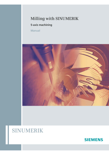
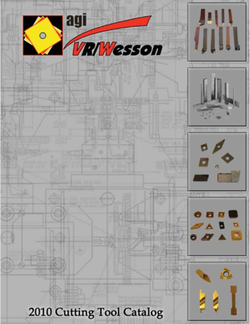
CNCLathewithTurrets(a)Figure 22.11 (a) A turret with sixdifferent tools for inside-diameterand outside-diameter cutting andthreading operations. (b) A turretwith eight different cutting tools.Source: Monarch Machine ToolCompany.(b)
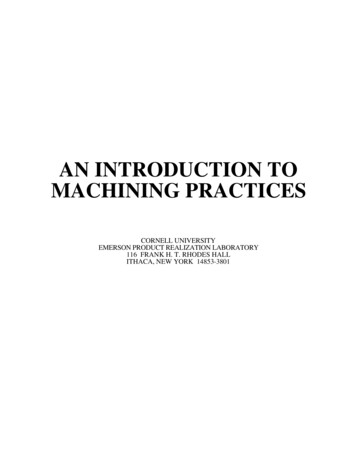
Workholding Devices3-jaw and 4-jaw ChucksMandrels
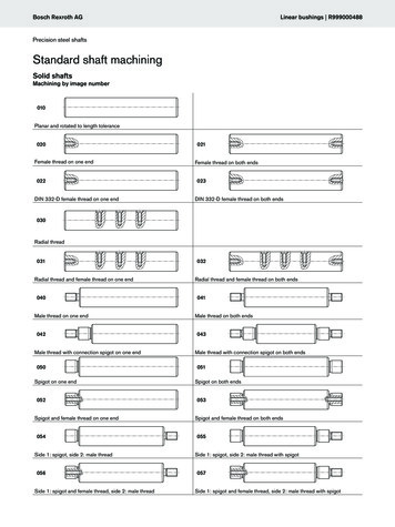
Workholding Devices – Collets and Face Plates
Turning Formulae Material removal rate (MRR) is the volume of materialremoved per unit time (mm3/min or in3/min) Do D fMRR Davg dfN 2 dfN Cutting speed, V πD0Nlt fNCutting time (t)not includingtool approachand retraction.
Power for Machining Power required atcutting tool MRR* Specific cuttingpower Power at motor power at cuttingtool/ mechanicalefficiency of drivesystem
Turning ParametersTABLE 22.3N Rotational speed of the workpiece, rpmf Feed, mm/rev or in/revv Feed rate, or linear speed of the tool along workpiece length, mm/min or in/min fNV Surface speed of workpiece, m/min or ft/min π o N (for maximum speed) π Davg N (for average speed)l Length of cut, mm or in.Do Original diameter of workpiece, mm or in.Df Final diameter of workpiece, mm or in.Davg Average diameter of workpiece, mm or in. (Do Df ) /2d Depth of cut, mm or in. ( Do - Df ) /2t Cutting time, s or min l/f N33MRR mm /min or in /min π Davg d fNTorque Nm or lb ft ( Fc )( Davg /2 )Power kW or hp (Torque) (ω , where ω 2π radians/minNote: The units given are those that are commonly used; however, appropriate units must beused and checked in the formulas.D)
Turning Considerations Design parts for ease of fixturing and clamping (avoid thin, slenderparts) Specify wide tolerances and surface finishes if possible Avoid sharp corners, tapers, and major dimensional variations Use near-net-shape forming to reduce machining cycle times Design features that only need standard cutting tools, inserts, andtoolholders Select materials with good machinability Provide good support and stiffness in the turning operation Adjust parameters if chatter occursTABLE 22.9ProblemTool breakageExcessive tool wearRough surface finishDimensional variabilityTool chatterProbable causesTool material lacks toughness; improper tool angles; machine tool lacks stiffness; worn bearings andmachine components; cutting parameters too high.Cutting parameters too high; improper tool material; ineffective cutting fluid; improper tool angles.Built-up edge on tool; feed too high; tool too sharp, chipped or worn; vibration and chatter.Lack of stiffness; excessive temperature rise; tool wear.Lack of stiffness; workpiece not supported rigidly; excessive tool overhang.
Boring Machining operation performed on the inside of a hollowworkpiece of in a hole made previously by drilling or otherprocesses Deflection of the boring bar can cause dimensionalinaccuracy High stiffness of the boring bar minimizes deflection,vibration, and chatter (such as tungsten carbide materialor built-in damping devices) Design considerations: Use through holes instead of blind holes if possible The greater the length-to-bore diameter ratio, the more difficult it is tohold dimensions because of deflections of the boring bar due tocutting forces Interrupted internal surfaces should be avoided
BoringMachinesFigure 22.20 (a) Schematic illustration of asteel boring bar with a carbide insert. Notethe passageway in the bar for cutting fluidapplication. (b) Schematic illustration of aboring bar with tungsten-alloy “inertia disks”sealed in the bar to counteract vibration andchatter during boring. This system iseffective for boring bar length-to-diameterratios of up to 6. (c) Schematic illustration ofthe components of a vertical boring mill.Source: Kennametal Inc.Figure 22.21 Horizontal boring mill.Source: Giddings and Lewis, Inc.
Multi-Point Machining Operations
Broaching In broaching, multiple teeth machineinternal or external surfaces such as holes,keyways, gear teeth, or flat surfaces Total depth of cut per stroke is the sum ofthe per tooth depths, up to 38 mm (1.5 in) Expensive, but good productivity, surfacefinish, and dimensional accuracy Broach tool is pushed or pulled (preferred) through the workpiece(a) Typical parts made by internal broaching. (b) Parts made by surface broaching. Heavylines indicate broached surfaces. Source: General Broach and Engineering Company.
Sawing The width ofcut, or kerf, insawing isnarrow soless materialis wasted At least 2 or 3teeth shouldalways beengaged inthe workpieceto avoidsnagging Hacksaws,Circularsaws, Bandsaws, etc.Examples of various sawing operations. Source: DoALL Co.
Drill Presses and Drill Bits(a)Figure22.2Varioustypes ofdrills
Drilling Creating a hole in a workpiece by mounting a drill bit on the tailstock The most accurate holes are produced by centering, drilling, boring,and them reaming, as well as possibly honing or grinding to improveinternal surface and deburring the tool exit surface of through holes Holemaking is a major cost of components such as engines Gang drilling produces multiple holes at once
Drilling Parameters Drills can have high length-to-diameter ratios allowing them to drilldeep holes Holes drilled on a lathe are not always concentric due to drift Long drill bits can deflect or break due to excessive thrust forces Chips must be removed from within the hole being drilled, andcoolant may need to be delivered into the hole D 2 fNMRR 4 Power MRR * SpecificEn ergyMax. cutting speed πDNPowerTorque Rotational SpeedCutting Time hole depth/ fN
Drilling Considerations Designs should allow holes to be drilled on flat surfacesperpendicular to the drill motion to avoid deflection Avoid interrupted hole surfaces Use standard drill-point angles for hole bottoms if possible Through holes are preferred over blind holes If holes are large, workpiece should have a preexisting hole fromforming or casting Design parts to minimize fixturing and repositioning It may be difficult to ream blind or intersecting holes due to thepossibility of tool breakage so provide extra depth. Blind holes should be drilled deeper than subsequent reaming ortapping operations
Troubleshooting Drilling ProcessesTABLE 22.12 General Troubleshooting Guide for Drilling OperationsProblemProbable causesDrill breakageDull drill; drill seizing in hole because of chips clogging flutes; feed too high; liprelief angle too small.Excessive drill wearCutting speed too high; ineffective cutting fluid; rake angle too high; drill burnedand strength lost when sharpened.Tapered holeDrill misaligned or bent; lips not equal; web not central.Oversize holeSame as above; machine spindle loose; chisel edge not central; side pressure onworkpiece.Poor hole surface finishDull drill; ineffective cutting fluid; welding of workpiece material on drill margin;improperly ground drill; improper alignment.Figure 22.27 The determination of drilllife by monitoring the rise in force ortorque as a function of the number of holesdrilled. This test is also used fordetermining tap life.
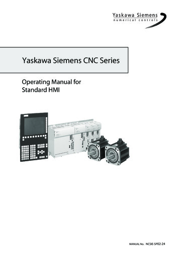
Reamers
Trepanning Trepanning produces a hole without reducing all of the removedmaterial into chips Trepanning can produce disks up to 150 mm (6 inches) diameter fromflat sheet or plates Trepanning can also be used to produce grooves for O-rings
Cutting Screw Threads Threads may be right-handed or left-handed, straight or tapered Threads can be produced by forming (most), casting (withdimensional inaccuracy), or machining (thread cutting) Standard Nomenclature is in Figures 22.16 and 22.17
Screw Thread Considerations Designs should allow for termination of thread before they reach ashoulder or the bottom of a blind hole Eliminate shallow, blind tapped holes Use chamfers to minimize finlike threads with burrs Do not interrupt threads with slots, holes, or other discontinuities Use standard thread tooling and inserts when possible Thin-walled parts should have sufficient thickness and strength toresist clamping and cutting forces. A good rule of thumb is that theminimum engagement length of a fastener should be 1.5 times thediameter Design parts so that all cutting operations can be completed in onesetup
Tapping Produces internal screw threads in previously drilled or reamed holesA tap has two (most commonly), three, or four cutting teeth (flutes)Taps are usually made of carbon steel (light duty) or high-speed steels(heavy production)30-40% of machining operations in automotive manufacturing involvestapping holesChip removal and coolant delivery are important issuesDrilling and tapping with a single specialized tool is called drapping
Milling A rotating, multi-tooth cutter removesmaterial and produces multiple chips ina single revolutionCNC machining centers can performmultiple operations in a single setup
Milling MachinesFigure 23.15 Schematic illustration of a horizontalspindle column-and-knee type milling machine. Source:G. Boothroyd.Workholding is accomplished withfixtures, vises, or clamps, whichmay also be flexibleFigure 23.16 Schematic illustration of a vertical-spindlecolumn-and-knee type milling machine (also called a kneemiller). Source: G. Boothroyd.
Horizontal Milling MachinesPrimary motion is rotation of the cutting toolFeed motion is translation of the workpiece
Slab Milling In slab, or peripheral, milling the axis of cutter rotation in parallel to theworkpiece surface being machinedCutters may have straight or helical teeth, resulting in orthogonal or obliquecutting action, respectively (helical teeth lower tooth load, tool forces, chatter)In conventional (up milling) the maximum chip thickness is at the end of thecut, so tooth engagement does not depend upon workpiece surface quality orscaling, but clamping forces must be higher and chatter is harder to avoidIn climb (down milling) the cut starts with the maximum chip thickness buthigh impact forces can be a problem
Horizontal Milling Tools
Milling ParametersTABLE 23.1N f D n v V Rotational speed of the milling cutter, rpmFeed, mm/tooth or in./toothCutter diameter, mm or in.Undeformed chipNumber of teeth on cutterthickness forLinear speed of the workpiece or feed rate, mm/min or in./minstraight-toothcutterSurface speed of cutter, m/min or ft/min2 fd D N tc f Feed per tooth, mm/tooth or in/toothD v /N nl Length of cut, mm or in.t Cutting time, s or min ( l lc ) v , where lc extent of the cutter’s first contact with workpieceMRR mm3/min or in.3/min w d v , where w is the width of cutTorque N-m or lb-ft( Fc ) (D/2)Power kW or hp (Torque) ( ), where 2 N radians/minNote: The units given are those that are commonly used; however, appropriate units mustbe used in the formulas.
End and FaceMilling
Face Milling Cutters
Face Milling In face milling the axisof cutter rotation isperpendicular to theworkpiece surfaceCutterdiameterto width ofcut ratioD:w 3:2A face-milling cutter with indexable inserts.Source: Courtesy of Ingersoll Cutting Tool Co.Face-milling operation showing (a) action of an insert in face milling; (b) climb milling;(c) conventional milling; (d) dimensions in face milling. The width of cut, w, is notnecessarily the same as the cutter radius. Source: Ingersoll Cutting Tool Co.
Face Milling Feed Marks and Chatter Face milling leaves feed marks on the surface of the workpieceFeed marks can lead to chatter in subsequent cutsChatter is self-excited vibrationDue to surface variations, cutting forces vary andthe tool vibrates in a regenerative mannerFigure 23.7 Schematic illustration of the effect of insert shape on feed marks on a face-milled surface: (a) smallcorner radius, (b) corner flat on insert, and (c) wiper, consisting of a small radius followed by a large radius whichleaves smoother feed marks. Source: Kennametal Inc. (d) Feed marks due to various insert shapes.
Milling Considerations Use standard milling cutters Use chamfers instead of radii Avoid internal cavities and pockets because cutters have a finite edgeradius Stiff workpieces minimize deflections from clamping or cutting forces Mount cutters as close to the spindle base as possible to reduce tooldeflections and avoid chatter and vibration Use rigid tool holders and fixturing In case of chatter, change tool shape and process conditions, or usecutters with fewer teeth or random spacing
Troubleshooting Milling OperationsTABLE 23.5ProblemTool breakageTool wear excessiveRough surface finishTolerances too broadWorkpiece surfaceburnishedBack strikingChatter marksBurr formationBreakoutProbable causesTool material lacks toughness; improper tool angles; cuttingparameters too high.Cutting parameters too high; improper tool material; improper toolangles; improper cutting fluid.Feed too high; spindle speed too low; too few teeth on cutter; toolchipped or worn; built-up edge; vibration and chatter.Lack of spindle stiffness; excessive temperature rise; dull tool; chipsclogging cutter.Dull tool; depth of cut too low; radial relief angle too small.Dull cutting tools; cutter spindle tilt; negative tool angles.Insufficient stiffness of system; external vibrations; feed, depth, andwidth of cut too large.Dull cutting edges or too much honing; incorrect angle of entry orexit; feed and depth of cut too high; incorrect insert geometry.Lead angle too low; incorrect cutting edge geometry; incorrect angleof entry or exit; feed and depth of cut too high.
Gear Manufacturing Gears can be manufactured by casting, forging, extrusion, drawing,thread rolling, and powder metallurgy Blanking sheet metal can be used to make thin gears for watches orclocks Plastic gearscan be madeby injectionmolding orcasting Machininggears isaccomplishedby geargenerating orform cuttingNomenclature for an involute spur gear.
Gear Form Cutting and Generating Form cutting is accomplished with a shaped milling cutter or broach Generating is done with a hob, or pinion- or rack-shaped cutters(a) Producinggear teeth on ablank by formcutting. (b)Schematicillustration ofgear generatingwith a pinionshaped gearcutter. (c)Schematicillustration ofgear generatingin a gear shaperusing a pinionshaped cutter.Note that thecutterreciprocatesvertically. (d)Gear generatingwith rackshaped cutter.
CNC Lathe with Turrets (a) (b) Figure 22.11 (a) A turret with six different tools for inside-diameter and outside-diameter cutting and threading operations. (b) A turret with eight different cutting tool