Transcription
NOVYI MIR Research JournalISSN No: 0130-7673Dynamic Analysis of Hybrid Tall Tube Structural systemPavithra S E1, Dr. S Vijaya2, Kavya H K312PG student in Structural Engineering, Dr. AIT, Bengaluru, Karnataka, IndiaProfessor, Department of Civil Engineering, Dr. AIT, Bengaluru, Karnataka,India3Assistant Professor, Department of Civil Engineering, Dr. AIT, Bengaluru,Karnataka, IndiaAbstract: Now a days there is need for multi-storied building due toovercrowding of cities.Multi-storied buildings are used for office, complex,residential flats, public centers etc. These multistoried buildings can betransformed into tall buildings in order to achieve more floors space but occupyless land space. Over the past few years tubular structures are becoming acommon feature in tall buildings. Tube structures are particularly suitable for alltall buildings. In the design of tall buildings, lateral loads play predominant role.The lateral loads are wind load and seismic load. They are analyzed in Etabs 2017.The analysis is carried out using Equivalent static method and response spectrummethod. The analysis is performed for seismic zone III and medium soil type.Results are tabulated and corresponding graphs are plotted.Key words: High rise buildings, Seismic analysis, Response spectrum method,Equivalent static method, Tube structure, Etabs.1. IntroductionIn the recent times the design process of high-rise structure has updated. The 3Dmodelling of building has better than previous due to technological advancementand excellent graphical software’s available in the market. The software captureshuge results and data. It also shows the failure modes in better views. It is alsovery important that the user should have sufficient technical knowledge andhaving judging capacity on the results obtained. The Finite Element results haveshown that the accuracy in the results. This also avoids the disagreement betweenengineers for same building.Tube systemsThe various forms of tube structural systems are as listed belowFramed Tube systemFor framed tube structures the lateral resistance is given by very stiff momentresisting frames that form a tube around the perimeter of the building. Theframes consist of closely spaced columns, 2–4 meters between centres,connected by girders. The tube carries all the lateral load and the self-weight isdistributed between the outer tube and the interior columns or walls.Volume 5, Issue 12, 2020Page No: 47
NOVYI MIR Research JournalISSN No: 0130-7673Bundled tubeThe bundled tube structure consists of four parallel rigid frames in eachorthogonal direction, interconnected to form nine bundled tubes. The principleis the same as for the single tube structure where the frames in the horizontalload direction acts as webs and the perpendicular frames acts as flanges.Tube in Tube SystemWhat differentiates the tube in tube concept from other structural systems isthat an outer framed tube (hull), is working together with an internal tube(core), usually elevator shafts and stairs, to resist both the lateral and verticalloading. This provides increased lateral stiffness and can be seen as the shearand flexural components of a wall-frame structure.Hybrid SystemA hybrid system is often used where the building design has a slendernesssuch that a single system cannot provide adequate strength or stiffness. Itcombines two or more basic structural forms, either by direct combination orby adopting different forms in different parts of the structure. As high-risebuilding designs become more complex, hybrid systems are increasinglycommon.2. ObjectivesThe following objectives are considered in the present studies. To understand the behaviour of super tall structure and theirimportance in resisting the lateral loads. To understand the behaviour of Bundled tube structures and tube intube structures. To study the effect of hybrid tubular forms over bundle tube structureswhich are subjected to earthquakes. Understanding the behaviour of all these structures subjected to staticand dynamic analysis.3. MethodologyNow a days there is need for multi-storied building due to overcrowding ofcities.Multi-storied buildings are used for office, complex, residential flats, publiccenters etc. These multistoried buildings can be transformed into tall buildings inorder to achieve more floors space but occupy less land space.Over the past few years tubular structures are becoming a common feature in tallbuildings. Tube structures are particularly suitable for all tall buildings. In thedesign of tall buildings, lateral loads play predominant role. The lateral loads arewind load and seismic load.The following models are considered for the study.1. RCC Framed structure2. Simple tube structure3. Tube in tube structural systemVolume 5, Issue 12, 2020Page No: 48
NOVYI MIR Research JournalISSN No: 0130-76734. Bundled tube system5. Hybrid structureThey are analyzed in Etabs 2017. The analysis is carried out using Equivalentstatic method and response spectrum method. The analysis is performed forseismic zone III and medium soil type. Results are tabulated andcorresponding graphs are plotted.3.1 Model descriptionThe below table 3.1 represents the structural details of the models considered inthe study.Table 3.1-Material Properties and Design ParametersSl. No.DescriptionData1.Seismic ZoneIII2.Seismic Zone Factor (Z)0.163.Importance Factor (I)1.54.Response Reduction Factor (R)55.Damping Ratio0.056.Soil TypeMedium Soil (Type III)7.Height of the building150m (50 Storey)8.Story to story Height3.0 m9.Span Length6m10.Column usedRCC and Steel Column11.Thickness of Slab200 mm12.Floor Finish1.5 KN/m213.Live Load4.0 KN/m214.Grade of Concrete (fck)M6015.Grade of Structural Steel (fys)Fe 35016.Grade of Reinforcing Steel (fyr)Fe 5004. Results and DiscussionThe various models explained in the previous chapters are analysed. The resultsare extracted and tabulated here. The discussions are carried out with the help ofgraphs.Volume 5, Issue 12, 2020Page No: 49
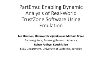
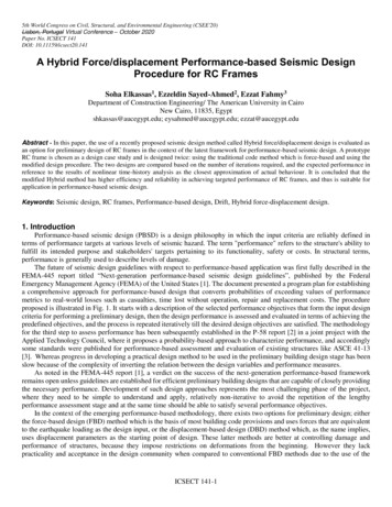
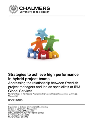
NOVYI MIR Research JournalISSN No: 0130-76734.1. Equivalent Static Analysis:4.1.1 DisplacementFigure 4.1 Displacement vs Storey EQXFigure 4.1 shows the graph of displacement versus storey of equivalent staticanalysis. From the above graph it is observed that, the model 5 (hybrid structure)is having very high displacement (448mm) compared to other models. It is alsoobserved that the model 3, which is Tube in Tube structure is having lessdisplacement and the other models having minimum displacement. However, themodel 5 displacement is increasing from storey 25 onwards. This is due to steelstructure commencing from that level. The displacement of steel structure is highcomparatively and the model 3 (Tube in Tube structure) proved to be more rigidstructure and hence lesser displacement of 112mm because of its stiffness.4.1.2. DriftFigure 4.2 Drift vs Storey EQXVolume 5, Issue 12, 2020Page No: 50
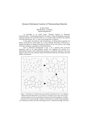
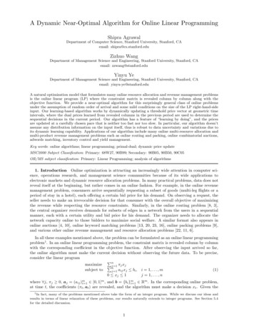
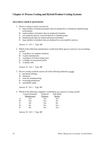
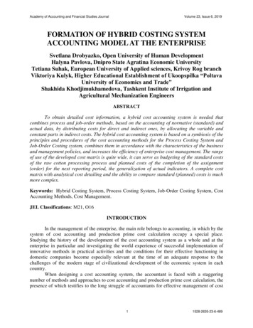
NOVYI MIR Research JournalISSN No: 0130-7673Figure 4.2 shows the graph of drift versus storey by equivalent static analysis. Thegraph shows that the model 1 (RCC Framed structure), model 2 (Simple Tubestructure), model 3 (Tube in Tube structure), and the model 4 (Bundled Tubestructure) is having the drift limits with in the allowable range. However, themodel 5 up to 25th level i.e., till RCC portion is seems ok. But the steel structure ispossessing highest level of drift than the allowable and hence drift shall becontrolled by external bracing or other lateral load resisting system.4.1.3. Base ShearFigure 4.4 shows the graph of base shear values for all models. The model 4,which is Bundled structure is having lesser base shear than other models due to itsless total built up area and hence lesser load. The other models have minorvariations among base shear. However, if we compare with regular sized models,the model 5 (Hybrid model) is having very less base shear than other models andhence the seismic forces acts on the structure is also less.Figure 4.3 Base Shear EQX4.2. Response Spectrum Analysis:4.2.1. DisplacementFigure 4.4 shows the graph of displacement versus storey by response spectrumanalysis. In the graph above, it is shown that the model 5 (Hybrid structure) ishaving more displacement of 362mm than other models and the model 4 (Bundledstructure) is having lesser displacement of 85mm. However the model 5 at steelportion is possessing more displacement then RCC portion in the same model.This is due to increase in flexibility in steel structure than RCC. The model 4 isVolume 5, Issue 12, 2020Page No: 51
NOVYI MIR Research JournalISSN No: 0130-7673having lesser displacement than any other models because it is rigid structure,since it is having higher stiffness than other models.Figure 4.4 Displacement vs Storey SPECX4.2.2. DriftFigure 4.5 shows the graph of drift versus storey by Response spectrum analysis.The graph shows that all structure is having the drift limits with in the allowablerange. However, the model 5 up to 25th level i.e., till RCC portion is seems ok.But the steel structure is possessing highest level of drift than the allowable andhence drift shall be controlled by external bracing or other lateral load resistingsystem.Figure 4.5 Drift vs Storey SPECXVolume 5, Issue 12, 2020Page No: 52
NOVYI MIR Research JournalISSN No: 0130-76734.3. Modal Analysis4.3.1. Time PeriodFigure 4.6 shows the graph of time period versus modes. It is observed that, themodel 5, hybrid model is having higher flexibility than any other type of RCCmodel. And hence the higher time period of 13.6sec, this is because of steelstructure commencing from the 25 storey onwards. However, the model 1 possessgreater flexibility in the RCC type of model and its time period is 6.2sec. Themodel 4, which is Bundled Tube structure is more rigid than other models andhence the lesser time period of 3.3sec, this is because of its stiffness.Figure 4.6 Time Period vs Modes5.Conclusion The displacement in dynamic analysis is lesser than static analysis. Thereduction in displacement is found to be 19.6%. The static analysis results show higher responses than dynamic analysis.This will escalate the construction cost by some percentage. The stiffness of the model 3 is found to be more since, it is having lesserdisplacement values. But even though displacement in model 4 is stilllesser but the plan area is lesser and hence lesser displacing. The Model 4, i.e., bundled tube structure is having very less displacementcompared to all other models. This proves that this model is having higheststiffness comparatively.Volume 5, Issue 12, 2020Page No: 53
NOVYI MIR Research JournalISSN No: 0130-7673REFERENCES Criteria for earthquake resistant design of structures IS 1893 (Part 1):2002.IS 875 Part 1 1987 “unit weight of materials”.IS 456 code of practice for plain and RC Concrete.Shubham Shukla (2020), “An Interpretation of Seismic behaviour of Tubein Tube building and moment resisting building” ISSN: 2278-3075,Volume 9, Issue 9.Suraj R Wadagule (2019), “Comparative Study of Tube in Tube Structureand Frame Tube Structure” ISSN: 2395-0056, Volume 6, Issue 7.Chinmayee Kulkarni (2019), “Analysis of tubular structure in high risebuildings” ISSN: 2230-9926, Volume 9, Issue 4.Mohammad Tabrez Shadulla1, Kiran K M2 (2018), “Analysis of tube intube structures with different size of inner tube” ISSN: 2455-2585, Volume4, Issue 10.Subathra Kannan (2018), “Seismic Behaviour of RCC Framed TubeStructure” ISSN: 2455-9288, Volume 3, Issue 1.Hardik J. Patel1, Prof. A.R.Darji 2, Prof Dr. K.B. Parikh (2016),“Parametric study on braced tube structural system” ISSN: 2349-5162,Volume 3, Issue 6.Nimmy Dileep1, Renjith R2 (2015), “Analytical Investigation on thePerformance of Tube-In-Tube Structures Subjected to Lateral Loads”ISSN: 2320-8163, Volume 3, Issue 4.Ray P. S. Han (1989), “Analysis of framed tube structures of arbitrary.”Volume 13.Volume 5, Issue 12, 2020Page No: 54
Bundled tube The bundled tube structure consists of four parallel rigid frames in each orthogonal direction, interconnected to form nine bundled tubes. The principle is the same as for the single tube structure where the frames in the horizontal load direction acts as webs and the perpendicular frames acts as flanges. Tube in Tube System What differentiates the tube in tube concept from other .