Transcription
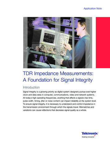
Application NoteTDR Impedance Measurements:A Foundation for Signal IntegrityIntroductionSignal integrity is a growing priority as digital system designers pursue ever-higherclock and data rates in computer, communications, video and network systems.At today s high operating frequencies, anything that affects a signal s rise time,pulse width, timing, jitter or noise content can impact reliability at the system level.To ensure signal integrity, it is necessary to understand and control impedance inthe transmission environment through which the signals travel. Mismatches andvariations can cause reflections that decrease signal quality as a whole.
Using TDR to Help Solve Signal Integrity IssuesApplication NoteImpedance tolerances are part of the electrical specificationsfor many of today’s digital system components, includingFirewire, PCIe, SATA, DisplayPort and more. It is standardpractice to use modeling tools to design high-speed circuits.Modeling hastens the design cycle and minimizes errors.However, modeled designs must be verified with hardwaremeasurements, including impedance measurements, after theprototype is built.The methodology of choice for measuring impedances isTime Domain Reflectometry (TDR), carried out using highperformance instruments such as the DSA8200 oscilloscopeequipped with the 80E04 TDR sampling module. TDR permitsthe signal transmission environment to be analyzed in the timedomain just as the signal integrity of data signals is analyzedin time domain.What is Time Domain Reflectometry?Time Domain Reflectometry (TDR) measures the reflectionsthat result from a signal travelling through a transmissionenvironment of some kind – a circuit board trace, a cable,a connector and so on. The TDR instrument sends a pulsethrough the medium and compares the reflections from theunknown transmission environment to those produced by astandard impedance. A simplified TDR measurement blockdiagram is shown in Figure 1.StepSourceSMAConnectorTo OscilloscopeMainframeThe mathematical foundation of TDR measurements iselementary but important. Fundamentally, TDR measurements are based on a series of impedance ratios. Most TDRinstruments will perform the necessary ratio calculationsinternally and display a numerical result.TDR measurements are described in terms of a ReflectionCoefficient, ρ (rho). The coefficient ρ is the ratio of thereflected pulse amplitude to the incident pulse amplitude:ρ ρ SamplerTDR Sampling ModuleFigure 1. Block diagram of TDR circuitThe TDR display is the voltage waveform that returns when afast step signal is propagated down a transmission line. Theresulting waveform is the combination of the incident step andreflections generated when the step encounters s(ZL - Z0)(ZL Z0) When ZL is equal to ZO, the load is matched. Vreflected, thereflected wave, is equal to 0 and ρ is 0. There are no reflections:Vreflected Vincident0V 0A ZL reading of zero (0) implies a short circuit. The reflectedwave is equal to the incident wave, but opposite in polarity.As seen below, the reflected wave negates part of the incidentwave. The ρ value is —1.ρ Vreflected Vincident-VV -1When ZL is infinite, an open circuit is implied. The reflectedwave is equal to the incident wave and of the same polarity.As seen below, the reflected wave reinforces part of theincident wave. The ρ value is 1.ρ 2VreflectedVincidentNow that we have the formulas, if we plug in numbersrepresenting a matched load, a short circuit and an openload, we can see that ρ has a range of values from 1 to —1,with 0 representing a matched load.Z LoadZ0VreflectedVincidentFor a fixed termination ZL, ρ can also be expressed in terms ofthe transmission line characteristic impedance, ZO and theload impedance ZL.ρ Transmission Line50 ΩThe Reflection Coefficient: Doing the MathVreflected VincidentVV 1
Using TDR to Help Solve Signal Integrity IssuesApplication NoteFigure 2 is an actual TDR display from a Tektronix Samplingoscilloscope. The traces clearly illustrate the math conceptssummarized above.Units itShortCircuitUnits of Time - Sec/DivFigure 3. Simplified diagram of a TDR waveformOther lumped and distributed effects can be observed andcharacterized with TDR techniques. Figures 4 through 8 illustrate idealized TDR results obtained with diverse types ofimpedance and terminations.– Short Circuit TerminationTP2TPVZ0ZL 00Figure 2. Time domain measurement shows a step with an open and a short circuit.The short circuit is measured as —1 ρ (rho) and the opencircuit (infinite ohms) results in a ρ of 1.– Open Circuit TerminationTP2V2TPVCalculating the Impedance of the TransmissionLine and the LoadThe characteristic impedance Z0, or the load impedance ZL,can be calculated with the value of ρ.ZL ZO *(1 ρ)(1-ρ)Z0ZL OpenZ0ZL Z0oFigure 4. Short and open circuit terminations– Matched Load TerminationTP2TPWith most of today’s TDR-capable instruments, such as theTektronix sampling oscilloscope, TDR measurements can bedisplayed with units of volts, ohms, or ρ (rho) on the verticalmagnitude scale. The horizontal axis represents units of time,as shown in Figure 3.V0– Mismatched Load TerminationTPV VRZL Z02TPVoZ0ZL Z0ZL Z0Figure 5. Matched and mismatched load terminationswww.tektronix.com/oscilloscopes3
Using TDR to Help Solve Signal Integrity IssuesApplication NoteLooking at Real-World Circuit Characteristics– Capacitor Load TerminationTPTypically, etched circuit boards have impedance-controlledmicrostrip and stripline transmission lines. Over the span ofthese transmission lines, components, vias, connectors andother “interruptions” create impedance discontinuities. Thesediscontinuities can be modeled as inductors, capacitors andtransmission lines.2V2TPVZ0ZL C0– Inductor Load TerminationTP2TPVZ0ZL LThe TDR waveform shows the effect of all the reflectionscreated by all of the impedance discontinuities, as shown inFigure 9. The waveform is like a road map of the impedancevariations across the trace. Now the waveform can beevaluated to determine how much the impedance deviatesfrom the nominal value. Some TDR-capable instruments,such as the DSA8200 oscilloscope and 80E04 TDR samplingmodule, offer extended math functions that can calculateactual component values and the physical distance to pointsof interest along the transmission line.oFigure 6. Capacitive and inductive load terminations– Shunt Capcitance DiscontinuityTP2TPVZ0Z0C0In Figure 9, the waveform is the result of an ideal pulsetraveling through a transmission medium. A TDR samplingmodule such as the 80E04 produces a very accurate,controlled pulse with a fast rise time and minimal aberrations.Imagine sending a typical data waveform down the sametransmission path! The data pulse’s own aberrations wouldinteract with the discontinuities in unpredictable ways. It’s asituation that lends itself to erratic, intermittent problems.Characterizing the environment with TDR measurements(and then correcting the discontinuities) can improve signalintegrity significantly.– Series Inductance DiscontinuityTP2TPVZ0Z0oFigure 7. Capacitive and inductive discontinuities– Series Inductance – Shunt ductiveDiscontinuityZ0Z0– Shunt Capcitance – Series InductanceZTP2TPVZ2Z1100Z0Ct2t1Z0oZ2Z1Figure 8. Mixed capacitive and inductive loadingincidentCeq t12Z1Leq Z 2t 220TimeFigure 9. The TDR waveform reveals trace discontinuities4www.tektronix.com/oscilloscopes
Using TDR to Help Solve Signal Integrity IssuesApplication NoteTDR Resolution FactorsSettling AberrationsWe have established that TDR measurements can produceuseful insights into circuit impedance and signal integrity. Butall TDR solutions are not created equal. Several factors affecta TDR system s ability to resolve closely-spaced discontinuities.Aberrations, such as ringing, that occur after the incidentstep (Figure 10) will cause corresponding aberrations in thereflections. These aberrations will be difficult to distinguishfrom the reflections caused by discontinuities in the deviceunder-test (DUT). Note that aberrations in the TDRinstrument’s step generator and aberrations in the stepresponse of its sampler have virtually the same effect.If a TDR system has insufficient resolution, small or closelyspaced discontinuities may be smoothed together into asingle aberration in the waveform. This effect may not onlyobscure some discontinuities, but it also may lead toinaccurate impedance readings. Rise time, settling timeand pulse aberrations can also significantly affect aTDR system s resolution.Rise TimeA reflection from an impedance discontinuity has rise timeequal to or–more likely–longer (slower) than that of theincident step. The physical spacing of any two discontinuitiesin the circuit determines how closely their reflections will bepositioned relative to one another on the TDR waveform. Twoneighboring discontinuities may be indistinguishable to themeasurement instrument if the distance between themamounts to less than half the system rise time. The equationbelow summarizes this concept.T(resolution) 1/2 TR(system)Pre - aberrationsAberrations that occur prior to the main incident step canbe particularly troublesome because they arrive at a discontinuity and begin generating reflections before the main steparrives. These early reflections reduce resolution by obscuringclosely-spaced discontinuities.Figure 10. Diagram of aberration effects on a TDR pulseTDR Accuracy FactorsMany factors contribute to the accuracy of a TDR measurement. These include the TDR system’s step response,interconnect reflections and DUT losses, step amplitudeaccuracy, baseline correction and the accuracy of thereference impedance (ZO) used in the measurements.Reference ImpedanceAll TDR measurements are relative; they are made bycomparing reflected amplitudes to an incident amplitude.Modern TDR instruments perform all of the calculations tocompare the incident and reflected amplitudes and show theresults directly in rho or ohms. However, the process is stilldependent on the accuracy of the reference impedance (ZO).For TDR applications, the Tektronix oscilloscope uses a highprecision 3.5 mm air line connector as a stable impedancereference for the calculation of rho and ohms. Connectorimpedance is measured relative to an external, traceable,precision air line during module calibration.www.tektronix.com/oscilloscopes5
Using TDR to Help Solve Signal Integrity IssuesApplication NoteStep Amplitude and Baseline CorrectionInterconnect Accuracy and ReflectionsIn general, modern TDR instruments measure and/or calibratethe incident step amplitude and, given the known stepamplitude and baseline level, compute millirho and ohms.The Tektronix oscilloscope goes one step further by placing aknown air line in the sampling module. It then monitors thebaseline and incident step amplitude periodically. Thus, thesystem is automatically compensated, allowing for veryrepeatable measurements even if the step amplitudeoffset drifts.If a long probe cable is used, it is prudent to measure theDUT impedance relative to the end of the cable in order toreduce the effect of cable loss. However, in this case, theimpedance of the cable directly affects the accuracy of themeasurement. The reference level will be shifted by the rho ofthe cable (ρcable) and the step amplitude incident on the DUTwill be (1- ρcable ). For maximum accuracy, these parameterscan be measured and their impedance calculated.Incident Step AberrationsThe most obvious problem caused by incident step aberrations is that the reflected step amplitude cannot be measuredaccurately, if the pulse does not settle in a time that is shortrelative to the line being measured. This type of error is onlyimportant for a DUT impedance that is significantly differentthan 50 ohms. In such a case, accuracy is highly dependenton the reflected step amplitude accuracy. Closer to 50 ohms,accuracy is more dependent on the reference impedancesince reflections are very small.A second type of aberration that can cause problems is the“foot” or pre-shoot that precedes the step. If the DUT has anopen circuit at the end, this part of the step will reflect off theopen circuit before the obvious rising edge of the step is inview. This will cause an error near the end of the linebeing measured.A more subtle effect is caused by the low frequency stepaberrations. These aberrations can appear as a slope in thetrace even with a perfect 50 ohm termination in place of theDUT. This causes an offset in the 50 ohm level if the DUT isnot measured in the same time period in which the referenceimpedance was measured.NoiseRandom noise can be a significant source of error whenmaking measurements of small impedance variations.Fortunately, modern instruments can perform signal averagingto reduce the effects of random noise. The drawback in manyinstruments is that averaging can dramatically slow theprocessing speed, particularly if automatic measurements arebeing displayed. The Tektronix oscilloscope addresses thisproblem with its built-in multiple processors, which can sharethe processing ns from interconnect components and the probe-toDUT interface can also cause problems. The probe interfacecan create a large inductive reflection that must settle beforean accurate measurement can be made. It is extremelyimportant to keep the probe tip and ground leads short tominimize these problems.Cable LossesCable losses in the test setup can cause several problems.While both conductor loss and dielectric loss can occur,conductor loss usually dominates. Conductor loss is causedby the finite resistance of the metal conductors in the cablewhich, due to the skin effect, increases with frequency. Theresult of this incremental series resistance is an apparentincrease in impedance as you look further into the cable.So, with long test cables, the DUT impedance looks higherthan it actually is.The second problem is that the rise time and settling of theincident pulse is degraded by the time it reaches the end ofthe cable. This affects resolution and accuracy since theeffective amplitude of the incident step is different thanexpected. This amplitude inaccuracy does not cause mucherror when the DUT impedance is close to 50 ohms, but for alarger or smaller impedance, the error can be significant.
Using TDR to Help Solve Signal Integrity IssuesApplication NoteConductor loss can be minimized by using an extender cableto bring the sampling head closer to the DUT. If this is notpossible, methods such as the Comparative Reflectiontechnique can help resolve the issue. An example of thistechnique is as follows:Substitute an air line of known standard impedance for theDUT. Measure the actual impedance reading with this airline in place. This measurement provides an offset valuethat is used in the next step. The offset value quantifies theeffect of the interconnect elements preceding the DUT.Add or subtract the offset value from all subsequentmeasurements on the DUT itself.The excellent linearity of TDR-capable instruments such asthe DSA8200 oscilloscope ensures that the step signalexperiences identical source, interconnect and samplerimperfections with either the standard or the DUT present.The comparative reflection greatly improves the absoluteaccuracy of ρ and impedance measurements.Controlling Rise TimeWhile in many cases the fastest rise time available is desirable, very fast rise times can, in some cases, give misleadingresults on a TDR measurement. For example, testing theimpedance of a microstrip on a circuit board with a 35 ps risetime system provides excellent resolution. However, even thehighest speed logic families in use today cannot begin tomatch the 35 ps rise time of the TDR step. Typical high-speedlogic families such as ECL have output rise times in the 200ps to 2 ns range. Reflections from small discontinuities suchas stubs or sharp corners in the microstrip will be quite visibleand may generate large reflections at 35 ps rise time. Thesame transmission line driven in actual operation by an ECLgate with a 1 ns rise time may produce negligible reflections.This difference between measurement and reality could bethe beginning of a signal integrity problem. In attempting tocorrect the misleading impedance readings, you mightcompromise the environment that the real operational signalsneed. It is often preferable to see the transmission line s TDRresponse to rise times similar to the actual circuit operation.Some TDR instruments provide a means of increasing theapparent rise time of the incident step. The Tektronix samplingoscilloscope implements filtering using a double-boxcaraveraging technique, that is equivalent to convolving thewaveform with a triangular pulse. The filtering is performedusing live waveform math to show the filtered response innear real time. This technique provides fully “live” filteredwaveforms, quickly responds to changes, and requires noadditional calibration steps. The filtered waveform resultcorresponds very well with similar measurements made withan equivalent pulse from an external generator.Differential TDR MeasurementsMany high-speed designs are implemented with differentialtransmission lines. This approach offers many advantages,but does not eliminate the need to make TDR measurementsto support signal integrity.All of the single-ended TDR measurement concepts discussedso far also apply to differential transmission lines. However,they must be extended to provide useful measurements ofdifferential impedance.A differential transmission line has two unique modes ofpropagation, each with its own characteristic impedance andpropagation velocity. Much of the literature refers to these asthe odd mode and the even mode.The odd mode impedance is defined as the impedancemeasured by observing one line, while the other line isdriven by a complementary signal.The differential impedance is the impedance measuredacross the two lines with the pair driven differentially.Differential impedance is twice the odd mode impedance.The even mode impedance is defined as the impedancemeasured by observing one line, while the other line isdriven by an equivalent signal as the first.The common mode impedance is the impedance of thelines connected together in parallel, which is half the evenmode impedance.www.tektronix.com/oscilloscopes7
Using TDR to Help Solve Signal Integrity IssuesApplication NoteTying together the two conductors in a differential line anddriving them with a traditional single-ended TDR system,will yield a good measure of common mode impedance.However, common mode impedance is often less importantthan the differential impedance.To provide true differential impedance measurements, the80E04 TDR sampling module provides a polarity-selectableTDR step for each of two channels. With this approach, thedifferential system can actually be driven differentially, just as itwill when the DUT is functioning in its intended application.The response of each side of the differential line is separatelyacquired and evaluated as a differential quantity.Both sampler channels must have matched step response.The two steps must also be matched but complementary andthe steps must be time-aligned at the DUT. The Tektronixoscilloscope meets these requirements by incorporating twoacquisition and polarity-selectable TDR channels in a singlesampling module containing a common clock source. Therelative timing of the two step generators can be deskewedto precisely align the two steps at the DUT and remove anymismatch due to cabling.With the TDR system set up with complementary incidentsteps, and using ohms units, adding the two channels yieldsthe differential impedance. The individual traces give the oddmode impedance. If the line is not balanced, the two traceswill not exactly match.Deskewing the Step GeneratorsTrue differential TDR measurements require that both the stimulus and the acquisition systems be well matched in terms oftiming and step response. The step response is fixed by the design of the system. The relative timing of the two channels,however, is usually adjustable. Both the acquisition timing and the TDR step timing must match to yield a valid TDRmeasurement. Notice, however, that the matching requirement lies at the DUT rather than the front panel of the instrument.Poor matching between the cables or interconnect devices and the DUT will skew the TDR steps in time when they arriveat the DUT, even if they are aligned at the instrument’s front panel, causing significant measurement error.The most efficient way to eliminate or reduce this problem is to minimize the interconnect length and use carefully matchedcables. In the DSA8200 oscilloscope, the sampling head can be extended up to 2 meters from the mainframe without anyperformance penalty. This helps minimize cable lengths with associated mismatch, loss, dispersion and other errors.Deskewing of the acquisition paths is also very important, and in the DSA8200 oscilloscope, the timing of the stepgenerators can also be skewed, relative to each other using the deskew control in the TDR setup menu. Setting the timingof the step generators by looking at the TDR response from the two channels can be difficult; the correct setting is notalways obvious. However, the imbalance trace shows the effect of this timing mismatch in real time. Watching theimbalance trace makes adjusting the timing simple, since it displays the effects of the mismatch in real time.This deskew operation is also important for the acquisition involved. In the DSA8200 oscilloscope, the two channels in onesampling module are inherently well matched because they are driven from a common clock source.8www.tektronix.com/oscilloscopes
Using TDR to Help Solve Signal Integrity IssuesApplication NoteStatic Discharge PrecautionsHigh-bandwidth sampling heads are extremely static-sensitive.To ensure their continued performance in impedance andsignal integrity applications, they require protection devicesabove and beyond those which suffice for conventionaloscilloscopes. The following guidelines are essential whenhandling or using any high-bandwidth sampling module.Cap sampling inputs when not in use.Use grounded wrist straps of 10 meg ohms when incontact with the module.To prevent the possibility of probing a device that mayhave built up a charge, you should always discharge thedevice before probing or connecting it to the module. Youcan accomplish this by touching the probe ground lead oryour finger (assuming you are using a wrist strap) to thepoint you want to TDR test. The SIU800 Static IsolationUnit uses a microwave relay to perform this function. Withthis unit, the DUT cable is connected to ground until a footswitch is depressed and the relay switches, connecting theDUT to the TDR input.Probing and Interface AlternativesThe electrical interface from the coaxial 50 ohm cable environment to a circuit board microstrip can produce a localizeddisturbance in the ideal 50 ohm path to the tested device. It isdesirable to make this disturbance as small as possible, butcost and convenience are also considerations. Here are somecommonly used alternatives:P6150 Probe and Tip FittingsThe P6150 probe is used by many manufacturers because ofits convenience and off-the-shelf availability. This probe canbe specified as a standard, repeatable part of a test station.The 50 ohm probe cable is constructed of an unusuallyflexible material.SMA Board LaunchesAvailable from coax houses.Must be designed into and installed on the circuit board.Best interface for quality and repeatability.Best for high-frequency testing.Repeatability IssuesAn important part of measurement accuracy is repeatability. Ameasurement made of the same part at different times shouldyield the same result. Although this repeatability does notguarantee accuracy, accuracy will be impossible without it.There are several factors that affect repeatability.Probing and fixturing techniques and stability.Condition/quality of cables and connections.Measurement procedure.Instrument condition and calibration.Application Example: Making a Coupled TDRMeasurement on a USB DeviceBackgroundSignal integrity requirements have expanded with theincreased speed of USB. As a result, there has been anincreased interest in impedance measurements and theeffects of impedance variations within USB cables anddevices. A Tektronix sampling oscilloscope, equipped withan 80E04 sampling module, offers a versatile solution forimpedance measurements in support of signal integrity.A high-speed USB connection is made through a shielded,twisted pair (differential) cable with a characteristicimpedance ofZodd 45V (Zdiff 90V )615%Zeven 60V (Zcm 30V )630%and a maximum one-way delay of 26 ns (TFSCBL). The D and D- circuit board traces, which run between a transceiverand its associated connector, should also have a nominaldifferential impedance of 90 ohms.www.tektronix.com/oscilloscopes9
Using TDR to Help Solve Signal Integrity IssuesApplication NoteTDR Loading SpecificationThe AC loading specifications of a transceiver in thehigh-speed idle state are specified in terms of differential TDRmeasurements.These measurements govern the maximum allowabletransmission line discontinuities for the port connector, theinterconnect leading from the connector to the transceiver,the transceiver package, and the transceiver IC itself. In thespecial case of a high-speed-capable device with a captivecable, the transmission line discontinuities of the cableassembly are also governed.The following specifications must be met with the incident risetime of the differential TDR set to 400 ps. It is important tonote that all times are “as displayed” on the TDR and henceare “round trip times.”Termination impedance (ZHSTERM) is measured on the TDRtrace at a specific measurement time following the connectorreference time. The connector reference time is determined bydisconnecting the TDR connection from the port connectorand noting the time of the open circuit step. For an “A”connector, the measurement time is 8 ns after the connectorreference location.For a “B” connector, the measurement time is 4 ns after theconnector reference location. The differential terminationimpedance must be:80Ω ZHSTERM 100 ΩThrough impedance (ZHSTHRU) is the impedance measured from500 ps before the connector reference location until the timegoverned by the Termination impedance specification.70 Ω ZHSTHRU 110 ΩIn the Exception Window (a sliding 1.4 ns window insidethe Through Impedance time window), the differentialimpedance may exceed the Through limits. No singleexcursion, however, may exceed the Through limits for morethan twice the TDR step rise time (400 ps).10 www.tektronix.com/oscilloscopesIn the special case of a high-speed-capable device with acaptive cable, the same specifications must be met, but theTDR measurements must be made through the captive cableassembly. Determination of the connector reference time canbe more difficult in this case, since the cable may not bereadily removable from the port being tested. It is left to thetester of a specific device to determine the connectorreference location by whatever means are available.For more details about these TDR requirements and measurement conditions, see the Universal Serial Bus Specificationstandard, Revision 2.0.1The DSA8200 oscilloscope with the 80E04 sampling modulecan display both the individual positive and negative TDRwaveforms of a differential line. With this solution, the usercan view reflection characteristics and directly measure theimpedance of each conductor or the common mode of thedifferential line. This test system can also display the truedifferential measurements of both these lines and display themin ohms, providing the user with the required measurementsto validate any USB device.1. Universal Serial Bus 2.0 Specification, (www.usb.org/developers/usb20)
Using TDR to Help Solve Signal Integrity IssuesApplication NoteFigure 11. SMA fixture for TDR measurements on a USB 2.0-compliant component.USB 2.0 ImpedanceMeasurement ProcedureConnect the DUTThis connection can be accomplished with a breakout boardthat provides SMA connections on one end and a USBconnector on the other. The breakout board should have anSMA connector for each of the differential lines, as shownin Figure 11.Connect the other end of the SMA cables to an 80E0420-GHz TDR sampling module installed on the Tektronixoscilloscope. Be sure to follow strict static protectionprocedures when using any fast sampling module.Figure 12. TDR SETUP MenuTurn on TDR Waveforms and CreateDifferential Step PulsesIn the TDR Setup menu:Preset the channels that are associated. In this example itis Ch 3 and Ch 4, as shown in Figure 12.Select ohms (Ω) as the units to be displayed.Change the polarity of one of the channels to create adifferential step.You may also want to turn on Vectors in the Display menuand turn on Averaging from the Oscilloscope toolbar.Note that when you select negative polarity in the TDR menu,the stepgenerator produces a negative-going step. The samplingchannel is not inverted. Also notice that when the selectedunits are volts, you can see the step go negative, but with rhoand ohms units the step appears positive.To understand this concept, remember the definition of rho: itis the reflected voltage divided by the incident voltage and,therefore, is not dependent on the sign of the incident step.This also makes sense physically: the sign of the reflectioncoefficient is an indicator of an impedance larger or smallerthan the reference impedance, not a “negative impedance.”www.tektronix.com/oscilloscopes 11
Using TDR to Help Solve Signal Integrity IssuesApplication NoteFigure 13. Differential TDR traces before deskew adjustmentFigure 14. Differential TDR after
instruments will perform the necessary ratio calculations internally and display a numerical result. TDR measurements are described in terms of a Reflection Coefficient, ρ (rho). The coefficient ρ is the ratio of the reflected pulse amplitude to the incident pulse amplitude: For a fixed termination Z L, ρ can also be expressed in terms of