Transcription
RF / Microwave PC BoardDesign and LayoutRick HartleyL-3 Avionics Systemsrichard.hartley@L-3com.com1RF / Microwave Design - Contents1) Recommended Reading List2) Basics3) Line Types and Impedance4) Integral Components5) Layout Techniques / Strategies6) Power Bus7) Board Stack-Up8) Skin Effect and Loss Tangent9) Shields and Shielding10) PCB Materials, Fabrication and Assembly2
RF / Microwave - Reading ListPCB Designers – Transmission Line Design Handbook – Brian C. Wadell(Artech House Publishers) – ISBN 0-89006-436-9 HF Filter Design and Computer Simulation – Randall W.Rhea (Noble Publishing Corp.) – ISBN 1-884932-25-8 Partitioning for RF Design – Andy Kowalewski - PrintedCircuit Design Magazine, April, 2000. RF & Microwave Design Techniques for PCBs – Lawrence M.Burns - Proceedings, PCB Design Conference West, 2000.3RF / Microwave - Reading ListRF Design Engineers – Microstrip Lines and Slotlines – Gupta, Garg, Bahl and Bhartia.Artech House Publishers (1996) – ISBN 0-89006-766-X RF Circuit Design – Chris Bowick. Newnes Publishing (1982) –ISBN 0-7506-9946-9 Introduction to Radio Frequency Design – Wes Hayward. TheAmerican Radio Relay League Inc. (1994) – ISBN 0-87259-492-0 Practical Microwaves – Thomas S. Laverghetta. Prentice Hall, Inc.(1996) – ISBN 0-13-186875-64
RF / Microwave Design - BasicsRF and Microwave Layout encompassesthe Design of Analog Based Circuits in therange of Hundreds of Megahertz (MHz) toMany Gigahertz (GHz).) RF actually in the 500 MHz - 2 GHz Band.(Design Above 100 MHz considered RF.)) Microwave above 2 GHZ.)5RF / Microwave Design - BasicsUnlike Digital, Analog Signals can be atany Voltage and Current Level (Betweentheir Min & Max), at any point in Time.) Standard Analog Signals are assumed tobe between DC and a few Hundred MHz.) RF/Microwave Signals are One Frequencyor a Band of Frequencies imposed on aVery High Frequency Carrier.)6
RF / Microwave Design - BasicsRF/Microwave Circuits are Designed toPass Signals within Band of Interest andFilter Energy outside that Range.) Signal Band can be Narrow or Wide.)*Narrow Band Circuits usually have Pass Bandless than 1 MHz.* Broad Band Circuits Pass a Range of Frequencies up to 10’s of MHz.7RF / Microwave Design - Basics) WhenDigital and Microwave exist inthe Same Unit, Pass Bands of Microwave Circuits usually fall (by design)Outside the Harmonic Range of theDigital Signals.8
RF / Microwave Design - BasicsRF / Microwave PC Board Layout simplyfollows the “Laws of Physics”) When Laws of Physics can’t be followed,Know what Compromises are available.)THIS IS NOT BLACK MAGIC!!!9RF / Microwave Design - BasicsMicrowave Signals are Very Sensitive toNoise, Ringing and Reflections and Mustbe treated with Great Care.) Need Complete Impedance (Zo) Matching (50 ohm out/ 50 ohm line/ 50 ohm in).)*Minimizes Return Loss / VSWR.10
RF / Microwave Design - Basics)A Transmission Line is any Pair or Wires orConductors used to Move Energy From pointA to point B, Usually of Controlled Size andin a Controlled Dielectric to create a Controlled Impedance (Zo).11RF / Microwave Design - Basics)Inductance (L) is Determined by the LoopFunction of Signal and Return Path.*Small Spacing (Tight Loop) creates HighFlux Cancellation, hence Low Inductance.)Capacitance (C) is Function of Signal spacing to the Return Path.*Small Spacing creates High Capacitance.12
RF / Microwave Design - Basics)Since Small Spacing (Tight Loop) createsLow L & High C and since Zo sqrt L/C,Small Spacing creates Low Zo.)Additionally, Zo is function of Signal Conductor Width & Thickness and a Functionof the Dielectric Constant (ε r ) of the Material surrounding the Lines.13RF / Microwave Design - Basics)Sometimes Dielectric surrounding Transmission Line isn’t Constant (Outer LayerTrace on PCB).*DK above Trace is Air ( 1.0008).*DK below Trace is FR4 (approx 4.1).*Effective Relative ε r ( ε eff ) is 3 to 3.25.)Equations given later to Calculate EffectiveRelative ε r ( ε eff ).14
RF / Microwave Design - Basics)Signal Return Currents follow the Path ofLeast Impedance (In High Frequency Circuits that Path of Least Inductance).Whenever we Neglect to provide a LowImpedance Return Path for RF / Microwave signals, they WILL find a Path.) It may NOT be what we had in mind.)15RF / Microwave Design - Basics)Signal Wavelength *Wavelength (λ) of a Signal is the Distance itTravels in the Time of One Cycle.)For a Signal Traveling in Free Space *λ c (Speed of Light) / f (frequency).(λ 11.78”/nSec at 1GHz 11.78”))Signal in a Higher ε r Dielectric *λ c / f 1 / ε r16
RF / Microwave Design - Basics)Signal Critical Length*How long a PCB Trace can be before weMUST pay attention to Impedance Control.*Function of Frequency (1/16th Wavelength)Lcritical c11 fε eff 16At 1 GHz approx .425” (Microstrip- FR4)) At 1 GHz approx .375” (Stripline - FR4) 17)RF / Microwave Design - BasicsSignal Loss / Noise ) Reflections *Return Loss / VSWR)Skin Effect *Increased Resistance of PCB Trace due toDecreased Cross Sectional Area.*In Analog Circuits above 100 MHz.*Skin Depth- .000822” @ 10 MHz.000026” @ 10 GHz.18
RF / Microwave Design BasicsSignal Loss / Noise )Loss Tangent *Dielectric Loss caused by Molecular Structure of Board Material.*In Analog Circuits above 200 MHz.*PTFE’s Far Better than FR4.)Energy Coupling*Cross Talk.*Noise Induction.19RF / Microwave Design Line Types and Impedance (Zo))Waveguide*Uses Air as Transmisssion Mediumand Side Walls of Tube as Return Path.*Won’t Support Energy Propagation BelowCutoff Frequency.*Works Best at Ultra High Frequencies withMillimeter Wavelengths.20
RF / Microwave Design Line Types and Impedance (Zo))Waveguide *With an Air Dielectric, Signals Propagate atthe Speed of Light.*Very Low Loss due to Smooth Side Walls andthe Air Dielectric.*Ultra Low Loss with High Density, UltraSmooth Coating on Walls.*In Very High Power applications, Uses SolidDielectric to Prevent Voltage Arcing.21RF / Microwave Design Line Types and Impedance (Zo)Signal Traces Longer than Critical Length(1/16 λ in DK) Need Impedance Control toPrevent Return Loss due to Reflections.) Shorter Circuit Elements Don’t RequireImpedance Control, but it Usually does NOHarm.) Don’t bother to Zo Control Short Lines if itWill create a Problem (ie- DFM).)22
RF / Microwave Design Line Types and Impedance (Zo))Impedance (L/C)*Lower Er Materials Net Higher ImpedanceTraces and Faster Propagation Times per givenTrace Width & Trace-to-Ground Separation.*As Trace Width Increases, Trace ImpedanceDecreases (Thickness has Min Effect).*As Trace Spacing from Ground Increases,Impedance Increases.23RF / Microwave Design Line Types and Impedance (Zo)Transmission Line History ) Two Coplanar Strips in 1936. Later RolledUp to create Sealed Line.) Coax Lines during WWII.) Flat Stripline Using PCB Techniques rightafter WWII.) First use of Microstrip Reported in 1949.24
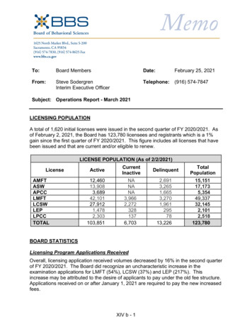
RF / Microwave Design Line Types and Impedance (Zo)Microstrip25RF / Microwave Design Line Types and Impedance (Zo)MicrostripZ0 120π4.0h 14.0 8.0 / ε r 4.0hln 1.0 11.0w' w'2.0 2.0π ε r 1.0 22 14.0 8.0 / ε r 4.0h 1.0 1.0 / ε r 2 π (Ω) 11.02.0 w' where: w' w w' 1 .0 1 .0 / ε r (Replace w' w 2 .0 4e w 1 .0 ln 2tπ 1/ π 2 (t / h ) w / t 1 .1 Erwith Eeff)26
RF / Microwave Design Line Types and Impedance (Zo)MicrostripZ0 60ε eff 8h w ln w 4h ifw 1hotherwiseZ0 120πε eff 1 w w 1.393 0.677 ln 1.444 h h27RF / Microwave Design Line Types and Impedance (Zo)Microstripε eff 2 wε 1 ε r 11 w 1 r 0.04 1 ifh22 12h h 1 w otherwiseε eff ε 1 ε 1 1rr 2 212h 1 w 28
RF / Microwave Design Line Types and Impedance (Zo)Embedded MicrostripMultiply Zo (from Microstrip) by -ε effε eff e ( 2.0 b / h ) ε r [1.0 e ( 2.0b / h ) ]Can use w/Soldermask over Microstrip (Often NOT Needed) 29RF / Microwave Design Line Types and Impedance (Zo)Centered Stripline30
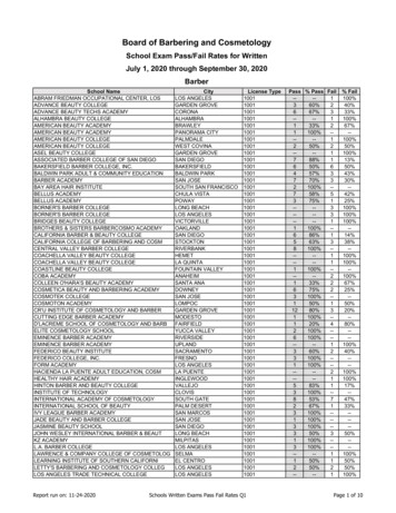
RF / Microwave Design Line Types and Impedance (Zo)Centered Stripline2 120π4 . 0 (b t ) 8 . 0 (b t ) 8.0(b t ) ln 1.0 Z0 6.27 π w' π w'2.0π ε r π w' where:b 2 .0 h t ww' w tt w 1.0 ln π t e 2m .25π 1 2.0(b t ) / t 1 w / t 1.1 31RF / Microwave Design Line Types and Impedance (Zo)Off-Center Stripline(Equations in Wadell- Pages 130-133)32
RF / Microwave Design Line Types and Impedance (Zo)Microstrip verses StriplineMicrostrip has Lower Loss Tan Problem.) Microstrip has Faster Propagation Time.) Stripline has Better Immunity to Crosstalk.) Stripline has Better EMI Characteristics.)33RF / Microwave Design Line Types and Impedance (Zo)Coplanar Waveguide))‘b’ should be less than λ/2 for best performance.Ground Must extend Greater than 5x‘b’ on eitherside of Trace ‘a’.34
RF / Microwave Design Line Types and Impedance (Zo)Coplanar Waveguide))))))Lower Loss Tangent than Microstrip (SignalsCouple Mostly through Air).Higher Skin Effect Losses (Fields Concentrate onEdges of Trace and Grounds).May Need to Strap Grounds together on Either Sideof Trace, every 1/20th Wavelength.Only Need One Side of Board to be Accessible.No Plated Holes Needed,Can Narrow Trace to Match Component Leads.35RF / Microwave Design Line Types and Impedance (Zo)Coplanar Waveguide) CPW Allows Variation of Trace Width, orSpacing-to-Ground or Dielectric Thicknessto Control Zo.) Zo of CPW Decreases as Dielectric Thickness Increases.) CPW Produces Smaller Trace per given Zothan Microstrip.36
RF / Microwave Design Line Types and Impedance (Zo)Z0 30.0πε eff ,tε eff ,t ε eff ε eff 1.0 kt Coplanar WaveguideK (kt ') K (kt )ε eff 1.0(b a ) / 2.0 K (k ) 1.00 .7 tK ' (k )ε r 1.0 K (k ')K (k1)2.0atbtk t ' 1 .0 k t2 K (k )K (k1')ak bk ' 1 .0 k 2 πa sinh t 4.0h k1 πb sinh t 4.0h k1' 1.0 k12at a 1.25t 4.0πa 1.0 ln π t bt b 1.25t 4.0πa 1.0 ln π t 37RF / Microwave Design Line Types and Impedance (Zo)CPW verses Microstripε r 4.2 - Zo 76 ( ε effε r 2.5 - Zo 94 (ε effε r 4.2 - Zo 94 ( ε effε r 2.5 - Zo 115 (ε 2.44 (CPW) & 3.02 (MS)) 1.66 (CPW) & 1.96 (MS)) 2.45 (CPW) & 2.95 (MS)) 1.68 (CPW) & 1.92 (MS))eff38
RF / Microwave Design Line Types and Impedance (Zo)Coplanar Waveguide w/Ground)In Reality, Microstrip Transmission Line inthe RF / Microwave Arena is CPWG.39RF / Microwave Design Line Types and Impedance (Zo)Coplanar Waveguide w/GroundZ0 ε eff120π1 .0 ()KkK (k1)2.0 ε eff K (k ') K (k1')K (k ') K (k1)1.0 ε rK (k ) K (k1') K (k ') K (k1)1.0 K (k ) K (k1')k a/bk ' 1 .0 k 2k1' 1.0 k12 πa tanh 4.0h k1 πb tanh 4.0h 40
RF / Microwave Design Line Types and Impedance (Zo)Coplanar Waveguide w/Ground) To Avoid Microstrip Mode, h b and Left& Right Ground Extend Away from ‘a’ byMore than ‘b’.) Zo of CPWG is Increased as DielectricThickness Increases. Opposite of CPW.) If ‘ h’ is Large, CPW and CPWG Behavein Similar Fashion.41RF / Microwave Design Line Types and Impedance (Zo)CPWG verses Microstripε r 4.2 - Zo 94 Ohms (At Gap 30)(ε eff 2.92 (CPWG) and 2.95 (MS))ε r 2.5 - Zo 115 Ohms (At Gap 27)(ε eff 1.89 (CPWG) & 1.92 (MS)))Beyond Gaps shown above, CPWG like Microstrip.42
RF / Microwave Design Line Types and Impedance (Zo)Edge Coupled CPW (CP Differential Pair)(Equations in Wadell- Page 194-195))Gives an Extra Degree of Signal-to-Noise IsolationOver standard CPW. (w/o Plane, Fields are Large)43RF / Microwave Design Line Types and Impedance (Zo)Edge Coupled CPWG (CP Diff Pair w/Grnd)(Equations in Wadell- Page 197-198))Much Better Field Containment than Coupled CPW.Better yet in Edge Couple Stripline.44
RF / Microwave Design Line Types and Impedance (Zo)Slotline)Acts Like Waveguide with Air DK.(Equations in Wadell- Pages 156-160)45RF / Microwave Design Line Types and Impedance (Zo)Other Configurations) 3 Line Coplanar Strip w & w/o Ground.) Microstrip w/ Limited Width Plane(and/or) Limited Width Dielectric.) Metal Plate or Shield Covered CPW/CPWG.) Metal Plate or Shield Covered Slotline.) Offset CPW or CPWG.) Etc, etc. - See Wadell or Gupta, Garg, . 46
RF / Microwave Design Line Types and Impedance (Zo)Zo Calculations) Use Equations Given or Wadell or Gupta.) Use H.P. AppCAD (DOS and/or Windows).) Use Rogers Corp. MWI (Dr R. Trout).) Buy Field Solver (2D or 3D) Based ZoCalculator (i.e.- POLAR Ltd.))Don’t use Equations or Calcs for Dig Layout that Don’t Comp for Coplanar Effects.47RF / Microwave Design Line Types and Impedance (Zo)Tpd, Capacitance and Inductance Calcs(For all previous Configurations)Tpd ε eff / c(spd of light)C Tpd / ZoL Zo2 x C (or Tpd x Zo)48
RF / Microwave Design Integral Components)Components can be Designed into the PCBoard Utilizing the Right Configurationof Lines and Shapes to form*Inductors*Capacitors*Couplers (Similar to Transformer)*Resistors (Very Small Value)*Filters49RF / Microwave Design Integral Components)Capacitor formed by 2 Copper Plates separatedby PCB Dielectric (Free Component) C Where:ε r x ε 0 x (A/h)ε r - DK of PCB Materialε 0 - Permittivity of Space(2.25 x 10⁻¹³ ferrads/in.)A - Area of Plate (L x W)h - Dielectric Thickness50
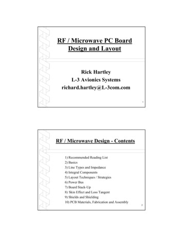
RF / Microwave Design Integral Components)Interdigital Capacitor-51RF / Microwave Design Integral Components)Interdigital CapacitorC2 ε r 1. 0wL[( N 3.0 )A1 A2] (pF / in) tA1 0.3349057 0.15287116 X 2 t A2 0.50133101 0.22820444 X (Equation valid for h w/N)252
RF / Microwave Design Integral Components)Multilayer Capacitor -C 0.229ε r A(n 1.0) (pF)dwhere:A area of planes in square inchesn number of conductor layersd plate spacing53RF / Microwave Design Integral Components)Inductor- Inline Inductor is formed by aVery Thin, High Impedance Trace.*Length Must be Shorter than Critical Lengthto Prevent Re
Trace Width & Trace-to-Ground Separation. *As Trace Width Increases, Trace Impedance Decreases (Thickness has Min Effect). *As Trace Spacing from Ground Increases, Impedance Increases. 24 RF / Microwave Design - Line Types and Impedance (Zo) Transmission Line History -)Two Coplanar Strips in 1936. Later Rolled Up to create Sealed Line.)Coax Lines during WWII.)Flat Stripline Using PCB .