Transcription
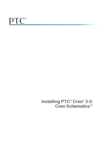
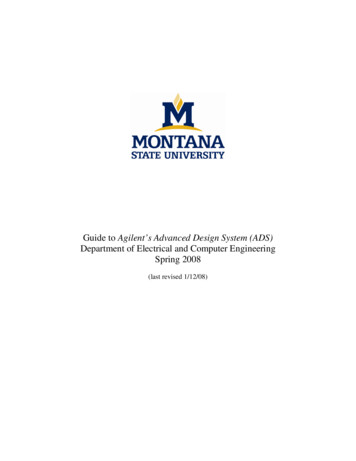
Refrigeration ServiceEngineers Society1666 Rand RoadDes Plaines, Illinois 60016UNDERSTANDING ELECTRICAL SCHEMATICSPart 2by Howard L. Pemper, CMSINTRODUCTIONfor example, shows both a normally open and a normally closed single-pole, single-throw (SPST) switch.This type of switch either opens or closes one circuit.Figure 1B shows a single-pole, double-throw (SPDT)switch. Again, only one circuit can be controlled atany given time, but in this case the switch has two different “connected” positions, which means that it candirect current to either of two paths.In this section, you will take a look at a packagedgas/electric system, which is a relatively complexheating and cooling unit. The wiring diagram for thisequipment is more difficult than those you studied inPart 1—but again, the schematic as a whole can besimplified by breaking it down into its basic circuits.As you examine individual control circuits and theassociated components that they operate, the overalldiagram becomes easier to understand, as do thevarious machine functions. The schematics in thissection may include some symbols with which youare not familiar. For your convenience, many of theschematic symbols currently used and recognized bythe HVAC/R industry are collected in Figure 16 at theend of this chapter.A. Single-pole, single-throw (SPST)Normally closed (N/C)Normally open (N/O)SWITCH SYMBOLSB. Single-pole, double-throw (SPDT)Generally speaking, a wiring schematic shows thecondition of a piece of equipment when there is nopower being applied to the unit. Therefore, if a switchis depicted as being normally open (N/O) or normallyclosed (N/C), remember that the position of theswitch is shown as it appears when there is no powerapplied to that circuit. If there is any deviation fromthis practice, there will be an explanatory note on theschematic.C. Double-pole, double-throw (DPDT)As you may know, a switch is characterized by thenumber of contacts (or poles) and the number ofpositions (or throws) it has. Think of the number ofpoles as the number of circuits that the switch cancontrol at one time, and the number of throws as thenumber of paths a single circuit can take. Figure 1A, 2003 by the Refrigeration Service Engineers Society, Des Plaines, ILSupplement to the Refrigeration Service Engineers Society.Figure 1. Switch symbols1630-141Section 4A n
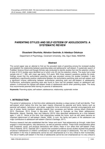
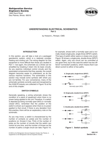
Double-pole, single-throw (DPST)operation of the control. In Figure 3, for example, thetemperature switch (RS-2) is shown with the armabove the contacts. This signifies that the switchopens on a rise in temperature and closes on a dropin temperature. The pressure switch (AFS-2) isshown with the arm below the contacts. This signifiesthat the switch opens on a drop in pressure andcloses on a rise in pressure.Double-pole, double-throw (DPDT)An example of an SPDT limit switch (LS) is shown inFigure 4. When there is an increase in temperature,the contacts “C” to “N/C” move to the “N/O” position.When the temperature decreases, the contacts “C” to“N/O” move back to the “N/C” position.RelaysRelays are electrically operated control switches. Theschematic symbols used to represent relays are thesame as those for manually operated switches,except that relay symbols often include a solenoidcoil. There are several possible ways of depicting thesolenoid coil. Figure 5 shows two different schematicrepresentations of a DPDT relay. Note that multiplepole relays, like multiple-pole switches, are connectedmechanically but not electrically.Three-pole, single-throw (3PST)ContactorsFigure 2. Multiple-pole switchesA contactor is a type of heavy-duty relay that handleshigher voltages and higher currents than a controlA switch that can control more than one circuit at atime is shown schematically as having more than oneset of contacts. Look back at Figure 1C on the previous page. It shows an example of a double-pole, double-throw (DPDT) switch, which can control twocircuits at the same time. The dashed line representsthe mechanical connection, and tells you that thecontacts move together, but are not connected electrically. Figure 2 above shows a few of the many othervariations that are possible in depicting multiple-poleswitches.RS-21AFS-2312Figure 3. Temperature and pressure controlsN/OControlsLSCPressure and temperature controls are switches, too,and they also may be configured with various combinations of poles and throws. The position of theswitch “arm” in the schematic symbol indicates theN/CFigure 4. SPDT limit switch2
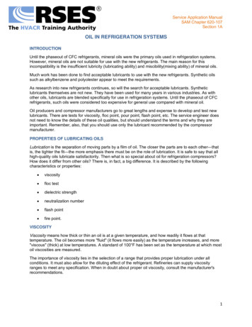
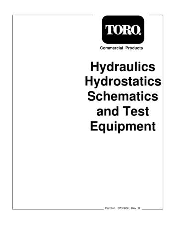
CoilCoilFigure 5. DPDT relaysrelay. Contactors appear nearly identical to relays onschematic diagrams. Some manufacturers employcontactors that use a single set of contacts. A “busbar” is placed over the connection where the otherset would be, as shown in Figure 6. Figure 16 at theend of this chapter includes many other symbols forswitches and relays.L1L2T1T2CoilFigure 6. Two-pole contactor with bus barTHE BASIC DIAGRAMproblems that you may encounter with a particulartype of equipment.Let’s take a look at a “generic” schematic of a packaged heating/cooling unit. In order to illustrate thevarious options that may be possible with a unit of thiskind, the schematic has been put together by takingparts from several different manufacturers. Becauseof its complexity, the schematic is broken into threeparts. Figure 7 (spread across pages 4 and 5) showsthe high-voltage components, and Figure 8 (pages 6and 7) shows the low-voltage or control circuits. Therenormally is no “point-to-point” or line diagram with thistype of schematic, but a component layout is oftenprovided. This is shown in Figure 9 (pages 8 and 9).RELAYSAs you saw earlier, relays can and do have manycontacts. A single relay may have a function in two,three, or sometimes four different circuits. Its contactsmay be located in various parts of the schematic, andyou must know how to find them if you are to knowhow the unit works. In our generic diagram, severalrelays provide lockouts for the cooling and heatingsections, which means that the two sections cannotcome on at the same time.EQUIPMENTLocate control relay CR-1 at the bottom of Figure 8(line 183). Now look at the detail shown in Figure 10A(found on page 10). As you can see, control relayCR-1 has five sets of contacts that are operated byone coil. The first two sets of contacts, CR-1a andCR-1b, are found on lines 42 and 48, respectively(see Figure 10B). The third set, CR-1c, is found online 77 (see Figure 10C). The fourth set, CR-1d, isfound on line 149 in the low-voltage section of theschematic (see Figure 10E). The last set, CR-1e, isfound on line 90 (see Figure 10D). Remember thatwhen a number in the right-hand margin of Figure 10Ais underlined, it designates a set of normally closed(N/C) contacts.In order to service any piece of equipment, you firstmust know what you are working with. Even beforeyou begin a visual inspection of the equipment itself,a quick look at the schematic will give you a generalidea of the type of equipment and its components. InFigure 7, for example, it’s easy to spot the two compressors—therefore, you can assume that this is atwo-stage cooling system. Likewise, in Figure 8 youcan see two ignition systems—again, you can conclude that this is a two-stage heating system. Withjust a quick glance at the schematic, you have determined what the unit is. As you become more experienced, you also may have a good idea of the kinds of3
Figure 7. High-voltage 625242322212019181716151413121110987654321YEL115 V208 VCB-1110 ABLUTRSF-1230 BLKBLUYELBLKRCSRCSC1 OFMC-2 C2C1 OFMC-1 C2CAPCAPIFMBLUYELBLKBRNBRNCOMP-1BRNC2 OFMC-2C2 OFMC-1TRSF-1OFM-2OFM-129, 3122, 24COMP-2
Figure 7. High-voltage circuits -1b4CCPSL2GRYGRYMOFC-2MOFC-1LHPS-12HPS-22120 V220 V120 V2 ASR-2 31220 V2 ASR-1 31C3C2C1 IDFM C2C1USLVC1 IFMC C2CC HTR-2OFC-2C1 TDR-2 C2C1 CC-2 C2OFC-14 TDR-1 6C1 CC-1 C2CC NBRNBRNBRNBRNBRNBRNBRNOFC-2TDR-1C2 IDFMC2 USLV-1C2 IFMC2 IFMC-2CC HTR-2CC HTR-1OFC-2C2 TDR-2C2 CC-2C2 CC-2BRN6C2 CC-1C2 CC-115, 17, 186363, 689, 10, 124848, 531, 3, 4
Figure 8. Low-voltage 5IGN-2IGN-1CCB-23ALS24 V115 V11GVR-2IGN -1IGNGV-2IGNGV-1T2T2C1 CR-7 C2VIOVIOVIOVIOVIOVIOT2IGN PCBIGN-2IGN-1C2 TRSF-2T2 GV-1T2 CR-7TRSF-2
Figure 8. Low-voltage circuits OGICTDR-313RGW2 W1 Y2 Y1CC1 CR-1 C2C1 CR-2 C2C1 HR-1 C2C1 HR-2 C2C1 IFRC C2C1 IFRH C2C1 IDFMR C2VIOVIOVIOVIOVIOVIOVIOVIOLOGICC2 USLV-1C2 CR-1C2 CR-2C2 CR-2C2 CR-2C2 HR-2C2 HR-1C2 IFRC3IDFMRC2 IFRHC2 IDFMR42, 48, 77, 149, 9063, 80, 146161, 152, 149158, 146858292
879635463C2C2Figure 9. Component 3IDFMR1 CCPS 2C2C241HR-1C2C2114152CR-752AFS-2 2AFS-1 GN-2GV-1T1GV-2W2 W1 Y2 Y1GVR-2IGN PCB21IFRC13 14 1541CR-2GGVR-1C1C15410 11 1221CR-1RCT2
Figure 9. Component layout 2TDR-1220 V 120 VOFC-2220 V 120 C2T3L3T2L2IFMCT2L2CC-2C2T3L3C1T1L1C2T3L3
Detail A178179180C2 CR-1181182C1 CR-1 C2183C2 USLV-1VIO42, 48, 77, 90, 149184185186187Detail B37383940FU-18ACR-1a134142BRNC2 OFMC-1C1 OFMC-2 C2BRNC2 OFMC-2ATS14344C1 OFMC-1 C23GRYBRN45464748CR-1b4ASR-161OFC-13LM1213C1 CC-1 C2BRNC2 CC-14950HPS-1LPS-151Detail C757677CR-1c12CC HTR-1GRYBRNCC HTR-17879878889Detail DCR-1e1315USLVCCPS12C19091Detail E14714814915079HR-1c1012CR-1d151152Figure 10. Locating control relay contacts10C2C2 USLV-1
CC-1CR-1bASR-1OFC-1HPS-1LPS-1Figure 11. Series circuitCIRCUITSflow is indicated by the arrows. Notice that the currentmust pass through all of the switches before it canenergize the coil. If any of the switches is open, thecoil cannot be energized.A schematic diagram can look complicated whenviewed as a whole. However, as stated previously, itbecomes much easier to analyze a problem if youbreak down the large diagram into smaller individualcircuits. All electric circuits conform to one of threebasic arrangements.Parallel circuitsIn a parallel circuit, there are two or more separatepaths or branches for current flow. A parallel circuitarrangement allows any one of a number of controlsor switches to energize a load. Look at Figure 12A,for example. When either of relay contacts IFRH orIFRC is closed, current will pass through the circuitand energize coil IFMC. However, note that bothIFRH or IFRC must be open in order for the coil to bede-energized.Series circuitsIn a series circuit, components are arranged one afteranother, so that the same current flows through all ofthe components in one continuous path. Figure 11shows an example of a number of switches and arelay coil connected in series. The direction of currentA. Multiple switches, single loadIFMCIFRHIFRCB. Single switch, multiple loadsOFMC-1CR-1aATSOFMC-2Figure 12. Parallel circuits11
CC-1CR-1bASR-1OFC-1HPS-1LPS-1TDR-1ASR-1220 VTDR-1120 VHeaterOFC-1Figure 13. Series-parallel circuitA single switch can energize several loads at thesame time in a parallel circuit. All of the loads will getthe same amount of current when the switch closes.In Figure 12B, for example, when switch CR-1a isclosed, current will pass through the circuit and energize coil OFMC-1. And as long as thermostat ATS isclosed, coil OFMC-2 also will be energized.multiple-path) circuits. Such a circuit allows someoperations to proceed while stopping others. Seriesparallel circuits are primarily used in control andsafety applications. The detail shown in Figure 13above illustrates a series-parallel circuit. When switchCR-1b closes, current flows through both branches ofthe circuit. As long as all of the switches ASR-1,OFC-1, HPS-1, and LPS-1 are closed, currentpasses through the upper branch and energizes coilCC-1. If any of the switches is open, however, thecurrent will be allowed to pass only through the lowerbranch to coil ASR-1.Series-parallel circuitsAs the name implies, a series-parallel circuit is acombination of series (or single-path) and parallel (orC1 IDFMR C2IFRHC2 IDFMRIDFMR123123456456C2 IFRHC1 IFRH C2C1IDFMRA. Schematic diagramC2C1B. Component diagramFigure 14. Terminal connections12C2
With all of the switches in the upper branchclosed and coil CC-1 energized, currentsimultaneously passes through the TDR-1contacts to the TDR-1 relay. This is a“delay-on-make” time-delay relay, whichmeans that after a specified period of time,the TDR-1 contacts will open. This type ofcontrol is commonly used for low-pressurebypass during low ambient conditions.When coil CC-1 is energized, note that current also passes through the 120-V resistor, through the resistor marked “Heater,”and through differential pressure controlOFC-1. This is an oil failure control. Whenoil pressure is sufficient, differential pressure control OFC-1 will open, thus takingthe heater out of the circuit and preventingthe OFC-1 contacts from opening.IGN-1GVR-2IGN-1IGN PCBIGN-2CONNECTIONS AND WIRINGGVR-1GVR-2Figure 15. Relay connections on igniter printedcircuit boardIn order to conserve wire and space, somemanufacturers terminate more than onecoil connection at the same point. This practice isdepicted schematically as shown in Figure 14A,where the terminals from the IDFMR and the IFRHare taken off the same terminal connection. Note thatthe schematic shows two connections or wires at thatpoint (the arrows point to the connection points).Because line diagrams are not used in complexschematics, the component diagram will show theterminal connections on the relays and other devices(see Figure 14B).contacts for the igniters are on the printed circuitboard, but they cannot be physically replaced. Thecontacts themselves are usually shown enclosed in a“box” drawn with dashed or dotted lines. This sameapproach is used for the gas valve relay shown inFigure 15, and in some instances for fan relays aswell.LEGENDSThere normally isn’t enough space on a schematic toaccommodate the full spelling of each component. Alegend listing many of the abbreviations used in theschematic that you have been studying is shown onthe next page.In some cases, a control or relay may not be shownas a replaceable item, or even as a component thatcan be tested. In Figure 15, for example, the timing13
LEGENDAFS . . . . . Air flow switchIDFM . . . . . Inducer fan motorASR . . . . . Anti short-cycle relayIDFMR . . . . . Inducer fan motor relayATS . . . . . Air temperature switchIFM . . . . . Indoor fan motorCAP . . . . . CapacitorIFMC . . . . . Indoor fan motor contactorCB . . . . . Circuit breakerIFRC . . . . . Indoor fan relay (cooling)CC . . . . . Compressor contactorIFRH . . . . . Indoor fan relay (heating)CC HTR . . . . . Crankcase heaterIGN PCB . . . . . Igniter printed circuit boardCCPS . . . . . Capacity control pressureIGN . . . . . IgniterswitchLPS . . . . . Low-pressure switchCOMP . . . . . CompressorLS . . . . . Limit switchCR . . . . . Cooling relayOFC . . . . . Oil failure controlCS . . . . . Centrifugal switchOFM . . . . . Outdoor fan motorFS . . . . . Flame sensorOFMC . . . . . Outdoor fan motor contactorFU . . . . . FuseRS . . . . . Rollout switchGND . . . . . GroundTB . . . . . Terminal boardGV . . . . . Gas valveTDR . . . . . Time-delay relayGVR . . . . . Gas valve relayTRSF . . . . . TransformerHPS . . . . . High-pressure switchULSV . . . . . Unloader solenoid valveHR . . . . . Heating relayNote: Figure 16 on the following three pages showsmany of the schematic symbols used in the HVAC/Rindustry today.14
SWITCHESN/OorN/CorCloseson fallCloseson risePushbutton -O-A switchHANDSPDTOFFLiquid levelAUTOFoot switchesFlowDPSTN/ON/CLimitTime-activated zedRELAYSCoilSPST(N/O)CoilDPSTCoilCoilCoilSPST (N/O)SPST DPDTL1L1L2CoilT12-pole contactorT2L1L2CoilL2L3CoilT1T2T12-pole contactorwith bus barT23-pole contactorFigure 16. Schematic symbols15L1L2L3T1T2T3CoilT33-pole contactorwith bus bar
TRANSFORMERSPrimary115 VCurrent transformerBoost-and-buck transformerSecondary24 V“Boosting”24 V460 V230 V208 V120 V“Bucking”2.5 VCommonMultivoltage control transformersCommonTapped460-V primary460-V -V secondary120-Vsecondary230-VprimaryAir core115 V10 V secondaryAlways consult the manufacturer’snameplate for proper connections.High-voltage transformerCircuit breakersFusesCartridge orplug fuse120-VsecondaryThermal overloadswitchFusible linkSinglepoleDoublepoleOverload safetyswitchTriplepoleMechanicalinterlockThermal overloadFigure 16. Schematic symbols (continued)16Magnetic overloadswitch
Ground res crossingbut not connectedThermocoupleEarthgroundLampCapacitor (fixed)BatteryTerminalnearest groundShielded cableELECTRONIC AND gateNumber of conductorsin conduit or cableBSCRConnectorsENPNNAND gateMaleCBFemaleLEDOR gateEPNPEngaged(plug and receptacle)DiacNOR gateDGResistorsSN-channel JFETFixedTriacNOT gateDGPotentiometerZener diodeVariableSBuffer ampP-channel JFETRheostatTunnel diodeOp ampTappedUJTPhotodiodeResistance heaterSolenoidThermistorMOVTCad cellFigure 16. Schematic symbols (continued)17IGT
Refrigeration Service Engineers Society1666 Rand RoadDes Plaines, IL 60016847-297-6464
5 brn 3 1 brn gry gry cc-1 cc-1 c1 c2 c2 cc-1 c2 brn tdr-1 tdr-1 4 6 asr-1 2 3 6 brn ofc-2 lps-1 c c tdr-1 2 1 4 6 1 3 l m hps-1 cr-1b asr-1 ofc-1 blu red ofc-1 brn cc-2 cc-2 c1 c2 c2 cc-2 c2 brn