Transcription
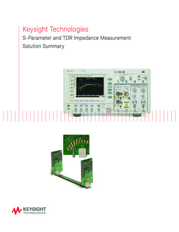
Keysight TechnologiesS-Parameter and TDR Impedance MeasurementSolution Summary
02 Keysight S-Parameter and TDR Impedance Measurement Solution SummaryTDR measurements are keystep toward signal integrity– Built-in S-parameter testing– Easy and accurate transmissionchannel/media characterizationTransmission lines for high speed digital communications, such as connectors and printedcircuit boards, are required to carefully control theimpedance, which may affect the signal integrityof today's fast signals. New standards such asPCI-Express and Keysight Technologies, Inc.Serial ATA need accurate characterization of theS-parameters and impedance. With enhancedTDR measurements capabilities, Keysight responds to these test requirements.The simplest coniguration for TDR (Time DomainRelectometry) measurements is a step generatorwithin a wide bandwidth oscilloscope. The relected signal from the step generator is relectedand represented as voltage or impedance as afunction of time. TDT (Time Domain Transmission)typically shows transmission delay. Impedancediscontinuities with a device or channel causedistortion of the transmitted signal and TDR/TDTis an important tool to improve signal integrity.The powerful combination of the Keysight 86100series Ininiium DCA mainframe and the 54754ADifferential TDR module provides a superb solution for TDR/TDT measurements for many years.While responding to a signiicant demand in recent high speed digital serial interfaces, TDR/TDTmeasurement features are signiicantly enhancedfor easy and accurate results.*New setup menu iseasy-to-understandand easy-to-useThe new set-up menu, with a graphical user interface, provides an intuitive operation, even forusers unfamiliar with TDR. Connections betweenthe device-under-test (DUT) and the test portsare graphically displayed, once the stimulus modeand type of device ports are selected. With the86100C option 202 installed, not only the timedomain results of TDR/TDT are shown, but thefrequency results of S-parameters are also displayed (refer to page 4 for detail).*Note: This document will discuss features available in the 86100C as amainframe with firmware revision 6.0 and above installed. Some of thefeatures are available in the 86100B mainframe with revision 5.0 installed.These features are not available in the 86100A mainframe.
03 Keysight S-Parameter and TDR Impedance Measurement Solution SummaryTDR Calibration is thequickest way tocorrect resultsTo obtain accurate test results, systematicerrors introduced from test ixture or cablesmust be correctly removed. Keysight TDRCalibration establishes a calibration planewith digital ilter technologies using Shortand Load reference devices, then removessystematic errors to provide accurate results.This can be easily demonstrated by connecting two identical TDR demo boards in series.The irst board emulates a test ixture, whichdegrades the test results of second boardin left. After applying the TDR Calibrationbetween the connector of two boards, theeffect of irst board (ixture) is calibrated-outto show a 50 ohm trace, and the result ofthe second board is shown as expected onthe right side of the trace. The new revision5.0/6.0 and above adds a feature called timeinvariant TDR calibration, that maintains thecalibrated trace results even after changingtime-span (sec/div) or delay position.Complete single-endedand differential testing relies on the electromagnetictheoryThe Keysight Differential TDR solution usessuperposition to obtain all of the requiredS-parameters including return loss, attenuation and crosstalk and report the results insingle-ended, differential or common mode.Full differential capability is enabled with theuse of a second module with dual electricalchannels such as the 54754A or 86112A.Kit for Complete TDRCalibrationN1024B TDR Calibration kit enablesyou to perform accurate differentialTDR/TDT and S-parameter measurements. Based on extensive SOLT(Short-open-load-thru) calibrationtechnology in VNA (Vector NetworkAnalyzer), the measured results usingthe 86100 Ininiium scope and TDRmodule favorably compare to VNAmeasurements to greater than 15 GHz.N102ACalibration Kit (3.5 mm)DeviceQtyPart #Male Load200902-60003Male Short20960-0055Female Load200902-60004Female Short21250-1834Cables48120-4948BNC-M to SMA-F11250-17003.5mm F-F25061-5311Torque Wrench18710-1765
04 Keysight S-Parameter and TDR Impedance Measurement Solution Summary86100C Option 202 extendsthe TDR capabilityThe 86100C option 202 EnhancedImpedance and S-parameterSoftware extends the capability ofTDR/TDT measurements.One touch display forS-parametersThe 86100C Option 202 software offersfrequency domain results of S-parameters(S11 return loss or S21 insertion loss) from timedomain TDR/TDT results quickly in a singletouch . Up to 6 parameters can be displayedsimultaneously and a marker readout quicklypinpoints the values at the desired frequencyand allows comparison between traces. Timedomain gating function is available, since thefrequency data is calculated for the area between the reference plane (at t 0, or markerof triangle) and right most edge.Impedance correction dueto multiple relectionsMultiple and subsequent impedance-discontinuities often diminish the reported size, orimpedance value, at the position of discontinuities. The 86100C Option202 software addsthe TDR Peeling function to calculate thecorrect impedance value, therefore compensating for these multiple relection effects.Extract results toTouchstone ilesWith the 86100C Option 202 software,S-parameter results can be exported to otherapplications through the use of a Touchstoneile for use in circuit simulation with both .s1pand .s2p formats. The .s2p format providesfour S-parameters, two in each direction. Ifone TDR module and one dual receiver isused, the device is turned around to obtainthe reverse parameters. If two TDR modulesare used, the measurements can be quicklyreconigured to obtain the reverse parameterswithout turning the device around.*Note: 86100C users can obtain the license for the 86100C Option 202 by ordering the86100CU Option 202 upgrade kit. 86100C Option 202 and 86100CU Option 202 are notavailable in the 86100A/B.
05 Keysight S-Parameter and TDR Impedance Measurement Solution SummaryQuality of TDR steppulse is a key ofimpedance testingThe quality of the TDR step pulselaunched into the DUT inluences theTDR measurements. The 54754A isdesigned carefully to minimize the aberration providing a clean pulse withsmall overshoot and ringing; this virtually eliminates any confusion amongsmall actual relections. Digital iltering derived from the TDR Calibrationallows the user to simulate differentstep pulse speeds to verify how theimpedance is seen under actual signalpulse speeds. Also a simulation withsteps as fast as 10 ps can be displayedwith TDR Calibration, resulting in accurate impedance measurements ofsmall and high speed devices.Improve resolution bymaking actual steppulse fasterPicosecond Pulse Lab's source enhancement module provides a quickand accurate view of closely spaceddiscontinuities, by applying a 9 ps steppulse instead of standard approximate 35 ps step pulse. Please notethat appropriate receiver bandwidthis needed to be used with the PSPLmodule (4020 or 4022). The 86118A isthe best receiver with 70 GHz bandwidth and contains remote heads toeliminate degradation from cables tothe DUT. TDR calibration with recommended 2.4mm calibration devicesestablishes a clean pulse by removingany aberration effects.Refer to PSPL information athttp:/www.picosecond.com/.Step pulse 18 ps 25 ps 30 ps uncalibrated.Image ile : 13Gbps board, S-E TDR, showing raw, 30ps, 25ps and 18pstraces, white.jpg54754A TDR step typical speciication:Step rise time : 35 psStep latness : 5/-3% up to 1 ns 1 % beyond 1 ns
06 Keysight S-Parameter and TDR Impedance Measurement Solution SummaryComplete differentialcharacterization via PLTSS-parameter testing with the 86100COption 202 provides easy viewing of up tosix simultaneous S-parameters. The N1930APhysical Layer Test Solution, based on eitherTDR or VNA, offers a complete solution fora differential line characterization. PLTSis designed to provide 16 simultaneousS-parameters and extensive calibration, as wellas an eye diagram simulation.For more accurate results, use the VNA.N5230A option 220 PNA series is a 4 port20 GHz Network Analyzer as a best companion for the PLTS solution with widerdynamic range and advanced calibrationsuch as TRL (Thru-the-line).Comparison betweenanalyzersVNA is recognized as the most accurateand widest dynamic range solution in theworld to characterize transmission lines.The right graph shows a comparisonof differential return loss test (SDD11)between the VNA and the TDR with an actual device under test. Blue is a TDR withTDR Calibration, which shows very goodmatching with VNA (red) up to about 10GHz. This results show that S-parametersusing TDR Calibration are comparable toVNA results.N5230A-220DCA-Jwith 202PLTSwith TDRS-parametercoverage3232Simultaneousdisplay ofS-parameters616# of CalibrationsMoreFewerCapabilityVery goodBetterDynamic range 45 dB 45 dBMainframesupported86100C86100A/B/C
07 Keysight S-Parameter and TDR Impedance Measurement Solution SummaryVersatile TDR accessoriesN1020A TDRprobe kitN1020A-K05Calibration SubstrateN1020A-K09,10,11 TDRCablesN1020A TDR probe kit is a generalpurpose single-ended TDR probe witha test armature to locate the probe byX-Y-Z positioning. The N1020A-K05Calibration Substrate is included.Using the precision, thick ilm resistorsthat are laser trimmed, this substrateyields the utmost in accuracy to allowTDR Calibration at the end of probetip.SMA connecters are directly connected to three type of high speed digitalinterface connectors. Short and Loadconnectors for TDR Calibration areincluded.– FireWire (IEEE 1394)– Gigabit Ethernet (IEEE 802.3Standard) High Speed Serial Data Connector (HSSDC)– Fibre Channel (ANSI x3.297-1997)DB-9Bandwidth : 6 GHzProbe pitch : 1.5 to 5.0 mmDifferential TDRprobe kitCare for preventing ESD troubleGeneral purpose single-ended anddifferential probe kits with virtualgrounds are designed to completeTDR Calibration with probes using thecalibration substrate.Bandwidth : 15 GHz TypicalProbe pitch : 0.5 to 3.0 mmInput of the 54754A TDR module consists of aprecision microwave sampler with maximum input voltage of /- 2 V DC. Any cable or PC boardto be measured is subject to charge the electrostatic voltage beyond 1000V. This ESD causesdamage to the TDR module input circuitry. Theuser is strongly advised to discharge the printedcircuit boards, ixtures and cables prior to connection to the TDR input, by shorting the innerand outer conductors on the tab or edge ofconnector on the front of the TDRmodule, or bytouching a grounded-probe onto the trace of PCboard. Plugging in anti-static wrist strap to themainframe and attaching the strap to your wristis also highly recommended. Picosecond ATEoffers a static protection unit for use in sensitiveenvironments.
08 Keysight S-Parameter and TDR Impedance Measurement Solution Summary86100C DCA-J has a powerfulsolution - Jitter AnalysisThe 86100C is a powerful wide bandwidth oscilloscope which enables accurate RJ/DJ separation, TJ (Total Jitter) analysis, and detailed jitter decomposition. The 86100C Option 200 software allows simple operation through aone-key solution, then displays the jitter test results in histogram charts andtabular format. Frequency extraction of periodic jitter (PJ) further enhancestroubleshooting. The core technology is in the option 001 Extended Trigger,which uses PatternLock to display a single value waveform allowing preciseanalysis of each edge.Equalizer SimulationHigh speed digital signals are often affected by intersymbol interference (ISI)which is due to bandwidth limitations of transmission line such as PC boards.One very effective solution is to equalize the receiver circuit. The 86100COption 201 provides a Linear Feedforward Equalizer simulation to estimate theeye shape after your equalizer circuit. This is facilitated by quickly choosingthe tap spacing and values, either automatically or manually.Recommendedconiguration forsystem on front page– 86100C Ininiium DCA-J mainframe– 86100C option 202 EnhancedImpedance and S-parameterSoftware– 54754A Differential TDR module– 86112A Dual 20GHz Electrical Module (for differential TDT measurement)– N1024B TDR Calibration kit.
09 Keysight S-Parameter and TDR Impedance Measurement Solution SummarymyKeysightwww.keysight.com/find/mykeysightA personalized view into the information most relevant to you.www.axiestandard.orgAdvancedTCA Extensions for Instrumentation and Test (AXIe) is anopen standard that extends the AdvancedTCA for general purpose andsemiconductor test. Keysight is a founding member of the AXIe consortium.ATCA , AdvancedTCA , and the ATCA logo are registered US trademarks ofthe PCI Industrial Computer Manufacturers Group.For more information on KeysightTechnologies’ products, applications orservices, please contact your local Keysightoffice. The complete list is available azilMexicoUnited States(877) 894 441455 11 3351 7010001 800 254 2440(800) 829 4444Asia PaciicAustraliaChinaHong KongIndiaJapanKoreaMalaysiaSingaporeTaiwanOther AP Countries1 800 629 485800 810 0189800 938 6931 800 112 9290120 (421) 345080 769 08001 800 888 8481 800 375 81000800 047 866(65) 6375 8100www.lxistandard.orgLAN eXtensions for Instruments puts the power of Ethernet and theWeb inside your test systems. Keysight is a founding member of the LXIconsortium.www.pxisa.orgPCI eXtensions for Instrumentation (PXI) modular instrumentation delivers arugged, PC-based high-performance measurement and automation system.Three-Year sight’s commitment to superior product quality and lower total costof ownership. The only test and measurement company with three-yearwarranty standard on all instruments, worldwide.Keysight Assurance Planswww.keysight.com/find/AssurancePlansUp to five years of protection and no budgetary surprises to ensure yourinstruments are operating to specification so you can rely on ght Technologies, Inc.DEKRA Certified ISO 9001:2008Quality Management SystemKeysight Channel Partnerswww.keysight.com/find/channelpartnersGet the best of both worlds: Keysight’s measurement expertise and productbreadth, combined with channel partner convenience.Europe & Middle rlandUnited Kingdom0800 0011220800 585800800 5232520805 9803330800 62709991800 8327001 809 343051800 599100 32 800 585800800 02332008800 50092860800 0001540200 8822550800 805353Opt. 1 (DE)Opt. 2 (FR)Opt. 3 (IT)0800 0260637ATCA , AdvancedTCA , and the ATCA logo are registered US trademarks of the PCIIndustrial Computer Manufacturers Group.For other unlisted countries:www.keysight.com/find/contactusPCI-SIG , PCIe and the PCI Express are US registered trademarks and/or servicemarks of PCI-SIG.(BP-07-01-14)This information is subject to change without notice. Keysight Technologies, 2011 - 2014Published in USA, August 1, 20145989-4149ENwww.keysight.com
Analyzer), the measured results using the 86100 Ininiium scope and TDR module favorably compare to VNA measurements to greater than 15 GHz. N102ACalibration Kit (3.5 mm) Device Qty Part # Male Load 2 00902-60003 Male Short 2 0960-0055 Female Load 2 00902-60004 Female Short 2 1250-1834 Cables 4 8120-4948 BNC-M to SMA-F 1 1250-1700 3.5mm F-F 2 .
