Transcription
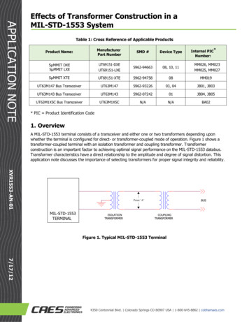
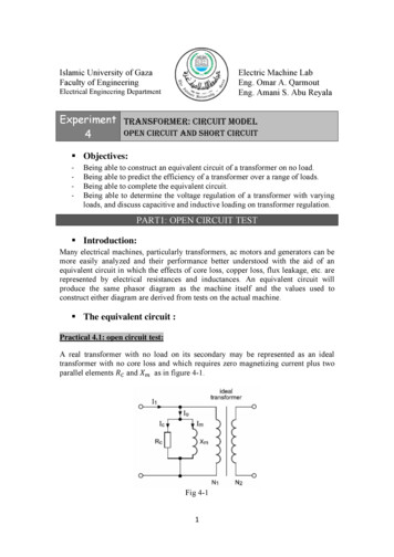
Islamic University of GazaFaculty of EngineeringElectric Machine LabEng. Omar A. QarmoutEng. Amani S. Abu ReyalaElectrical Engineering DepartmentExperiment TRANSFORMER: CIRCUIT MODELOPEN CIRCUIT AND SHORT CIRCUIT4 Objectives:‐‐‐‐Being able to construct an equivalent circuit of a transformer on no load.Being able to predict the efficiency of a transformer over a range of loads.Being able to complete the equivalent circuit.Being able to determine the voltage regulation of a transformer with varyingloads, and discuss capacitive and inductive loading on transformer regulation.PART1: OPEN CIRCUIT TEST Introduction:Many electrical machines, particularly transformers, ac motors and generators can bemore easily analyzed and their performance better understood with the aid of anequivalent circuit in which the effects of core loss, copper loss, flux leakage, etc. arerepresented by electrical resistances and inductances. An equivalent circuit willproduce the same phasor diagram as the machine itself and the values used toconstruct either diagram are derived from tests on the actual machine. The equivalent circuit :Practical 4.1: open circuit test:A real transformer with no load on its secondary may be represented as an idealtransformer with no core loss and which requires zero magnetizing current plus twoparallel elementsandas in figure 4-1.Fig 4-11
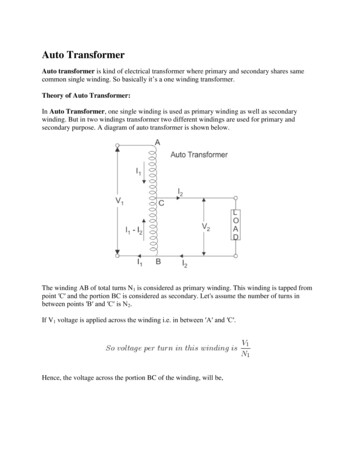
The resistanceis the core loss element. The current through this will be in phasewith the applied voltage and will dissipate power equivalent to that of the core at aspecified voltage and frequency. The reactanceis the magnetizing element. Itscurrent will lag the applied voltage by 90 ; i.e. it is in quadrature with the appliedvoltage, and no power is dissipated. The current taken byproduces the magnetomotive force which sets up the flux in the core.By measuring the current and power taken from the supply, as shown in figure 4-2,values for the elements of the equivalent circuit can be derived and the phasordiagram constructed.Fig 4-2Using the test results obtained in this assignment a phasor diagram similar to that infigure 4-3 can be constructed.Fig 4-3We will first calculate the phase angle between the current and the primary voltageV1, and then derive values for the core loss and magnetizing currents.Let primary power input (wattmeter ) Voltage applied to primary (voltmeter ) Voltage applied to secondary (voltmeter ) Total primary current on no load (ammeter ) In phase component of current I (core loss component) Quadrature component of current I (magnetizing component) phase angle betweenand .2
We can now calculate the currents through the core loss resistanceand themagnetizing reactancealso the phase relationships between these currents and theprimary voltage.A word of explanation is needed as to why we refer to the total primary current on noload asinstead of . represents the phasor sum of the core loss current andthe magnetizing currentas shown in figure 4-3. When the transformer is supplyingno external load, this is the total current taken by the primary, therefore for thiscondition . when the transformer is supplying a load, there is a large additionalcurrent flowing in the primary and in this case I1 is not equal to Io but to the phasorsum ofand primary load current component.The apparent power taken by the primary on no load is:And the power input is:cos Hence: cosAnd;cos (Core loss component in phase with the applied voltage)sin (Magnetizing component in quadrature with applied voltage) Procedure:1. Ensure that the power supply (unit 8821-25) is switched off.2. Make the appropriate connections either for virtual or conventionalinstrumentation shown in figure 4.2 using unit 8341-05.3. In the virtual instrumentation set the range of ammeters in low mode.4. Ensure the dial on the power supply is set to zero position.5. Switch on the power supply unit and using the output voltage dial, set thephase voltage to 200 V as shown on the virtual or conventional voltmeter E1.6. Measure the primary current and the secondary voltage, and record the resultsin table 4-1.7. On virtual or instrumentation, record the primary input power to thetransformer in table 4-1.Primary voltsPrimary currentInput powerSecondary voltsTable (4-1) Exercise 4.1:Calculate cos , the angle , andThen construct the phasor diagram.from the test results recorded in table 4-1. Exercise 4.2:Now that the currents andhave been evaluated, we can find the values of theequivalent core loss resistanceand magnetizing reactance. Draw the equivalentcircuit for the transformer on no load and insert these values into it. The methods ofcalculatingandis detailed in introduction section of this assignment.3
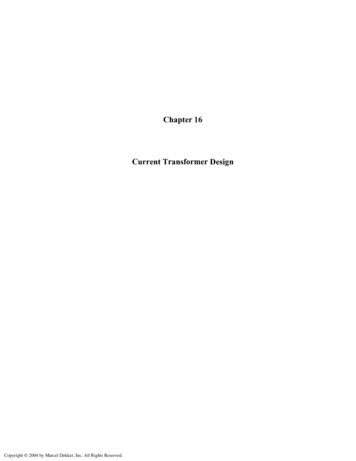
Exercise 4.3:Deduce the turns' ratio from your results in table 4-1. Exercise 4.4:A transformer has a turns' ratio of 0.5. An open circuit test is performed on theis found to be 600Ω andis found to be 160Ω. Calculate theprimary andvalues ofandwhich would have been found if you had performed the opencircuit test on the secondary winding instead of the primary. Practical Aspects:The equivalent circuit which you have constructed in this assignment provides amodel of the transformer on no load which is compatible with the phasor diagram. Atthis stage, it does not provide a complete model, since the effect of load current in thewinding impedance has not been considered. In the next assignment, we will add thecircuit elements necessary to complete the equivalent circuit of the transformer.PART2: SHORT CIRCUIT TESTPART1: THREE PHASE VOLTAGE AND CURRENT Winding resistance:Each winding of a transformer has resistance. When a current flows this gives rise to avoltage drop and to a power loss, usually referred to as the 'copper loss'Copper loss Leakage reactance:The flux produced by current flow in the primary turns does not all link with thesecondary turns. Similarly, the counter flux produced by load current in the secondaryturns does not all link with primary turns.The effect of leakage flux in a real transformer is similar to having an idealtransformer in which all the flux links both windings, plus separate inductorsconnected in series with the primary and secondary. In the equivalent circuit,reactanceandwill represent the leakage components in series with the primaryand secondary windings. Completing the equivalent circuit:By adding the winding resistances and leakage reactance to the equivalent circuit ofthe transformer on no load, we can extend it to form a complete model of thetransformer. The degree of complexity to which the equivalent circuit is taken willdepend on the particular application for which it is to be used. The completeequivalent circuit is shown in figure 4-4.The magnitude of the total effective winding resistance and leakage reactance can befound by placing a short circuit across the secondary, and finding out how muchvoltage at the primary terminals is needed to drive the rated current through thetransformer. This voltage will be quite small, so that the core losses (the effect ofand) will be negligible. The required circuit is shown in figure 4-5.4
Fig 4-4Fig 4-5There is, however, a preliminary test which we shall undertake in order to overcomesome limitations in our laboratory situation. In industry, the testing of a transformerwould be carried out with high accuracy instruments, regularly recalibrated. Also ithappens that in large transformers (for which open and short circuit tests are mostvaluable) the results are not usually nearly as dependent on measurement errors as inour small one. The reasons will become apparent later. But to ensure that you getgood results it will be advisable to check that the voltmeter, ammeter andelectrodynamic wattmeter are consistent with one another if conventionalinstrumentation is used. Calculation of winding resistance and leakage reactance:The input power which is measured in the short circuit test is unlikely to be the sameascalculated from measurements. Let us suppose for the moment that theimpedance at the primary terminals is a series combination of resistanceandreactance .Then since there is no power dissipated in the reactance:So that: Also the total impedance is:So that can be calculated asNote that only a single resistance and a single reactance value are obtained from thesecalculations. We must find out how they are related to the individual primary andsecondary resistances and reactance.5
Practical 4.2: short circuit test: Procedure:1. Ensure that the power supply (unit 8821-25) is switched off.2. Make the appropriate connections either for virtual or conventionalinstrumentation shown in figure 4.5 using unit 8341-05.3. In the virtual instrumentation set the range of ammeters in low mode.4. Ensure the dial on the power supply is set to zero position.5. Switch on the power supply unit and using the output voltage dial, set thephase voltage to 200 V as shown on the virtual or conventional voltmeter E1.6. Measure the primary current and the secondary voltage, and record the resultsin table 4-2.7. On virtual or instrumentation, record the secondary input power to thetransformer in table 4-2.Primary voltsPrimary currentInput powerSecondary current0.2Table (4-2) Exercise 4.5:Calculate the values ofand . Draw the equivalent circuit of the transformer inthe form having all impedances on the primary side of the ideal transformer. Mark inthe values calculated in this practical and include values forandfrom part 1.Practical 4.3:1. Ensuring that the power supply is switched off, remove the connections to thesecondary ammeter.2. Switch on the power supply and read the power indicated on the virtualwattmeter.3. The value of the core loss during the short circuit test would have been muchless than the quantity measured in this practical. This is because the core fluxwill have been roughly halved by the reduction in voltage due to the current inthe primary resistance and leakage inductance.4. Since eddy current loss is proportional to the square of the flux density andhysteresis loss, a fair estimate of the core loss in the short circuit test is aboutone quarter of the loss you measured with the short circuit removed. Practical aspects:1. It may seem that it would be far simpler to measure the winding resistancewith an ohm meter, and the leakage reactance may seem rather uncertain fromyour measurements. But consider the situation with a very large transformer.2. Large transformers have thick conductors in order to pass large currentswithout excessive heating. The resistance is often too low to measure with anordinary ohmmeter and in any case may differ between ac and dc values, sois better determined by the ammeter and electrodynamic wattmeter methodusing ac.6
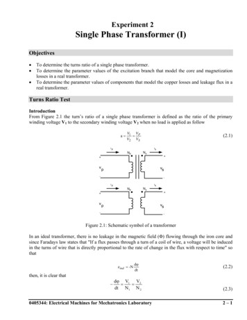
3. You may have found the reactance uncertain because its calculation involved asmall difference between two large quantities. But in a large transformer, thereactance is usually much larger than the resistance and, in this case, the errorsof the measurement matter far less.PART3: TRANSFORMER REGULATIONPART2: SHORT CIRCUIT TEST Introduction:The load on a large power transformer in a sub-station will vary from a very smallvalue in the early hours of the morning to a very high value during the heavy peaks ofmaximum industrial and commercial activity. The transformer secondary voltage willvary somewhat with the load, and because motors, incandescent lamps, and heatingdevices are all quite sensitive to voltage changes, transformer regulation is ofconsiderable importance. The secondary voltage also depends upon whether thepower factor of the load is leading, lagging, or unity. Therefore, it should be knownhow the transformer will behave (its voltage regulation) when connected to acapacitive, an inductive, or a resistive load. Transformer voltage regulation in percentis determined with the following formula:Where ENL: is the no-load secondary voltageEFL: is the full-load secondary voltageThe result (a percentage value) obtained gives an indication of transformer behaviorunder load. The smaller the voltage regulation percentage, the smaller the secondaryvoltage variation with load, and the better the voltage regulation. Note that ENL ismeasured with the secondary winding open while EFL is measured when nominalcurrent flows in the secondary winding.Several factors affect a transformer's operation. The resistance and inductivereactance of its windings cause internal voltage drops that vary with the amount ofcurrent flowing in the windings. If the secondary is lightly loaded, current through thewinding resistance and reactance is small and the internal voltage drops are notsignificant. As the load increases, current and internal voltage drops also increase. If atransformer was perfectly ideal, its windings would have neither resistance norinductive reactance to cause voltage drops. Such a transformer would have perfectregulation under all load conditions and the secondary voltage would remainabsolutely constant. But practical transformer's coils are made of real wire, andthereby, have resistance and inductive reactance. Therefore, the primary andsecondary windings have an overall resistance R, and an overall reactance X. Thesimplified equivalent circuit of a practical transformer with a 1:1 turns' ratio can beapproximated by the circuit shown in Figure 4.6. The actual transformer terminals areP1, P2 on the primary side, and S1, S2 on the secondary side.7
Figure 4.6: Simplified Equivalent Circuit of a Practical TransformerIn this equivalent circuit, the practical transformer is shown to be made up of an idealtransformer in series with an impedance consisting of R and X that represents theimperfections of the transformer. When a load (Z) is connected to the secondarywinding terminals (terminals S1 and S2), a series ac circuit consisting of the secondarywinding of the ideal transformer, R, X, and Z is obtained. Analysis of this series accircuit shows that when the load is either resistive or inductive, the load voltagedecreases continuously as the load increases (as the secondary current increases).Furthermore, when the load is capacitive, the load voltage increases to a maximum asthe load increases from zero (no load condition), and then, the load voltage decreasesas the load continues to increase. Procedure:1. Ensure that the power supply (unit 8821-25) is switched off.2. Set up the transformer loading circuit shown in Figure 4.7. Ensure that allswitches on the Resistive, Capacitive, and Inductive Load modules are open,and connect E1, E2, I1, I2 as shown in the figure. Different load values will beused to examine how the secondary (load) voltage changes as transformerloading changes.3. In the virtual instrumentation set the range of ammeters in low mode.Figure 4.7. Transformer With a Variable Load4. Turn on the main Power Supply and adjust the main voltage control to obtainthe value of ES given in Figure 4.7. With no load on the transformer (allswitches open on the load module), Measure EPRI, IPRI, ESEC, and ISEC andrecord them in table (4.3).5. Adjust the switches on the Resistive Load module to successively obtain theresistance values given in table (4-3). For each resistance value, record themeasurements as in step 4.8
VPRI(V) VSEC (V)R(Ω)4400 2200 1100 IPRI(I)R(Ω)4400 2200 1100 ISEC(I)R(Ω)4400 2200 1100120180200220Table (4-3)6. Display the Graph window, select E2 as the Y-axis parameter, and I2 as the Xaxis parameter. Make sure the line graph format and the linear scale areselected. Observe the curve of secondary voltage versus current. Whathappens to the secondary voltage as the resistive load increases, i.e. loadresistance decreases? Try to compare the curves obtained with different loads.7. Calculate the voltage regulation using the no-load and full-load (R: minimumvalue) output voltages.8. Replace the Resistive Load module in the circuit of Figure 4-6 with theInductive Load module.9. Repeat steps 4, 5, 6 for the inductive load and record results at table 4.4.VPRI(V) VSEC (V)XL(Ω)4400 2200 1100 IPRI(I)XL(Ω)4400 2200 1100 ISEC(I)XL(Ω)4400 2200 1100120180200220Table (4-4)10. Replace the Resistive Load module in the circuit of Figure 4-6 with thecapacitive Load module.11. Repeat steps 4, 5, 6 for the inductive load and record results at table 4.5.VPRI(V) VSEC (V)XC(Ω)4400 2200 1100 IPRI(I)XC(Ω)4400 2200 1100 ISEC(I)XC(Ω)4400 2200 1100120180200220Table (4-5)12. What differences do you observe between the three load curves?13. Ensure that the Power Supply is turned off, the voltage control is fully ccw,and remove all leads and cables.9
Conclusion:You examined the voltage regulation of a transformer, and saw that the secondaryvoltage varied as the load placed on the transformer changed. Load variation curvesfor resistive, inductive, and capacitive loads were plotted. These curves showed thatunder resistive or inductive loading conditions, the secondary voltage decreases as theload increases, and that under capacitive loading conditions, the secondary voltagecan rise above its nominal value. Also, inductive loading caused greater voltage dropsthan resistive loading, hence poorer regulation.10
transformer in table 4-2. Primary volts 8 5 Primary current 5 Input power 2 5 Secondary current 6 0.2 Table (4-2) Exercise 4.5: Calculate the values of 4 5 ñ and 5 ñ. Draw the equivalent circuit of the transformer in the form having all impedances on the primary side of the ideal transformer. Mark in