Transcription
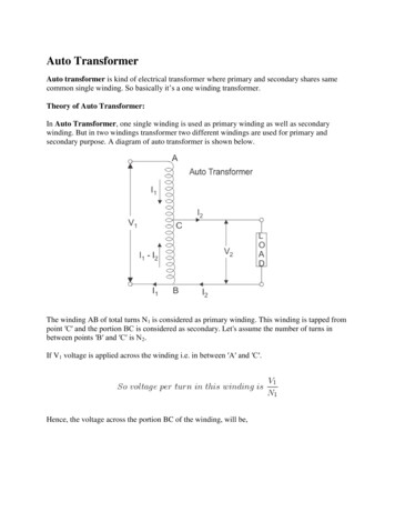
APPLICATION NOTEEffects of Transformer Construction in aMIL-STD-1553 SystemTable 1: Cross Reference of Applicable ProductsInternal PIC*Number:Product Name:ManufacturerPart NumberSMD #Device TypeSµMMIT DXESµMMIT LXEUT69151-DXEUT69151-LXE5962-9466308, 10, 11SµMMIT XTEUT69151-XTE5962-9475808MM019UT63M147 Bus TransceiverUT63M1475962-9322603, 04JB01, JB03UT63M143 Bus TransceiverUT63M1435962-0724201JB04, JB05UT63M1X5C Bus TransceiverUT63M1X5CN/AN/ABA02MM026, MM023MM025, MM027* PIC Product Identification Code1. OverviewA MIL-STD-1553 terminal consists of a transceiver and either one or two transformers depending uponwhether the terminal is configured for direct- or transformer-coupled mode of operation. Figure 1 shows atransformer-coupled terminal with an isolation transformer and coupling transformer. Transformerconstruction is an important factor to achieving optimal signal performance on the MIL-STD-1553 databus.Transformer characteristics have a direct relationship to the amplitude and degree of signal distortion. Thisapplication note discusses the importance of selecting transformers for proper signal integrity and reliability.XVR1553-AN-01BUSPoint ‘A’MIL-STD-1553TERMINALISOLATIONCOUPLINGFigure 1. Typical MIL-STD-1553 Terminal7/17/124350 Centennial Blvd. Colorado Springs CO 80907 USA 1-800-645-8862 cobhamaes.com
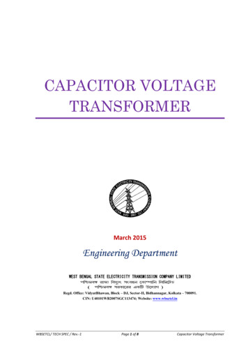
APPLICATION NOTEEffects of Transformer Construction in aMIL-STD-1553 System2. Transformer ConstructionA high-quality MIL-STD-1553 transformer should have the following characteristics: Low inter-winding capacitanceHigh coupling coefficient kPrimary and secondary inductors wound togetherWinding the primary and secondary inductors separately simplifies manufacturing but at the expense ofasymmetry of the primary windings and higher leakage inductance. Asymmetry in the windings can result insignal distortion and in poor common- mode noise rejection. A lower coupling coefficient contributes to higherleakage inductance. Both asymmetry and leakage inductance generate unwanted signal excursions that canreduce transceiver operational life expectations.The inter-winding capacitance and leakage inductance determine the frequency response of the transformer.The leakage inductance is also a significant factor to signal integrity and the resulting effects on systemreliability. The coupling coefficient, k, ranges from 0 to 1 and is a measure of the coupling of the magnetic fluxlines from the primary winding to the secondary winding. An ideal transformer will have k 1.Figure 2 shows a closed-core ferrite transformer, whose construction ensures that the magnetic flux lines arealmost entirely contained within the ferrite core with minimal leakage flux. Closed-core transformers typicallyhave a high k factor. In the case of a center-tapped primary, the closed-core ferrite transformer typicallyexhibits better symmetry between the two primary windings than is otherwise accomplished with differenttransformer constructions.XVR1553-AN-01Figure 2. Closed-core Transformer7/17/124350 Centennial Blvd. Colorado Springs CO 80907 USA 1-800-645-8862 cobhamaes.com
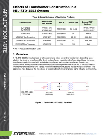
APPLICATION NOTEEffects of Transformer Construction in aMIL-STD-1553 SystemFigure 3 shows an open-core transformer. This type of construction generally results in lower coupling of themagnetic flux lines between the primary and secondary windings. The resultant leakage flux does not resultin power loss as the energy is stored in a magnetic field. However, the leakage flux appears as an inductor inseries with the primary and secondary windings. This parasitic inductor caused by the leakage flux is referredto as the leakage inductance. The primary and secondary windings of open-core transformers are oftenwound separately e.g. the primary is wound first and the secondary is wound over the primary winding. Thisresults in lower inter-winding capacitance but higher leakage inductance.Figure 3. Open-core TransformerAnother potential problem with open core transformers is the resultant asymmetry between the two primarywindings. Con- sider the schematic representation of a MIL-STD-1553 isolation transformer shown in Figure 4.Ideally, Lp1 Lp2. In a trans- former whose primary windings are imbalanced (i.e. Lp1 Lp2), unwantedsignal distortion can occur.XVR1553-AN-01The MIL-STD-1533 standard places tight restrictions on signal characteristics, such as amplitude, rise/fall time,and zero-cross distortion. A transceiver is designed to produce a signal that meets all of these requirements.However, when an imbalance exists between the two primary windings, the transceiver will attempt tocompensate for the imbalance, resulting in signal waveforms that exhibit excessive undershoot or distortion.Lp1LsLp2Figure 4. Transformer with Center-Tapped Primary Winding7/17/124350 Centennial Blvd. Colorado Springs CO 80907 USA 1-800-645-8862 cobhamaes.com
APPLICATION NOTEEffects of Transformer Construction in aMIL-STD-1553 System3. Modeling Leakage InductanceFigure 5 shows a circuit representation of a transformer with leakage inductance. The primary and secondarywindings have an inductance of L1 and L2, respectively. Due to leakage flux, k is less than 1 resulting inleakage inductances l1 and l2.l1 (1-k) L1l2 (1-k) L2The ideal transformer represents the non-lossy portion of the transformer having perfect magnetic fluxcoupling between the primary and secondary windings. Ideal transformers have a transfer function equal to(L2/L1)1/2 as shown in Figure 4.kL2kL1Ideal TransformerXVR1553-AN-01Figure 5. Circuit Representation of Transformer with Leakage InductanceIf we assume that kL1, kL2 l1, l2, then it follows that the total leakage inductance seen at the primary sideof the transformer is approximatelyl1 l2 (L1/L2)The simplified first-order circuit model is shown in Figure 6. The final model has a primary and secondaryinductance kL1 andkL2, a turns ratio of 1:(L2/L1)1/2, and leakage inductance l1 l2 (L1/L2). The primary side center tap is notshown here.l1 l2 (L1/L2)1:(L2/L1)1/27/17/12kL2kL1Ideal TransformerFigure 6. Simplified Model of Transformer with Leakage Inductance4350 Centennial Blvd. Colorado Springs CO 80907 USA 1-800-645-8862 cobhamaes.com
APPLICATION NOTEEffects of Transformer Construction in aMIL-STD-1553 System4. Asymmetry and Leakage Inductance Effects upon Signal IntegrityThe waveform shown in Figure 7 illustrates the typical signals in a system utilizing a MIL-STD-1553 isolationtransformer that has both asymmetry and high leakage inductance. The simulation model of the transformerincludes the parasitic elements and leakage inductance as shown in Figure 6. The green and red traces arethe signals directly at the output pins of the transceiver and show the undershoot that results from the nonideal transformer characteristics. The blue trace is the voltage wave- form at point ‘A’, as indicated in Figure1. Note that although there is no discernible over- and undershoot in the signal at point ‘A’, there isconsiderable undershoot in the voltage levels of the transceiver outputs. This undershoot could result in longterm reliability degradation to the transceiver if the amplitude exceeds the maximum rating of the device.XVR1553-AN-01Figure 7. Transmitted Signal at Point ‘A’ in a MIL-STD-1553 System with Finite Leakage Inductance7/17/124350 Centennial Blvd. Colorado Springs CO 80907 USA 1-800-645-8862 cobhamaes.com
APPLICATION NOTEEffects of Transformer Construction in aMIL-STD-1553 System5. ConclusionThe construction approach and quality of transformers should be a careful consideration in any MIL-STD1553 system. System designers should select high-quality transformers with good symmetry and low leakageinductance in order to meet the ac and dc requirements of the components in the system. Selectingtransformers whose primary and secondary are wound together on a closed core produces better magneticcoupling and symmetry than one whose primary and secondary are wound separately or on an open core.Failure to select transformers with proper qualities can result in lower than expected system performance andlimited mission life.No transformer has ideal coupling between its constituent windings or perfectly balanced primary windings.Therefore, there will always be some finite amount of asymmetry and leakage inductance. Designers shouldverify their design by measuring the waveforms at the transceiver pins and at point ‘A’ of the MIL-STD-1553databus to verify signal quality and compliance with the transceiver’s electrical requirements and with respectto MIL-STD-1553 performance specifications.6. ReferencesNorth Hills Signal Processing Corporation. Application Note # 151 and # 254.http://www.northhills-sp.comDixon, Lloyd H. Jr. The Effects of Leakage Inductance on Switching Power Supply 99.pdfXVR1553-AN-017/17/124350 Centennial Blvd. Colorado Springs CO 80907 USA 1-800-645-8862 cobhamaes.com
A MIL-STD-1553 terminal consists of a transceiver and either one or two transformers depending upon whether the terminal is configured for direct- or transformer-coupled mode of operation. Figure 1 shows a transformer-coupled terminal with an isolation transformer and coupling transformer. Transformer