Transcription
LECTURE 35TRANSFORMER DESIGNA.Transformer Design Preamble1. Overview of Design Complexity2. General Comments on Balancing Core and WindingLosses3. Transformer Design Constraintsa.Core Lossb. Flux Density and Absolute Number of Wire Turnsc.Copper Wire Winding Lossd. Total Transformer Loss: Core plus Coppere.Quantifing BMax or BOptf.How to find BOptg. Definition of Kgfe for the Transformer CoreB.Erickson Six Step Procedure1. Kgfe Choice2. B sat Constraint3. Absolute value for N primary4. Choose secondary turns5. Fractional Window Winding Area Allocation6. Copper Wire Area Choice:AWG#7. Check if all is consistentC. Two Illustrative Design Examples1. Cuk Converter2. Full Bridge Buck1
LECTURE 35TRANSFORMER DESIGNA. Transformer Design Preamble1. Overview of Design ComplexityWe usually place a transformer in a PWM converter circuit whereboth the electrical drive waveforms and various loads are wellknown. In the multiple-output power supply, the total currentdrawn in the transformer secondaries is I(total output current) sum of all secondary wire winding currents. P(total) of the supplyis the sum of all load powers from each secondary winding. Forlossless operation we have a rough handle of the required primarycurrent. But we will require more primary current when weinclude both core and copper losses of the transformer.We saw last time that the total power loss of a transformercan be minimized, by operating at an optimum value of BOPT(core).In this lecture we will feed this optimum B is into the total lossequations to obtain an expression for the total loss. This relationfor minimum loss then yields the transformer K parameter, Kgfe.We will employ this single parameter, Kgfe, as a guide to select theproper transformer core , just as we employed Kg to find theoptimum inductor core. Transformer losses can be put intothree major categories: core hysteresis losses, core eddycurrent losses, and wire winding losses. Core hysteresis lossesare a function of the maximum flux swing and frequency of thecurrent in the coils, whereas both wire winding loss and core eddycurrent losses depend on RMS current and flux swingsrespectively. Clearly current waveforms have a big effect onexpected transformer losses. This lecture emphasizes the losses ofpower transformers used in buck-derived topologies: forwardconverters, bridge, half-bridge, and full-wave center-tappedconverters. We will illustrate our arguments by looking first atbuck-derived circuits under the constraint of constant outputvoltage, and seeing the trends for core and copper losses. In allbuck-derived circuits that include transformers with a turns ratio n,under steady-state conditions, Vin*D n*Vo. Under fixed output2
operation as would occur with feedback, input volt-seconds andtherefore the corresponding flux swing of the transformer areconstant. We will see below that hysteresis and eddy currentlosses behave differently. Hysteresis loss is therefore constant,regardless of changes in Vin or load current. Core eddy currentloss in buck-derived operation with fixed output, on the other hand,is I2R loss in the core material, where I is induced by the changingflux versus time. If Vin doubles, Peak I2R loss in the core seems toquadruple, but since D is halved to maintain constant output,average I2R loss only doubles. Thus core eddy current lossunder these conditions is proportional to Vin. Worst case foreddy current losses occurs at high Vin. In most ferrite materialsused in SMPS applications, hysteresis losses dominate forfrequencies up to 200-300 kHz. At higher frequencies, eddycurrent losses take over, because they tend to vary with frequencysquared for the same flux swing and current waveshape. Once coreeddy current losses become significant, they rise rapidly withfrequency, especially at high Vin. Note that the increase in eddycurrent loss with high Vin and small D, is not shown in coremanufacturer’s loss curves because they assume sinusoidalwaveforms for the loss nomographs.Transformer copper winding losses in buck-derived circuitsare considered next. Primary transformer current, IP, equals load orsecondary current, IS, divided by the transformer turns ratio, n,whether peak or RMS:ISpk IL and by transformer action: IPpk IL/nNote that peak currents in the primary coil are independent ofVin. At constant peak current (constant load), rms current squared(and the copper wire I2R loss) is then proportional to duty cycle Dand inversely proportional to Vin. We assume that with constantpeak current assumed, high order harmonics depend mostly onswitching transitions and do not vary significantly with duty cycle,D, variations. This means,in buck-derived converters ,wirewinding loss is always greatest at low VIN. Thus, at frequencies3
up to 200-300 kHz, worst case is low Vin and a full load on thesecondary because of high winding losses. Winding losses alsorise with frequency, especially at low Vin. To maintain areasonable RAC/RDC, Litz wire with more strands of finer wire mustbe used. This choice may raise RDC because increased wireinsulation and voids between many stranded wires reduce theeffective copper area. Thus at frequencies where core eddycurrent losses dominate, total core loss peaks at high Vinconditions and at full load. Wire winding loss worst case alwaysoccurs at low Vin and full load. . Note the conflicting lossvariation with Vin depending on exact conditions.The above assumed ferrite cores were employed. Thesituation changes for laminated metal alloy and powdered metalcores: where core eddy current losses always dominate, henceworst case is at high Vin, full load. Winding losses are worst caseat low Vin, full load. . The trade-offs between winding and eddycurrent losses involve design compromises in the transformermaterials as well as transformer design of the wire windings.This compromise is the subject of this lecture.2. General Comments on Balancing Core and WindingAreas as well as Wire Losses:Normally, at SMPS operating frequencies, when the core isusually loss limited, not saturation limited, total transformer lossesare at a broad minimum when core losses are approximately equalto or a little less than winding losses. Previously we stated thatwinding losses are well distributed between coils by making therms current density approximately equal in all windings.However, the RMS currents will vary with the current waveformsin the individual wires. Sometimes the primary and secondarycurrent waveforms in transformers are different and as aconsequence primary and secondary currents have different RMSlevels. See pages 13-14 of this lecture for an example. You mayalso recall that the winding area allotted to each winding dependson its RMS value. With a full-bridge or half-bridge primary, withcenter-tapped secondary windings , rms current densities will be4
approximately equalized when the primary conductor cross-sectionarea is 40% and the secondaries 60% of the available area as wewill see below. In most other cases, primary and secondaryconductor areas should be 50%/50%. These 50/50n cases include:forward converters (single-ended primary/secondary SE/SE),Center-tapped primary/Center-tapped secondary transformers,bridge-half bridge primary/bridge secondary.The above wire winding allocations can be impossible toachieve because the number of turns in each winding must be anintegral number of turns. In extreme cases we find, in a lowvoltage secondary, 1.5 turns may be required for optimum balancebetween core and winding losses. With one turn, the flux swingand core loss may be much too large: with two turns the windingloss becomes too great. This kind of transformer design headachewill also be addressed herein.3. Transformer Design ConstraintsThere will be five constraints on transformer design that will resultin the formation of a transformer core K factor, Kgfe. We will usethe single factor Kgfe to guide the design process. But we mustrealize that this is a guide in the first step of an iterative processthat may require us to change our design as we go. For example,changing the number of wire turns from our first guess will alsoeffect the core choice as would a different core choice effect themaximum number of allowed wire turns.a. Core LossThis is usually found by employing a graph of total core lossprovided by the core manufacturer. To use it we need to know themaximum B field imposed on the core material.b. Flux Density and Absolute Number of Turns5
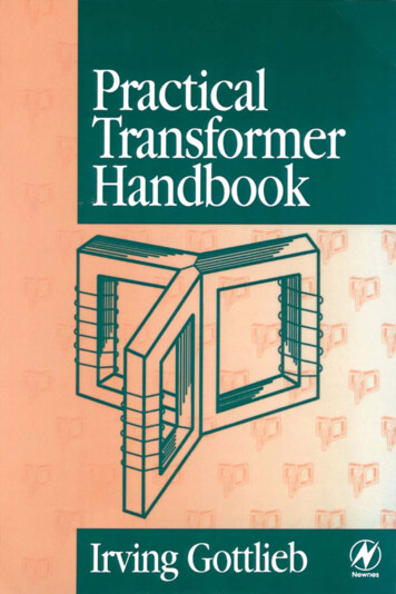
c. Copper Wire Winding LossThe key point here was made previously. Due to the allocation ofwire window area among the various windings we found thesuprising result that the resistance of the k’th winding varied asthe square of the number of turns in the k’th winding, ratherthan NK. This will be linked to the fact that n 1/B to give thetrend that wire winding loss varies as 1/B2 . This will combinewith core loss going as B to some power set by core materialschoice. Hence, an optimum B(core) exists that results in minimumoverall copper and core losses.d. Total Transformer Loss: Core plus CopperWe saw previously that P(copper) goes as N2 which is the same as6
1/B2. We also know P(core) goes as B, so the total loss versus Bhas a broad minimum as shown below.e. Quantifying BMAX or BOPTTo optimize any function we take the derivative and set it equal tozero, taking care to insure the sign of the second derivative ispositive for a maximum. This will give us an expression for BOPTin terms of all the transformer design parameters, both for thewindings and the core. We then place this value of BOPT into thetotal power expression to find the transformer K factor, Kgfe.7
f. We outline below how you find BMAX or BOPTThis will be a simple mathematical exercise as shown below.This expression is just the mid-point of the calculation. We nextplug BMax into the total power loss in the transformer includingboth copper and core losses as shown on page 8 and solveexplicitly for the minimum total power loss including both coreand copper losses.8
g. Definition of Kgfe for the TransformerWe are now equipped with our single transformer K factor,Kgfe, to go forth and follow a step-by step transformer designprocedure as given below.B. Erickson Six Step Procedure toTransformer Design:Step 1Material Choice for the Core:KgfeWe determine the required core size from the Kgfe constant of thechosen core material. We need the wire current required by thecircuit, the required total power level and flux linkage values orprimary volt-sec specification from the input voltage to thetransformer waveform. To make sure the units are consistent in9
the Kgfe parameter we list below the major transformer quantities.Now we are on the same page for calculating Kgfe.Kgfe β)ρ λ12 I2tot K(2/fe(( β 2)/ β )1084 K u ( P tot )The core data base spec’s Kgfe for various generic sizes is inAppendix 2 of Erickson. We use Kgfe to pick the appropriate coresize and core material such that we meet this inequality. P We assume ρeff ρcu cu Pdc If by different core materials choice Kfe this allows us to employa smaller core for the job and vice versa.Step 2BSat Constraint due to core propertiesEvaluate peak flux density and compare to Bsat of the chosen corematerial that we decided to employ. B max 10 2 28 ρ λ1 I tot2 Ku((MLT)1 W A A 3c l e β K fe 101)β 2
Bmax must be below Bsat! For pure AC excitationV(peak) NpAcw B(sat) or Vp/NAcw B(sat)Note both Kgfe and Bmax both vary as the volt-sec quantity λ21. Becareful to note any DC core flux bias effects due to amp-turneffects. If at this point we exceed BSAT we need to either of twopaths in an iterative approach:1. Choose a core with a BIGGER Kfe loss factor and repeatthe first two steps.2. For HW#1 YOU SUGGEST ANOTHER SOLUTIONStep 3Absolute Number of TurnsEvaluate the absolute number of required primary turns from thepreviously calculated Bmax.Note: λ1 vdt , when the fsw then λ1 for a fixed V.fsw what happens to core loss.λ1n1 1042 Bmax A cHaving specified the turns on the primary the secondary turnsfollow the voltage ratios of the various secondary voltages.Step 4 Secondary TurnsChoose the numbers of turns for other windings according to thedesired turns ratios: n2 n2 n1 n1 n3 n3 n1 n1 Restrictions on Number of TurnsChoices regarding the number of turns and turns ratios areoften severely limited by low voltage secondaries because integralnumber of turns must be used. For example in a 5 Volt output thealternatives might be a 1-turn or a 2-turn secondary. This changerepresents a 2 to 1 step in the number of turns in the primary. For11
the same size core and this change doubles the current density inthe windings and accordingly increases the loss.Choices may be further restricted when there are multiplelow voltage secondaries. For example a 2.5 to 1 turns ratio may bedesirable between a 12 Volt and a 5 Volt output. This is easi1yaccomplished with a 2-turn 5V secondary and a 5-turn 12Vwinding. But if the 5V secondary has only 1 turn, the only choicefor the 12V secondary is 3 turns, which may result in excessivelinear post-regulator loss. This problem could be handled by theuse of fractional turns but this has it’s own hazards.There are no hard and fast rules to follow in establishingthe optimum turns for each winding, but there is some generalguidance. First define the ideal turns ratios between windings thatwill achieve the desired output voltages with the normal VinDestablished earlier. Later, when a specific core has been tentativelyselected, the turns ratios will translate into specific turns, but theseare not likely to be the integral numbers required in practice. Itthen becomes a juggling act, testing several approaches, beforereaching the best compromise with integral turns. The lowestvoltage secondary usually dominates this process, because withsmall numbers the jumps between integral turns are a largerpercentage. Especially if the lowest voltage output has the greatestload power, which is often the case, the lowest voltage secondaryis rounded up or down to the integral. Rounding down willincrease core loss, up will increase winding loss. If the increaseloss is unacceptable, a different core must be used that will requireless adjustment to reach an integral number of turns. The lowvoltage output is usually regulated by the main control loop.Higher voltage secondaries can be rounded up to the next integralwith less difficulty because they have more turns. However, it isunlikely that accuracy or load regulation will be acceptable,requiring linear or switched post-regulation. Since in practice theprimary is usually higher voltage, the primary turns can usually beset to achieve the desired turns ratio without difficulty.12
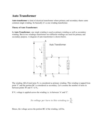
Once the turns have been re-established, the initialcalculations must be redefined. Don’t forget this is iterative designproceedure.Step 5 Allocation of Wire Winding WindowEvaluate the fraction of window area allocated to each windingbased upon the ratio of the mmf’s or amp-turns of each windingcompared to the primary amp-turns .n1 I1α1 n1 I totα2 n 2 I2n1 Itotnk I kn1 I totA more quantitative example here would be useful and is givenbelow. Consider the Full Bridge PWM Converter TransformerCase of page 13. The three transformer windings each have uniquecurrent versus time waveforms due to the center-tapped secondaryand the circuit switches, so that RMS values of the primarycurrent, i1 and secondary currents, i2 and i3, are quite different.This will effect the allocation of the wire areas in the wire windingwindow,WA, in ways you might not anticipate. This is mostevident from the current versus time waveforms.αk 13
Consider the primary winding first and its proper relative areaof windings in the core window.1N1 I1 α1 N IN IN1 I1 N 2 I2 N 3 I31 2 2 3 3N1 I1N1 I11I 1 DN21 1 DN IN 2 I22 same for 3 3 N22DN1 I1N1 I1I DN1N11α1 1 D1 DPrimary wiring area is a function of the expected DC operatingchoice for duty cycle f1(D)11α2 α3 2D1 1 DSecondary areas are equal and also depend on the chosenequilibrium duty cycle f2(D)14
Step 6 Wire AWG # AssignmentsEvaluate and choose proper copper wire sizes to equalize ρJ2losses in each winding.α 2 K u WAA w1 n1α 2 Ku WAAw 2 n2Choose wire gauges to satisfy these criteria.Step 7 CHECK OF RESULTS: Need for IterationNow we can check the transformer parameters calculated above.The multi-winding transformer has one Lm as seen in the primarycircuit and many winding resistance’s. Let’s take the threewinding transformer shown on the top of page 12 and calculate LM,IM(peak) and the resistance’s in the various wire windings. Wewill not attempt to calculate the leakage inductance’s of the variouswindings. For extra credit on HW#1 try to outline themethodology to do so.N 2pLm Rpµ c N 2p A c leλ1 vdt i m (peak) 2 L m 2 LmWinding resistances:15
R1 R2 ρ n1 (MLT)Aw1ρ n2 (MLT)Aw 2D. TWO ILLUSTRATIVE DESIGN FLOWEXAMPLES1. Illustrative Single -output CuK Converter With IsolationTransformer Design:We are given: fsw 200 kHz; Dop 0.5, Ku 0.5,P 100W , aturns ratio n 5 and we allow only a total loss in the transformer of0.25 W. We seek a 5 V output from a 25 V input switched at 200kHz. The total circuit power is 100 W P(total) causing Iin 4Aand Iout 20 A.This sets the quiescent duty cycle to D 0.5 for the givenntransformer turns ratio is 1 5 .n2For the chosen core material spec’s we have:WK fe 24.7 β 3 , β 2.6 FerriteT cmFor the chosen wire to be used for windings we have:The total flux linkage in the transformer core is given in V-µs.16
λ1 D Ts Vc1 1(5µ S)25V 62.5 V-µS2From the Appendix of rms values the I1(rms) from the I1 waveformgiven below is:In12 5I1 (rms) D( 2 ) D ' (I g ) 4 A ; Where n nn2We also know that I2 (rms) n I1 (rms) 20 A nI1(rms)Now we sum the volt-sec current and the load current in theprimary to find: I total I1 I2 / n 8 A (rms)Now we know I(total), P(total), λ1, Kfe, β, Kcu so that Kgfe may beestimated.17
Kgfe (1.724 10-6)(62.5 10-6 )2 (8)2 (24.7 )(2/2.6)108 0.0034(0.5)(0.25)(4.6/2.6)Go to appendix 2 in Erickson on cores and match Kgfe to a standardcore #. We choose #2213 to match Kgfe .0047 as close aspossible. The next smallest core is not sufficient. This exceeds thecalculated Kgfe required 0.003 and will provide lower core loss vialower Bmax. Having chosen core #2213 we know from the corespecs AC(core), WA and the mean length of wire turn (MLT) toencircle the core. Thus we know Bmax.(1/4.6)Bmax (1.724 10-6)(62.5 10-6 )2 (8)2 (4.42)1 32(0.5)(2.6)(24.7)(0.297)(0.635)(3.15) 0.0858 TeslaBmax is indeed Bsat for the chosen core material which is given 0.35 Testla. In general, BSAT for ferrites that operate around100kHz is typically 0.1 Testla Knowing B(max), λ1, and Ac wecan calculate the number of turns N1 required to keep φ(max) B(sat).λ1 * 104 5.7 turns we arbitrarily choose N1 5 and N2n1 2 B max A cN 1, n2 1 1.0 This round-off direction choice leads to5slightly higher B and higher core loss, which we judge isacceptable.Fractional wiring windowsNext we determine the fraction of the core wiring window thateach winding will occupy α 1 (4 A) 0.5 of the available wire(8 A)winding area18
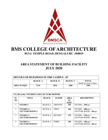
1( )(20A)5 0.5 of the available wire winding areaα2 (8A)This allows us to then calculate the required copper wire sizes.(0.5)(0.5)(0.297) 14.8 10-3 cm2 For the primary or 5 turnsAw 1 (5)of #16AWG copper wire(0.5)(0.5)(0.297) 74.2 10-3 cm2 For the secondary or againAw 2 (1)one turn of #9AWG copper wire, which is not practical. Somepractical solutions are to use Litz wire, or to use foil wires.Note the trends for the core size for the Cuk converter, given thecore parameters as fixed by our choice of core material, as wechange the switch frequency:From λ1 vdt f sw λ1 Βοth Bmax and im . Thischanges required abcd core diameter as shown below for core sizevs fsw.Bmax fasterdue tocoreloss!Below 0.25 MHzAbove 0.25 MHzWhen f then the When f thencore size core size Conclude: f allows smaller core UNTIL inherent core loss of the19
material system kicks in at higher f. We thus can only reducetransformer size in this specific case only over a limited f rangeby increasing fsw . With different circuit waveforms and differenttransformer materials these core size trends would be altered orshifted.2. Illustrative Full Bridge Buck Transformer Design:Bop 0.75See Section 6.3.1, Pg. 141 of Erickson’s text for details of switchtiming. For a given switch frequency,fs 150 kHz then Ts 6 2/3µs 6.66 µs. However, the transformer frequency is not theswitch frequency. Below we review design high lights.Interval#1Q1Q4 AllD5D6Q2Q3 D6D8AllD5D6Q off D7D8ononQ offD7D8offoffBridge occurs operation in transformer secondary and due to centerftaping we find f(trf) f sw . Consider the core choice as2made with a core of known properties as summarized on the top ofpage 20.20
Ferrite: At 75 kHz we find for the core materialW, β 2.6K fe 7.6 β3T cmWe have chosen to utilize an”E-E” type geometery core for thistransformer. Consider also that the wire choice was made so thatKu(fill factor) 0.25 (Litz wire).P(total transformer loss) is fixed at 4W for both core and allwire winding by the temperature constraints and thermalequations.K gf e λ12 I 2 (total) Both of which are presently known.We need to find λ1 of the primary winding and I(total) in order toselect a core from manufacturers tables with a GREATER Kgfethan our calculation gives.The flux-linkage λ Nφ V t VDTs is obtained from V1(t)waveforms, shown below,as:λ1 (0.75)(6.66µs) 160V 800 V-µsecGiven the i1(t) waveform versus time we can calculate I1(rms)I1 (n2/ n1 I(5V winding) n3/n1 I(15V1/2winding)D . This becomes I1rms IpD1/2 from appendix I1rms 5.7We plot on page 20 the secondary current waveforms versus timeand calculate the RMS values of the currents.21
Given the i2(t) waveform we can calculate I2(rms)I2rms (I 5V/2) (1 D)1/2 66.1 AGiven the i3(t) waveform we can calculate I3(rms)I3rms (I 15V/2) (1 D)1/2 9.9 AKnowing all currents in all windings we can find:n3n2I 3 14.4 A ;I total (rms) I1 I2 2n1n1515Where n2/n1 and n3/n1 110110(1.724 10-6)(800 10-6 )2 (14.4 )2 (7.6)(2/2.6)8 .0094Kgfe 104(0.25)(4 )(4.6/2.6)From the appendix 2 of Erickson we select for the windings theEE40 core that just meets the Ptotal and Itotal spec’s. Kgfe(EE40) 0.01 .009; gamble (it will be too close a guess!) But lets seewhat happens.22
For this core geometry we find the geometric factors le 7.7, Ac 1.27, WA 1.1, and MLT 8.5:(1/4.6) 8 (1.724 10-6)(800 10-6 )2 (14.4 )2 (8.5)1Bmax 10 2(0.25)(1.1)(1.27 )3 (7.7) (2.6)(7.6) 0.23 TeslaBmax 0.23 is well below Bsat 0.35 for the core materialWe can specify n1 to insure no saturation occurs.λ1 * 104 13.7n1 2 Bmax A cWhere we used Ac 1.27 and λ1 800 *10-6513.7 0.62n2 1101513.7 1.87n3 110Now round off to total of fractions in an artfulway: n1 22, n2 1, n3 3.Given the new n1 from the round-off recalculate Bmaxλ1 0.14 TeslaBmax 2 n1 A c1P(loss) Pcore (Bβmax) Pcu wire ( 2 )BmaxWe take these terms one at a time. Core volume Ac*le.Note also Kfc 7.6, Bm 0.143, Ac 1.24 and le 7.7 so that:P core K fe B max A c le 0.47 WAt 20 C ρ(Cu) 1.7*10-6, λ1 800*10-6, I(total) 14.4, MLT 8.5,WA 1.1 and Ac 1.24.23
ρ λ12 I 2totMLT108 5.4WP cu 4 kuW A A 2cB2maxFor the full-bridge use of the core we find that the total core loss is:P(total) 0.47 5.4 6WUnfortunately the core is only specified for Ptotal 4W Lost ourgamble of pg. 20. We actually Need larger core to dissipate thehigh energy.Our next iterative choice EE50 has Kgfc .028, Bmax 0.14 withn 12Keeping n1 22, n2 1, n3 3Bmax(n1 22) .08TPtotal Pcore(0.8T) Pcu wire(0.8T) 0.23 3.9 } now the corechoice appears consistent ok.Next we allocate areas for the individual windings.One Primary Winding Areaα1 I1 0.396 of availableITTwoSecondary Winding Areasα2 N2I2 / IT 0.21N1α3 N2I2 / IT 0.09N1Next wire we specify the AWG #’s of the three windings(0.396)(0.25)(1.78)α 1 K u WA 8.0 10-3 cm2Aw 1 (22)n1 AWG #19 for the primary24
(0.209)(0.25)(1.78)α 2 K u WA 93.0 10-3 cm2 (1)n2 AWG #8 for the 5 V secondary winding(0.094)(0.25)(1.78)α 3 K u WA 13.9 10-3 cm2 Aw 3 (3)n3 AWG #16 for the 15 V secondary winding. Of course we couldalso use Litz wire or foil for the secondary windingsAw 2 Start to read Chapter 5 of Erickson this week as we will finishpower magnetics and transformers next lecture. Lecture 37 willstart discontinuous conduction mode.25
TRANSFORMER DESIGN A. Transformer Design Preamble 1. Overview of Design Complexity We usually place a transformer in a PWM converter circuit where both the electrical drive waveforms and various loads are well known. In the multiple-output power supply, the total current drawn in the transformer secondaries is I(total output current)