Transcription
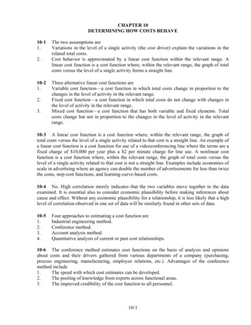
DOI: 10.3933/APPLRHEOL-25-42670 WWW.APPLIEDRHEOLOGY.ORGSimple Method for Determining Stress and Strain Constants forNon-standard Measuring Systems on a Rotational RheometerJohn J. Duffy*, Adrian J. Hill, and Shona H. MurphyMalvern Instruments Ltd, Enigma Business Park, Malvern, WR14 1XZ, United Kingdom* Corresponding author: john.duffy@malvern.comReceived: 6.2.2015, Final version: 8.5.2015Abstract:There is often a necessity to measure, or at least estimate, true viscosity values using non-standard measuring systems on arotational rheometer. This may be to replicate a mixing or manufacturing process on a lab scale, to keep a sample dispersedand uniform during a measurement or to measure some rheological property that would be difficult or impossible with a standard configuration. Such measurements can be made easily enough, but without a process for converting torque to shearstress and angular velocity to shear rate only these raw data variables can be reported. In this paper a simple and novel empiricalmethod for determining strain/strain rate C1 and stress C2 constants for non-standard measuring systems on a rotationalrheometer is presented. This method uses relative torque measurements made with a Newtonian and non-Newtonian materialand their corresponding power law fitting parameters to determine C1 and C2 using a non-linear regression analysis. Equilibriumflow curves generated for two non-Newtonian fluids using two non-standard mixing geometries show very good agreementwith data generated using a standard cone and plate configuration, therefore, validating the approach.Key words:Measuring system constant, true viscosity, torque, mixer, angular velocity, shear rate factor1INTRODUCTIONTo measure shear viscosity accurately using a rotationalrheometer it is important that the flow field is homogenous and laminar and the shear rate is well defined. Forthis to be the case the shear gap needs to be small(based on the sample being measured) and linearlydependent on the velocity at the shearing surface. Suchconditions are met in the case of ‘cone and plate’ measuring systems, so long as the angle between the plateand cone is small, because any increase in linear velocitywith cone radius correlates with an equivalent increasein shear gap. The working equations for cone and plateare shown below (Equations 1 and 2) with ω the angularvelocity, θ the cone angle, τ the torque, and R the radiusof the cone.(1)For a ‘parallel plate’ system the linear velocity increaseswith radius, but since the gap remains constant the shearrate then varies across the radius of the plate [1] as illustrated in Figure 1. This does not matter too much for Newtonian liquids since both shear stress and shear rate arelinearly related, and hence viscosity is constant, however,for non-Newtonian liquids the shear stress has a non-linear dependence and the viscosity will thus vary at different radial locations. This can be largely corrected for byapplying a non-linear correction based on the local power law index n [1] or by calculating the viscosity at ¾ ofthe plate radius instead of the edge, since the shear ratefor non-Newtonian and Newtonian materials have comparable values close to this point [2]. The working equations for parallel plates are given below (Equations 3 and4) based on shear rate calculation at the plate edge andwith non-linear corrections applied for shear stress. Toimplement the single point correction, one just assumesa Newtonian response (n 1) with the resultant valuesor equations for g· R and s multiplied by a factor of ¾.(3)(2) Appl. Rheol. 25 (2015) 42670 DOI: 10.3933/ApplRheol-25-42670 1
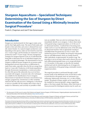
Figure 1: Schematic showing stress distribution across a parallel-plate for Newtonian and pseudoplastic fluids havingequivalent viscosity at ¾ R.(4)Both the single point method and power law correction methods can give slight errors compared withmeasurements made on a cone-plate configuration,especially in the transition region between Newtonianand non-Newtonian behavior. For the single point correction the radial position at which measured stressesare equivalent for Newtonian and non-Newtonianmaterials can shift slightly from the ¾ position, whilefor the power law method, estimation of n by local differentiation of the torque vs angular velocity data canbe another source of error. Similar issues exist for ‘coaxial cylinders’ since shear stress and shear rate decreasewith radial distance from the surface of the rotatinginner cylinder, with shear rate showing a non-lineardependence for non-Newtonian materials. In this caseerrors are minimised by using a small gap and assuminga linear profile across the gap, while for large gaps anon-linear correction needs to be made [1, 4]. An additional ‘end-correction’ also has to be made to accountfor any additional shear at the base of the moving innercylinder [4].For each of the above measuring systems a strainconstant C1 and stress constant C2 can be assignedbased on the dimensions of the measuring system andthe size of the shearing gap. By multiplying by therespective constant the applied or measured torque canbe converted into shear stress, the angular displacement in to shear strain and the angular velocity in toshear rate, with any non-linear corrections requiringthe power law index n usually applied afterwards. Thesituation gets more complicated for non-standardgeometries such as mixers and even regular geometriessubmersed in a sea of fluid, since the shear rate variesin both the axial and radial directions and the shearstress may not be well defined. For such systems thebest one can hope to attain is an average shear rate anda corresponding shear stress such as to give similar viscosity shear rate profiles to those attained with standard geometry configurations such as narrow gapcoaxial cylinders or cone and plate.Various methods exist for estimating stress andstrain constants for these geometries some of whichhave a theoretical basis and others empirical. Oneempirical method referred to as the ‘viscosity matchingmethod’ is based on a procedure designed for estimating the viscosity in mixing vessels. Here power measurements or the corresponding torques can be used toestimate the viscosity of Newtonian and non-Newtonian materials at a particular mixing speed, corresponding to an average shear rate. The viscosity is then compared with a flow curve generated on a rotational rheometer to determine the shear rate at which the viscosityis of equivalent magnitude. This method was utilisedby Otto and Metzner [5] to determine the shear raterange in a mixing vessel and by Wood and Goff [6] toestimate the average shear rate in the Brabander Viscograph. In a later paper Rao and Cooley [7] referred tothis method as the Metzner-Otto-Wood-Goff (MOWG)method. Another method developed by Rieger andNovak [8] uses the relationship between the powernumber P and power law index n associated with a mixer to determine a value for the rpm-shear rate conversion factor k1 since P k1(n-1). By measuring the powerinput required to agitate several power law fluids, k1 canbe determined graphically. This method was used byRao [9] to determine the effective shear rate of a flagimpeller and later referred to this method as the RNmethod to distinguish from the MOWG methoddescribed previously.Castell-Perez and Steffe [10] showed that a constant value of the mixer proportionality constant k1 wasnot valid for all types of rheological fluids and wasdependent on relative dimensions of the cup and mixeras well as the rotational speed. In a later paper Castell-Perez et al. [11] used a mathematical approachbased on the analogy of a power-law fluid in a concentric cylinder system to determine the shear rate andshear stress for a paddle system without the need forstandard calibration fluids, which showed good agreement with measurements made on a rotational rheometer. Bousimina et al. [12] derived a model based onthe empirical method of Goodrich and Porter [13] fordetermining the shear rate and viscosity in a batch mixer using an equivalent cylinder principle. This requiresestimating the internal radius of an equivalent concentric cylinder system that gives the same torque as themixer system at an equivalent rotation rate. This principle has also been used by Aerts and Verspaille [14] toproduce flow curves from a Brabander Viscograph andboth studies showed good agreement with rheometerdata. A separate numerical method was derived byWilliams [15] for determining true viscosity-shear ratedata for a rotating disk in a sea of fluid based on a Brookfield viscometer. Appl. Rheol. 25 (2015) 42670 DOI: 10.3933/ApplRheol-25-42670 2
There is clearly a necessity to measure, or at leastestimate, true viscosity values using non-standardmeasuring systems as evidenced from the studies andapplications cited previously. This may be to replicate amixing or manufacturing process on a lab scale, to keepa sample dispersed and uniform during a measurementor to measure some rheological property that would bedifficult or impossible with a standard configuration.Such measurements can be made easily enough, butwithout a method for converting torque to shear stressand angular velocity to shear rate only these raw datavariable can be presented. The purpose of this paper isto propose and discuss a simple empirical method thatcan be performed with a rotational rheometer to estimate the shear stress and shear rate for non-standardmeasuring systems. The proposed method is not toodissimilar to some of those cited previously but is muchsimpler and requires fewer experimental steps thaneither the RN or MOWG methods. The procedure isbased on Equation 5 which has previously been used toestimate power law parameters for a simple mixerusing measured torques and angular speeds [16]. Thissame equation can, however, be used to determine theproportionality constant between angular velocity andshear rate C1 if the power law parameters K (consistency) and n (power law index) are known for a standardNewtonian fluid (denoted by the subscript N) and nonNewtonian fluid (denoted by the subscript P). The power law index n is 1 for a Newtonian liquid so does notappear in Equation 5.(5)By making torque measurements with a non-standardgeometry at a defined angular velocity in both the Newtonian and non-Newtonian fluid fluids (under laminarflow conditions), the relative stress value sP/sN can beestimated from the torque ratio τP/τN. Inputting thisvalue along with the power law parameters KN, KP, andn into Equation 5 leaves just one unknown, which is C1.This equation can then be solved using a non-linearregression analysis with the objective to minimise theresidual between the calculated relative stress (sP/sN)and the measured relative torque (τP/τN) by iterativelychanging C1 until an optimum solution is found. A keybenefit of this approach is that the value determinedfor C1 is optimised for both Newtonian and non-Newtonian materials since the optimization method usesdata generated for both fluid types to find a solution.This is effectively the same as locating the radial position on the parallel plate where the shear stress is equiv-alent for a Newtonian and non-Newtonian material ata given shear rate. Once C1 has been determined thisvalue can be substituted in to Equations 6 and 7 todetermine individual values for sP and sN.(6)(7)The corresponding proportionality constant C2 , required to convert torque to shear stress, can then bedetermined from Equation 8 by inputting sP or sN andtheir corresponding torques τP and τN. Both sets of values should yield similar values of C2 if an optimised value for C1 was found from the non-linear regressionanalysis, however, an average of the two values shouldbe used to give a single optimum value of C2 .(8)It should be noted that constants generated by thismethod will only be relevant for the particular measuring configuration and fluid volume used to determinethem. The measurement process can be summarised asfollows:n Determine power law constants for a Newtonian oil(1 Pas oil) and a power law fluid (hair gel or bodylotion) by making measurements with a suitablecone and plate geometry and fitting a power lawmodel to the data. A higher viscosity fluid will minimise turbulence in the proceeding step.n Measure the steady state torque for each fluid at anequivalent angular velocity (1 rad/s) using the uncalibrated geometry in the appropriate vessel,ensuring the correct gap and same fill volume areused for both measurements.n Perform a non-linear least square analysis with theobjective to minimise the residual between the calculated relative stress sP/sN and the measured relative torque τP/τN by iteratively changing C1. Thiscan be performed with the Solver Tool in MicrosoftExcel, employing the Generalized Reduced Gradient(GRG) Nonlinear analysis function [16] or anothertechnical computing software package.n Calculate sP and sN by substituting in to Equations6 and 7 and divide by τP and τN respectively as indicated by Equation 8 to give two values for C2 andtake the mean. Appl. Rheol. 25 (2015) 42670 DOI: 10.3933/ApplRheol-25-42670 3
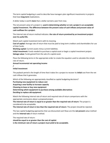
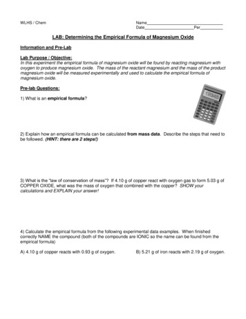
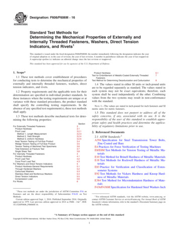
Figure 2: Photographs of the Mixer A (above) and Mixer B(below) used in this study.2MATERIALS AND METHODSTwo non-standard mixing geometries Mixer A and Mixer B were used in this study, both connected to a stainless steel shaft as shown in Figure 2. To determine thestress and strain constants for these systems a commercial body lotion was employed as a standard powerlaw fluid and 1 Pas oil as a standard Newtonian fluid. Allmeasurements were made using a Kinexus Pro rotational rheometer (Malvern Instruments) at a temperature of 25 C. The power law parameters for each ofthese fluids were determined using an equilibriumtable of shear rates test with a 4 /40 mm cone and platemeasuring system then fitting a power law model tothe resultant data to determine values of K and n. Forthe body lotion K was determined to be 28.7 and
in shear gap. The working equations for cone and plate are shown below (Equations 1 and 2) with ωthe angular velocity, θthe cone angle, τthe torque, and Rthe radius of the cone. (1) (2) Simple Method for Determining Stress and Strain Constants for Non-standard Measuring Systems on a Rotational Rheometer John J. Duffy*, Adrian J. Hill, and Shona H. MurphyFile Size: 408KBPage Count: 6