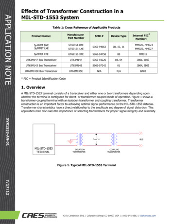
Transcription
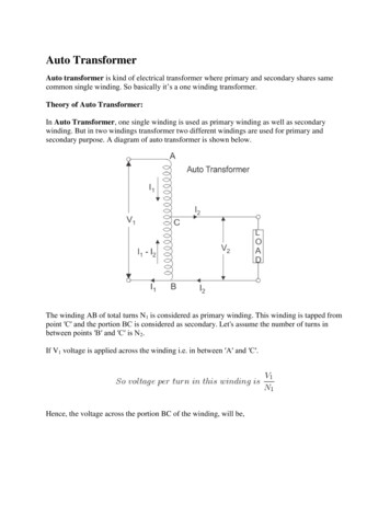
Auto TransformerAuto transformer is kind of electrical transformer where primary and secondary shares samecommon single winding. So basically it’s a one winding transformer.Theory of Auto Transformer:In Auto Transformer, one single winding is used as primary winding as well as secondarywinding. But in two windings transformer two different windings are used for primary andsecondary purpose. A diagram of auto transformer is shown below.The winding AB of total turns N1 is considered as primary winding. This winding is tapped frompoint ′C′ and the portion BC is considered as secondary. Let's assume the number of turns inbetween points ′B′ and ′C′ is N2.If V1 voltage is applied across the winding i.e. in between ′A′ and ′C′.Hence, the voltage across the portion BC of the winding, will be,
As BC portion of the winding is considered as secondary, it can easily be understood that valueof constant ′k′ is nothing but turns ratio or voltage ratio of that auto transformer.When load is connected between secondary terminals i.e.between ′B′ and ′C′, load current I2starts flowing. The current in the secondary winding or common winding is the difference of I2& I1.Copper Savings in Auto TransformerNow we will discuss the savings of copper in auto transformer compared to conventional twowinding transformer.We know that weight of copper of any winding depends upon its length and cross - sectionalarea. Again length of conductor in winding is proportional to its number of turns and cross sectional area varies with rated current.So weight of copper in winding is directly proportional to product of number of turns and ratedcurrent of the winding.Therefore, weight of copper in the section AC proportional to,and similarly, weight of copper in the section BC proportional to,Hence, total weight of copper in the winding of auto transformer proportional to,
In similar way it can be proved, the weight of copper in two winding transformer is proportionalto,N1I1 N2I2 2N1I1(Since, in a transformer N1I1 N2I2)Let's assume, Wa and Wtw are weight of copper in auto transformer and two winding transformerrespectively,
Saving of copper in auto transformer compared to two winding transformer,Auto transformer employs only single winding per phase as against two distinctly separatewindings in a conventional transformer.Advantages of using Auto Transformers1. For transformation ratio 2, the size of the auto transformer would be approximately 50%of the corresponding size of two winding transformer. For transformation ratio say 20however the size would be 95 %. The saving in cost of the material is of course not in thesame proportion. The saving of cost is appreciable when the ratio of transformer is low, thatis lower than 2. Thus auto transformer is smaller in size and cheaper.2. An auto transformer has higher efficiency than two winding transformer. This is because ofless ohmic loss and core loss due to reduction of transformer material.3. Auto transformer has better voltage regulation as voltage drop in resistance and reactance ofthe single winding is less.Disadvantages of Using Auto Transformer1. Because of electrical conductivity of the primary and secondary windings the lower voltagecircuit is liable to be impressed upon by higher voltage. To avoid breakdown in the lower
voltage circuit, it becomes necessary to design the low voltage circuit to withstand highervoltage.2. The leakage flux between the primary and secondary windings is small and hence theimpedance is low. This results into severer short circuit currents under fault conditions.3. The connections on primary and secondary sides have necessarily needs to be same, exceptwhen using interconnected starring connections. This introduces complications due tochanging primary and secondary phase angle particularly in the case of delta / deltaconnection.4. Because of common neutral in a star / star connected auto transformer it is not possible toearth neutral of one side only. Both their sides should have their neutrality either earth orisolated.5. It is more difficult to maintain the electromagnetic balance of the winding when voltageadjustment tappings are provided. It should be known that the provision of tapping on anauto transformer increases considerably the frame size of the transformer. If the range oftapping is very large, the advantages gained in initial cost is lost to a great event.Applications of Auto Transformers1. Compensating voltage drops by boosting supply voltage in distribution systems.2. Auto transformers with a number of tapping are used for starting induction and synchronousmotors.3. Auto transformer is used as variac in laboratory or where continuous variable over broadranges are required.
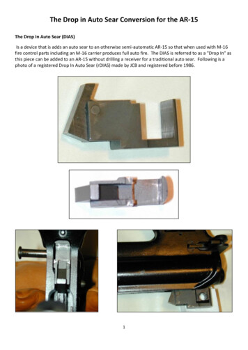
Welding transformer working principle and applicationIntroductionA welding transformer is a step down transformer that has thin primary winding with a largenumber of turns and its secondary has more area of cross-section and less number of turnsensuring less voltage and very high current in the secondary. The welding transformer reducesthe voltage from the source voltage to a lower voltage that is suitable for welding. Usuallybetween 15 and 45 volts. The secondary current is quit high and it may be typically 200A to600A, but it could be much higher. The secondary may have several taps for adjusting thesecondary voltage to control the welding current. The taps are typically connected to a severalhigh-current plug receptacles or to a high-current switch. One end of the secondary is connectedto the welding electrode, whereas the other end of the secondary is connected to the weldingelectrode, whereas the other end is connected to the pieces to be welded .If any high currentflows, heat is produced due to the contact resistance between the electrode and the pieces to bewelded. The generated heat melts a trip of the electrode and the gap between the two pieces isfilled. Figger shows a simple welding transformer.The impedance of welding transformer may be higher than that of the impedance of a generalpurpose transformer. The impedance of welding transformer may play a role in the process ofestablishing an arc and controlling the current. Large welding transformers are most likely to bedesigned for three phase input. There are many smaller transformers that are designed for singlephase input.
DC welding transformerFor welding with direct current (DC) a rectifier is connected to the secondary of the transformer.There may also be a filter choke or an inductor to smooth the DC current. the entire transformerand rectifier assembly may be called a welding power supply. The winding used for the weldingtransformer is highly reactive. Otherwise, a separate reactor may be added is series with thesecondary winding.ARC control of welding transformerTo control the Arc ,various reactors are used with welding transformers. Some methods tocontrols the arc are given below.Tapped ReactorWith the help of taps on the reactor, the output current is regulated. This has limited number ofcurrent settings.Moving Coil reactorA moving coil reactor is one in which the reactive distance between primary and secondary isadjusted. The current becomes less if the distance between the coils is large.Moving shunt reactorA moving shunt reactor is one in which the position of the central magnetic shunt can beadjusted. Change of the output current is obtained due to the adjustment of the shunted flux.Continuously variable ReactorA continuously variable reactor is one in which the height of the reactor is continuously varied.Greater reactance is obtained due to greater core insertion and hence the output current is lessSaturable reactorTo adjust the reactance of the reactor, the required DC s
aturation if the DC excitation current is more. Therefore, changes of current are obtained due tothe change o reactance
same proportion. The saving of cost is appreciable when the ratio of transformer is low, that is lower than 2. Thus auto transformer is smaller in size and cheaper. 2. An auto transformer has higher efficiency than two winding transformer. This is because of less ohmic loss and core loss due to reduction of transformer material. 3.