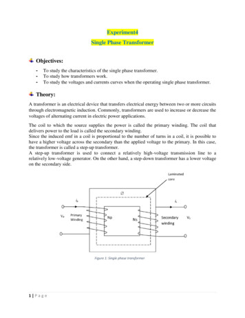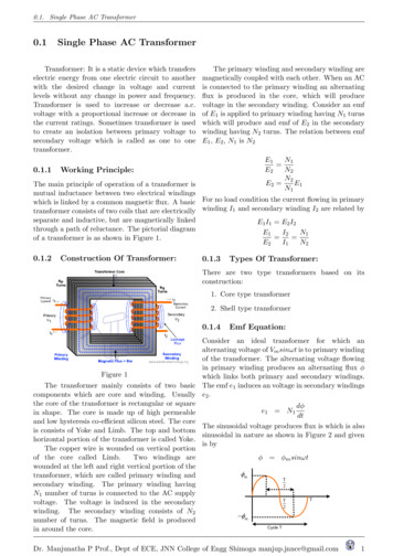
Transcription
Experiment 2Single Phase Transformer (I)Objectives To determine the turns ratio of a single phase transformer.To determine the parameter values of the excitation branch that model the core and magnetizationlosses in a real transformer.To determine the parameter values of components that model the copper losses and leakage flux in areal transformer.Turns Ratio TestIntroductionFrom Figure 2.1 the turn’s ratio of a single phase transformer is defined as the ratio of the primarywinding voltage V1 to the secondary winding voltage V2 when no load is applied as followa V1 VP V2 VS(2.1)ipisNsNp vvsp-ipisNsNp v vsp--Figure 2.1: Schematic symbol of a transformerIn an ideal transformer, there is no leakage in the magnetic field (Φ) flowing through the iron core andsince Faradays law states that "If a flux passes through a turn of a coil of wire, a voltage will be inducedin the turns of wire that is directly proportional to the rate of change in the flux with respect to time" sothateind -Ndφdt(2.2)then, it is clear that dφ V1 V2 dt N1 N 20405344: Electrical Machines for Mechatronics Laboratory(2.3)2–1
Experiment 2Single Phase Transformer (I)thusa V1 N1 V2 N 2(2.4)Moreover, the apparent power consumed in both sides of the transformer is the same such thatS1 V1I1 V2 I 2 S2(2.5)then, it is clear thata V1 I 2 V2 I1(2.6)The exact equivalent circuit of a real transformer is shown in Figure 2.2 where V1 is the supply voltage(primary), V2 is the load voltage (secondary), R1 and R2 are the winding internal resistances, X1 and X2are the winding leakage reactances, Rm is the core loss resistance, Xm is the magnetizing reactance, anda is transformer turns ratio. From Figure 2.2, the following relationship can be obtainedZL VL VS V2 ILISI2(2.7)thenZ′L a 2 Z L(2.8)where Z′L is the apparent impedance of the primary circuit of the transformer.(a)(b)(c)Figure 2.2: (a) Transformer equivalent circuit, (b) Transformer model referred to its primary voltage,and (c) Transformer model referred to its secondary voltage0405344: Electrical Machines for Mechatronics Laboratory2–2
Experiment 2Single Phase Transformer (I)Figure 2.3: Real photo of lab equipments needed for the experiment0405344: Electrical Machines for Mechatronics Laboratory2–3
Experiment 2Single Phase Transformer (I)ProceduresUsing the equipments shown in Figure 2.3, connect the circuit show in Figure 2.6.Calculate the transformer turns ratio "a" from the measurement of primary and secondary voltagesV1 [V]a V2 [V]V1V2Open-Circuit TestIntroductionIn the open-circuit test, a transformers secondary windings is open circuited, and its primary windings isconnected to a full-rated line voltage. (Refer to the equivalent circuit in Figure 2.4). Under theconditions described, all the input current must be flowing through the excitation branch of thetransformer. The series elements RP and XP are too small in comparison to RC and XM to cause asignificant voltage drop, so essentially all the input voltage is dropped across the excitation branch.(a)(b)Figure 2.4: (a) Transformer model referred to its primary voltage, and (b) Transformer model referred toits secondary voltageThe open-circuit test connections are shown in Figure 2.5. Full line voltage is applied to the primary ofthe transformer, and the input voltage, input current, and input power to the transformer are measured.0405344: Electrical Machines for Mechatronics Laboratory2–4
Experiment 2Single Phase Transformer (I)From this information, it's possible to determine the power factor of the input current and therefore boththe magnitude and the angle of the excitation impedance.Figure 2.5: Open-circuit equivalent circuitThe easiest way to calculate the values of RC and XM is to look first at the admittance of the excitationbranch. The conductance of the core-loss resistor is given by:GC 1RC(2.9)And the susceptance of the magnetizating inductor is given by:BM 1XM(2.10)Since these two elements are in parallel, their admittances add, and the total excitation admittance isYE G C - jB M 11-jR C XM(2.11)The magnitude of the excitation admittance (referred to the primary circuit) can be found from the opencircuit test voltage and current as followsYE I OCVOC(2.12)The angle of admittance can be found from the knowledge of the circuit power factor. The open circuitpower factor (PF) is given by POC (2.13)PF cos θ I OC VOC and the power factor angle θ is given by0405344: Electrical Machines for Mechatronics Laboratory2–5
Experiment 2Single Phase Transformer (I)-1θ COS (POC)IOC VOC(2.14)The power factor is always lagging for a real transformer, so the angle of the current always lags theangle of the voltage by θ . Therefore the admittance YE isYE IOC COS-1PFVOC(2.15)Using the above equations, it is possible to determine the values of RC and XM directly from the opencircuit test data.ProceduresUsing the lab equipments shown in Figure 2.3, do the following:1. Connect the circuit shown in Figure 2.6.2. Vary the applied voltage on the low voltage side from 220 to 150V.3. Record the readings required in Table 2.1 and then calculate the power factor, I R C and I XM at noload.V1 [V]IM [A]V2 [V]Wo [W]PF COS(θo)CalculatedI R C [A]CalculatedI X M [A]220200175150Table 2.1: Open circuit test measurements and calculations.0405344: Electrical Machines for Mechatronics Laboratory2–6
Experiment 2Single Phase Transformer (I)Figure 2.6.a: Open circuit test wiring diagramFigure 2.6.b: Open circuit test schematic circuit0405344: Electrical Machines for Mechatronics Laboratory2–7
Experiment 2Single Phase Transformer (I)Short-Circuit TestIntroductionIn the short circuit test, the secondary terminals of the transformer are short-circuited, and the primaryterminals are connected to fairly low-voltages source, as shown in Figure 2.7.Figure 2.7: Connection for transformer short-circuit testThe input voltage is adjusted until the current in the short-circuited windings is equal to its rated value(be sure to keep the primary voltage at a safe level). Since the input voltage is too low during the shortcircuit test, negligible current flows through the excitation branch. If the excitation current is ignored,then all the voltage drop in the transformer can be attributed to the series elements in the circuit. Themagnitude of the series impedances referred to the primary side of the transformer isZSE VSCISC(2.16)The power factor of the current is given by PSC PF COSθ ISC VSC (2.17)and is lagging. The current angle is thus negative, and the overall impedance angle θ is positive asPSC)ISC VSC(2.18)VSC 0o VSC oZSE θISC -θ o ISC(2.19)ZSE R eq jXeq (R p a 2 R s ) j(X p a 2 Xs )(2.20)-1θ COS (therefore,The series impedance ZSE is equal to0405344: Electrical Machines for Mechatronics Laboratory2–8
Experiment 2Single Phase Transformer (I)It is possible to determine the total series impedance referred to the primary side by using this technique,but there is no easy way to split the series impedance into primary and secondary components.Fortunately, such separation is not necessary to solve normal problems.These same tests may also be performed on the secondary side of the transformer if it is moreconvenient to do so because of voltage levels or other reasons. If the tests are performed of thesecondary side, the results will naturally yield the equivalent circuit impedances referred to thesecondary side of the transformer instead if the primary side.ProceduresUsing the lab equipments shown in Figure 2.3, do the following:1. Connect the circuit shown in Figure 2.8.2. Increase the supply voltage gradually from zero until rated current is measured in the primarywinding.3. Do all measurements and calculations needed to complete Table 2.2.I1(SC) [A]V1(SC) [V]W1(SC) [W]PF COS(θ o)Zeq [Ώ]Req [Ώ]Xeq [Ώ]1.51.20.90.60.3Table 2.2: Short circuit test measurements and calculations0405344: Electrical Machines for Mechatronics Laboratory2–9
Experiment 2Single Phase Transformer (I)Figure 2.8.a: Short circuit test wiring diagramFigure 2.8.b: Short circuit test schematic circuit0405344: Electrical Machines for Mechatronics Laboratory2 – 10
Experiment 2 Single Phase Transformer (I) 0405344: Electrical Machines for Mechatronics Laboratory 2 – 4 Procedures Using the equipments shown in Figure 2.3, connect the circuit show in Figure 2.6. Calculate the transformer turns ratio "a" from the measurement of primary and secondary