Transcription
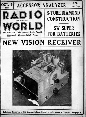
OCT. 11932ACCESSOR ANALYZER15cPer Copy5 -TUBE DIAMONDREG. U.S. PAT. OFFCONSTRUCTIONSW SUPERThe First and Only National Radio WeeklyEleventh Year -549th IssueFOR BATTERIESNEW VISION RECEIVERForeign Feature PhotosTelevision Receivers of this type are being exhibited at radio shows in Europe. See page 3.
RADIO WORLDOctober 1, 1932Parts for the 1933 DIAMONDComplete Kit, less tubes, less cabinet, (Cat. D4CK). . .For A Radio 13.58ManufacturerONE of the outstandingcircuits, the 4 -tube 1933115 West 45th StreetDiamond for a -c operation,105-120 volts, 50-60 cyclesNEW YORKcan be constructed mosteconomically. The circuituses a 58 r.f. amplifier,Must sublet at sacrifice floor or sections suitable for offices and opera-menttions. 100 percent manufacturing ACwith special antenna treatboosting thegainand DC currents. Apply on premisesor telephone PEnnsylvania 6-2300.mightily; a 57 power detector, a '47 output tubeand an '80 rectifier. Younever in your life heardsuch performance on fourtubes!HermanBernard,de -condensers,oneRADIO MEN -Increase Income!signer of the circuit, usedPolymet 8 mfd. wet electrolytic"How To Rake Money In RadioServicing," writtenby Zeh Bouck especially for Radio News,is the answerthe burning question of the hour!Prepared aftermonths of effort and at great expense, it tells the radioservice man how to make his business show a profit.towith two insulating washers and special lug. Thesewashers and lug, at onlywashers and oneAlso, Rola full dynamic(Series F) with 2500 -ohmspecial lug, 49c.49c each.Cat.RO-25,Rolafullwith output transformerpedancebuiltfield coil.Seriesbuilt in,in (blackF.alsoleads)dynamic speaker,matched Imfield coil8" diameter cone.93.83of '472500 -ohmDe Jur Amsco shielded straight frequency line dual condenser, 0.00035 mfd.,brass plates, IA" shaft, 21i" long as complete safeguard against bodycapacity. Cat. DJ -ASCat. EQ-100, 20-100 mmfd. Hammarlund equalizer200 -turn center -tapped r.f. honeycomb choke coil. Cat. DCH @250,000 ohm potentiometer with switch (Cat. P -250 -SW)100-0 travelling light dial, escutcheon, bulb (Cat. CRD).91COILS FOR 1933 DIAMOND.10FOUNDATION UNIT .85439.22.40.55.98.90.1920-100 mmfd. Hammarlund equalizer 5.48DIRECT RADIO CO., 143 West 45th Street, New York City360 -Degree CondenserFULL SCALE PICTURE DIAGRAM OF4 -TUBE DIAMONDThis full scale diagram, together with an accompanying article on wiring, adjusting and operating theFour-Tube Diamond, appeared in Radio World datedSept. 17. Sent for 15c a copy. First and secondinstallments of article on the 4 -Tube Diamond appeared in issues of RADIO WORLD, dated Sept. 8and 10. The three copies sent for 45c. Or send 1.50for a three months' subscription and receive thesethree numbers free.RADIO WORLD, 145 W. 45th St., New York, N. Y.It is practicalRADIO WORLDand "RADIO NEWS"BOTH FORONE YEAR7.00Canadianand Foreign15.51toexperimenters, service men and students,monthly for one year each, at a navies of 1.50. Theregular mall subscription rate for Radio World for oneyear, a new and fascinating eopy each week for 52 weeksle 6.00.Send in 1.00 extra, get "Radio News" aloefor a year -a new Issue sash monthfor twelve insiths.the first and only national radio weekly end tho leadingTotal, 64 Issues for 7.00.RADIO WORLD. 140 West 45th Street. New York. N. Y.EVERYBODY who does any radio workwhatsoever, whether for fun or for payor for both, needs a continuity tester, so hecan discover opens or shorts when testing.A mere continuity tester is all right, butOften it is desiredto determine the resistance value of a-unit, to determine ifit is correct, or tomeasure a low voltage, and then a continuity tester thatalso a direct -read-a DC voltmetercomes in triplyhandy.So here is the combination of all three:20 to 375 mmfd. capacity variation, effected over full 360degrees, affords widespreadout, better diallegibility. Great fortest oscillators andall -wave tuning.Price, 3.00 net.renewing existing subscription.N. Y. CitytheFor a limited thee, Radio News is offering thismoney -making book absolutely FREE with a subscriptioning ohmmeter andWorks on 110-120 volts AC or DC, power,RADIO WORLDhow, and when, and why to do things.-up to the minute -and complete.is50 watts. A serviceable iron, with coppertip, 5 ft. cable and male plug. Send 1.50for 13 weeks' subscription for Radio Worldand get these freel Please state if you are145 West 4Sth St.asTHREE -IN -ONETESTER FREE!for 1933 A -C 4 -Tube DiamondCat. DFU atsuchNot only for the active service man, but also for theamateur and experimenter who desires to turn his knowledge and experience into practical money -making channels this book will prove indispensable.It tells youthat caterNEW YORK, N. Y.Drilled metal plated subpanelTwo -gang 0.00035 mfd. SFL condenser, brass plates, 2%" long shaftTwo special tube shields for 58-57Center -tapped 200 -turn honeycomb coilFive sockets (one for speaker plug)Two Polymet 8 mfd. electrolytics; insulators; lugsOne pair of r -f coils, consisting of impedance antenna coil and interstage transformerimportant in timesYou can obtain the two leading radio timbalesl magazIsesDIRECT RADIO CO.143 WEST 45th STREETmoreDept. R.W., 222 West 39th St., New York, N. Y. 1.39.19.40.47Shielded impedance coil for antenna coupler, and shielded interstage transformer (Cat. DP -33), both coils forF R EE!isfor seven months for only 1.00. This is a saving of 75eover the newsstand cost.Send order to Radio News,TWO -GANG SHIELDED 0.00035 MFD. SFL, 1.39SOLDERING IRONwhatpresent?are our Cat. POLY -8, withoneCat.POLY - 8,8 mfd., wetelectrolytic condenser, invertedmounting,withtwoinsulatingAnd,DIRECT RADIO COMPANY145 WEST 45TH STREETNEW YORK, N. Y.LOOK AT YOUR WRAPPERYou will see by the date thereon whenyour subscription for Radio World exIf the subscription is about to runont, please send us renewal so that youwill not miss any copies. Subscriptionpires.Department, RADIO WORLD, 145 West45th St., N. Y. City.A 0 -4% -volt DC voltmeter, a 0.10,000-ohns,hmmeter and a continuity tester. A rheo-stat is built in for correct zero resistanceadjustment or maximum voltage adjustment.The unit contains a three -cell flashlightbattery. Supplied with two 5 -foot- longwire leads with tip plugs. Case is 4 -inchdiameter baked enamel. Weight, 1 lbSent you with an order for one year'ssubscription for RADIO WORLD (52weeks) at the regular rate of 6. OrderCat. PR -500. Use Coupon below.Radio World, 14 W. 45th Street, New York, N. YEnclosed please find 6 for one year's subscrindon for Radio World (one copy a week, 52 issues)Send Cat. PR -500 as premium.NameAddressCityState
kotmer,EditorJ. E. ANDERSONfitirrassvTechnical EditorJ. MURRAY BARRONHERMAN BPINARDAdvertising ManagerManaging EditorThe First and Only National Radio WeeklyELEVENTH YEARNo. 3. Whole No. 549OCTOBER 1, 1932Vol. XXIIPublished weekly by Hennessy Radio Publications Corporation, 145 West 45th Street, New York, N. Y.Editorial and Executive Offices: 145 West 45th Street, New YorkTeleifkotte: BR-yant 9-0558OFFICERS:If 'smeary,Entered as second-class matter March, 1922, at the Post Office at NewBurkePresident a fi dRolandYork, N. Y., under Act of March 3, 1879. Title registered in U. S.Patent Office. Printed in the United States of America. We do notassume any responsibility for unsolicited manuscripts, photographs,drawings, etc., although we are careful with them.Triranircr M. B. Hennessy,HermanittPresidelti ;Bernard, Sterriawy.Price, 15c per Copy; 6.00 perYear by mail. 1.00 extraper year in foreign countries.Subscribers' change of addressbecomes effective two weeksafter receipt of notice.DISCS IN EUROPEFrench Inventor Offers Spiralwith 30 Lenses, Each AdjustedBy Henri de la FaloisOTABLE advancements in the perfection of radio and television ap-N'.paratus were shown at the radioexpositioninauguratedrecentlyby M.Queuille, Minister of Postes, Telegraphs,and Telephones. On the front cover wereproduce a photograph of a radio chassisshown at the exposition.This is a sixtube receiver comprising three screen gridtubes, and audio amplifier stage, a powertube and a rectifier. It is a tuned radiofrequency receiver with three gangedtuned circuits. It is supposed to be applicable to reception of television signalsas well as to reception of broadcast signals.A Lena Scannerherewith is photograph of a televisiontransmitting scanner as demonstrated atthe exposition. The French are knownfor the fine workmanship of their scientific instruments, and in the constructionof this scanner they have lost none oftheir reputation. It is a fine lookingmechanism.The disc is apparently driven by meansof a synchronous motor, which constitutesthe base of the assembly. The toothedwheel on the main shaft directly in frontof the disc and directly over what appearsto be an audio transformer constitute theelements of a generator of a synchronizingsignal which is sent as a modulation onthe television carrier.The DriveThis drive arrangement can also be usedIn that case the drivingmotor in the base should be of the universal or induction types and the powersupplied to it should be just sufficient todrive the disc at the required speed. Thesynchronizing signal received from thetransmitting station is then impressed onthe phonic wheel attached to the shaftthrough the coil underneath the toothedwheel. The synchronizing signal will thenhold the disc in synchronism with that ofthe transmitter for as the disc tends tofor receiving.speed up, relatively to speed of the transmitter, the synchronizing signal will retard it a little, and conversely, when the(Cori inued on next page)
RADIO WORLD4October 1, 1932GAINIn Direct Coupled CircuitsChoice of Constants to Avoid Frequency DistortionBy Einar AndrewsTHE voltage gain in resistance coupledamplifiers is easily determined if weknow what is the amplification constantof the tube and the load impedance and theinternal resistance of the tube. Suppose theamplification factor is u, the internal resistance r, and the load resistance R. Thetotal resistance in the plate circuit is there-condenser capacity or the grid leak resistance high or to make both of them high.The essential thing is to keep the productof them high. However, if we make thegrid leak resistance low and make the prod-uct large by increasing the stopping condensercapacity,wereduce theampli-for r R. If we impress a voltage of Evolts on the grid, the effective voltage inthe plate circuit resulting from this voltageis uE. The phase is reversed so that weshould use the negative sign, but if we areonly after the magnitude we need not consider it. Then we have a voltage of uEfication on all frequencies. The grid leak,therefore, should be made as large as practical and then the stopping condenser shouldand consequently the plate current will beDrop in Stopping Condensernot the current that would be measured witha d -c instrument in the plate circuit.The idea is that there should be just asand a resistance of r -I -R in the plate circuit,uE/(r R). This is the signal current andThe voltage drop in the load resistance,which is the output voltage, is the product ofthis current by the load resistance. That is,the output voltage is uER/(r-FR). If wedivide this by the input voltage we get thevoltage gain. Hence the voltage amplification of the tube and the coupler isuR/(r-I-R). This is the result in the verysimplest case. In any practical case, however, the load impedance is not a simple re-ristance but rather a complex impedance.First we have a shunt capacity between theplate of the tube and the cathodes. Then wehave, in most cases, a stopping condenserbetween the plate of the tube and the gridof the next. Then we have a grid leakfrom the grid to the cathode, effectively,and finally we have a capacity between thegrid and the cathode.be chosen so that the product of the gridresistance and the stopping capacity is sufficiently high. If the grid leak is made toolarge the grid will block as a result ofgrid current.little voltage drop across the stopping condenser as possible, and as much as possibleacross the grid leak, and this shouldbeat the very low frequencies the stoppingcondenser reduces it.The effect of theshunt capacities and the stopping capacityis to make the transmission characteristicsimilar to that of a broadly tuned circuit. Itis a matter of design to make this characteristic as broad as practical.The amplification of the low frequenciescan be kept up by making either the stoppingThis method does not completely com-pensate for the losses in the shunt capacitiesbecause the damage has been done before thetuned circuit comes into play. It is alsopossible to compensate by means of regeneration at the high audio frequencies, butthis leads to complex circuits.The need for building up the high audiofrequencies is considerable because they arefirst suppressed to a high degree in thetuner and then they are further depressed inthe audio amplifier. For all that, peoplehave become accustomed to reproductionwhich tend to increase the strength of thehigh notes, particularly in connection withthe 247 tube. When these effects are toostrong there is a preponderance of highCompensationdeviation at the two extremes of the fre-capacity should be 7,880 mmfd.grid leak at 20 cycles per second the productof R and C should be 0.056. Suppose, thenIf we were to compute the actual voltageamplification in any typical case we wouldhave to take account of the capacities andquency range. At the high frequencies theshunt capacities reduce the amplification andHence the coil used may be wound withfine wire. Suppose we use a coil of 0.5henry inductance. Then the effective capacity across it should be 788 mmfd. Ifwe use a coil of 0.05 henry inductance thelacking in high notes and when there is acircuit that does well with the high notesbe shown that to get most of the dropacross the resistance the value of RCwshould be as large as possible, where w istwo pi times the frequency. If 99 per cent.of the voltage drop is to occur across theEffect of Capacitiescomplex and for most audio frequencies theresult of the complex formula is practicallythe same as that of the simple. There is aIt should not be too highlyresonant for then there will be a sharp peakat 8,000 cycles rather than a broad hump.judged at the lowest frequency to be amplified without appreciable distortion. It canthat we select a grid leak of half megohm.Then C should be 0.112 microfarad. Forbroadcast reception it is not necessary touse a large value of RC than about 0.05.That is, if the grid leak is 0.5 megohm, itis not necessary to use a larger condenserthan 0.01 mfd. But if it is necessary touse a larger value of RC than about 0.05.stop blocking, the condenser should be in-the grid leaks as well as of the load resistance. The resulting formula is rather8,000 cycles.creased proportionately.It is more difficult to prevent loss at theWhile we can remove all external shunt capacities in mostinstances we cannot remove or reduce theinternal capacities. In the plate circuit ofthe detector a by-pass condenser is usuallyrequired. This must be kept as small aspossible in order to avoid loss of amplification on the high frequencies.In case it is absolutely necessary to keepthe amplification up to about 10,000 cyclesabout the only thing that can be done is tohigh audio frequencies.introduce some form of equalizer. A paralleltuned circuit in series with the load resistance is one way. We might adjust thistuned circuit so that it resonates at aboutlisteners demand tone control, which isnothing but a device for cutting out the highaudio notes. Of course, there are effectsnotes and there is a good reason for de-pressing them. However, there is a greaterneed for building up the low notes.Test for High NotesThe test for the presence of high notesin about the correct degree is good articulation in speech. When some one is talking,is an effort required to understand what hesays, or does understanding come withoutcareful listening and straining of the ears?Particularly, do the hissing sounds comethrough the speaker or through the listener'simagination? Does "the" sound like a "the"or like a grunt?Even in music the actualof thehigh notes is necessary. presenceWe rememberin the early stages of radio broadcastingthat the violin was about the only instrument that came trough well. The organwas a failure, largely due to absence of lownotes and the presence of too much rever-beration. The piano was also a failure,mainly due to absence of both high andlow. Music lovers refused to listen to the"thumping." The low notes give a richness to the music and the high frequenciesgive life and sparkle. Both must be presentin the output of the loudspeaker or the reproduction will not be natural.French Television Scanner(Continued from preceding page)lens forms a complete image of thereceiving disc slows down, relatively to to be transmitted but the images scenemovethe transmitting disc, the synchronizing relatively to the scanning spot. Hencesignal speeds it up. Thus the transmitting as the disc turns around once all theeledisc governs the speed of the receiving disc mental areas of the object are passed inalthough it does not drive it.review before the scanning spot.The disc has 30 lenses set in a spiral,The photo -electric cell is also inside theeach lens being carefully adjusted by three telescopic tube. Hence the light fromscrews to correct alignment. The mask the elemental areas passes directlyintowhere the actual scanning takes place is the cell.located inside the telescopic tube and conIn case this scanner is used for recepsists of a tiny hole in an otherwise opaque tion a crater lamp or some othermodu-sheet in the focal plane of the lenses. Eachlable point source of light is located insidethe telescopic tube. The image of thispoint source, reduced to a small intensespot of light, is thrown on the screen anddistributed by the moving lenses.The disc is made of thicker materialthan is the custom in this country and thisfact tends to make the speed steadier,due to the greater momentof inertia.But it also requires a little moredrivingpower. The greater thickness, of course,simplifies the mounting and adjusting ofthe lenses. Other features are the longshaft and the sturdy bearings.
RADIO WORLDOctober 1, 19325THE AC CESSOR-ANALYZEROperating Receiver May Be Tested,Also a "Cold" One By Resistance MethodBy Edgar ForbesTHE Accessor, described in these columns recently, and concerning whichdata were printed as recently as lastBOTTOM VIEW OF UNIVERSAL SOCKETweek, may be combined with a voltage -current -resistance selector, so that you have aset analyzer, with additional resistance -meas-uring service, and independent use of themeter for external measurements.What an Accessor does is simply to renderaccessible the current and voltages in a receiver. The panel is simplified by use of auniversal socket, so that the same socketreceives tubes of the UX, UY and six -pintypes. For special type tubes, such as UV 199, WD -11, WD -12 and others, adaptersare needed both for the Accessor panel andCLOSED CIRCUITOPENED BY SWITCHI-- jtCOEK Esu Escthe Accessor plug (to fit into the set socket),and the 7 -pin base tubes made by some ofthe smaller tube manufacturers are includedin this category. It is not practical now toutilize a universal 7 -spring socket, in fact,there isn't any such, and no present intentionEP43OPEN CIRCUITCLOSED BY SWITCH0of making any, until such a type tube be-0comes the dominant one on the market, whichit is very far from being.The Seven -Prong PlugOn this subject the following statementfrom Milton Alden is interesting:"Upon the advent of six -prong tubes, instrument manufacturers shifted almost immediately to six prong analyzer plugs."Now that a seven -prong tube has beenannounced, there is the question whetherthere is going to be a seven -prong analyzer4.404AfP8300030000007630 -SMAIL.sNAsa-iccgoplug available.BOTTOM VIEW"We have designed such a plug to haveready at such time as seven -prong socketsbecome the dominant socket, or when a70.1100001:0oorCABLE PLUGS soCKET6 -PIN CABLEDOUBLEseven -prong tube is produced with a controlgrid cap on the top.6KOLE TOPWIN BASEic6-1101E TOPSPIN BASE(Oy)644011 TOP4911 BASEPLUG"In the meantime, there are some verydefinite disadvantages in having a seven prong analyzer plug."It would mean that almost invariablythe analyzer plug would have to be usedwith an adapter. This added length wouldinstances be a disadvantage in closelyshielded sets and others built in limitedtinuity. At corresponding positions a two -point slider closes otherwise open points, en-inabling the meter to be cut in the circuits asspace.picked up for voltage readings.It was deemed advisable to terminate theaccessor at a socket so that the cable wouldnot have to be dangling there all the time.It is of use only in conjunction with receiver tests, and when other measurementsare to be made it certainly is a cumbersome"In addition to this, new sets are appearing in accordance with the rules of theBoard of Fire Underwriters in which thereis a shield having only a 1-32 in. clearancebetween it and the tube base."To meet these conditions analyzer plugsmade in co-operation with the engineers ofthe test equipment companies have been designed so that the analyzer plugs and theassociate adapters in every instance will nothave a greater diameter than the smallesttube base of a given number of prongs."Socket TerminalThe purposes and wiring of the accessorhave been explained (July 30th, September3d and 24th). The switch used is of thenine -position type, four decks, whereby twodecks of closed circuits have one of thefour of the nine circuits opened by an insulated circuit -opener (CO)for currentreadings, the three not opened when onecurrent is read, or four not in use whenvoltage is read, retaining the circuit con -they are opened for current readings orthing to have around, so a cable with six pin plugs at both ends is used. Adapterspermit access to sockets other than of thesix -spring variety. They are as shown onthe diagram.PrecautionsThe meter is to be built into the presentdevice, and therefore the multipliers andshunts are built in also, and the net resultis that one switch is turned for picking upthe desired points in the receiver (see Sep-tember 3d issue), the other switch for usingthe right range and type of measurement.If the high voltage reading is at one extreme, and the instrument switch alwaysturned to that position after use, then anyaccidental connection will be harir.ess, forthe highest resistance is in series. Alwaysagainst putting a current indicatorbetweenbetween voltage points in the receiver asyou value your meter.No attempt is made to define fully whatyou are to do in regard to voltage and current ranges, as it is assumed you have ameter and want to use it. Of course, themeter ought to be fairly sensitive, and it isrecommended that it be a 0-1 ma, if you haveany choice, or a still more sensitive instrument.The device used was a 0.-0.5 ma,consequently the series resistor for 300 voltsmaximum was 600,000 ohms, that for 30volts was 60,000 ohms, that for 3 volts was6,000 ohms. The 6,000 -ohm unit was usedalso in conjunction with 3 battery volts forresistance measurements (100 to more than100,000 ohms) and the 60,000 -ohm spool,with 30 battery volts, for 20,000 to morethan 5,000,000 ohms. Other values shouldhe selected according to the meter you have,a subject discussed in last week's issue, September 24th.The switch SW is simply precautionary,so that if the cable is in a receiver that isturned on, if this switch is open you'll avoidtrouble when trying external testing. Theother switch, on the opposite sideof the pilot lamp, FL, and pointing downward, is also precautionary, as a serious
RADIO WORLD6October 1, 1932derful instrument, that makes positive contact and does not have objectionable "play"at any setting, is 3.5 inches deep, so thecabinet that is to contain the instrumentshould have a 4 -inch depth, which allows forany practical thickness of panel.It is well that the container be metalrather than a wooden box, or if it is a boxthat the meter, except for the top where0000the scale is, be shielded, as it is possible themeter will be used somewhere near a powertransformer. If it is too near a power transformer, even one such as used in a midgetset, there is enough induced voltage in the1/0:00.0meter coil to cause the needle to fly hardagainst the end stop, beyond full-scale posi-4500-0-otion, and yet four or five inches from thetransformer there is no such coupling. Sincethe instrument should be as fully protected419Pri.0sboti SDI/0ORINA0MA23-*6'MAI10NA SVas possible, the metal container or equivalentshield is recommended.051,1/ SWF0short will burn out the pilot lamp, andthe meter won't read if the switch then isclosed when the lamp burns out, for if themeter is attempted to be put in circuit thecircuit will be open and the meter protected. Also if the lamp lights at all do notopen the switch, as a meter protection, unless measuring 100 ma or so, when, a faintlight may be emitted from the latnp, andyet no danger exist.Same Multipliers-in the case of the other switch, the shaftshould be insulated from any and all con-accustomed to work d -c instruments mostly,or a -c instruments separately from d -c in-Another Valuable Deviceproper scale. Each scale is identified, sothere should be no trouble, but habit will getfolk into erroneous readings despite iden-Therefore those who have beencoincide.A handy voltage -current -resistance meter,concerning which constructional data will betifications.The extreme utility of all the purposesprinted in an early issue, uses the WestonUniversal Meter with a five -deck switch,and index per deck. Theoutlined is obvious, except the a -c current,0-1 ma. The a -c meter can not be used forhigher currents because of resultant errors.But the a -c current up to 1 ma sometimesis handy indeed to read, one example beingthe taking of dynamic curves of a detectoror amplifier tube, with 60 -cycle input. Thegrid circuit may have an a -c input from a20 -volt or other secondary of a transformerthat has primary connected to the line. Ifa potentiometer is put across the secondary,switch is the JA -100-578 12 -point, 5 -deckJewell rotary switch.It is not pretended that from the baresketch above that much information can beobtained, as it is concededly rather difficultto interpret a diagram in terms of a switchone can't visualize. However, the uses ofthis device may be related now:D -C Voltages : 5, 50, 500 voltsD -C Currents : 1, 5, 25, 100 ma.A -C Voltages : 5, 50, 500 volts.Output Metera -c voltmeter may be used as an outputmeter provided the same precautions havebeen taken as to segregating the a -c fromthe d -c. The dynamic and static curves ofthe tube therefore may be compared, andmarked numerically or otherwise. A calibration of the resistance values of the unknown in terms of scale divisions or cur-no doubt a better idea of detecting efficiencyobtained from the dynamic curves than fromthe static one.rent, when used with a 7,500 -ohm series resistor and a 7.5 -volt C battery, is necessaryThe method of applying the meter and aswitch to the desired purposes was considered carefully, and the final result is embodied in the diagram. The switch, a won -but this will be given later.The meter itself has a sensitivity of alittle better than 1 milliampere on the dc -t,0osN0O0OOO 0OiCat. N N0 0 OD 0 0 0In the diagram the d -c terminals of themeter are the lower ones, positive at left,negative at right (bottom new), the intendedshunt resistor (permanently connected at thefactory to positive) being between positiveand negative. The switch takes care of establishing the connection of the other sideof the spool to negative when required.Question of AccuracyExtra pains were taken in the design ofThe voltage values of a -c that can beread are of ample range, and therefore theOtorily.turn.The switching arrangement makes for convenience, as all one need to do make any ofthe enumerated measurements is to turn theswitch to the proper position, which may beoofor this instrument must be, and thereforea little ingenuity in the switching arrangement was required. It is believed that thisswitching problem, as well as some otherincidental points, has been solved satisfac-condenser, say 4 mfd. or higher (paper, notelectrolytic) one side to plate, other side tometer, remaining side of meter to plate re-The Built-in ShuntO%source all the time, at least the standard onewhich can be done by connecting a largea -c and d -c.0series with part of the voltage shunt. Aseries shunt has to be across the voltagegrid, a -c input voltages from 20 volts downmay be read, and also the a -c plate current.Of course, the a -c output should be a -conly, that is, the d -c should be removed,The device consists of the meter and rotary switch built onto a panel, underneathwhich are the shunts and multipliers. Thehigh practical value of the instrument isdue to its sensitivity and its dual utility for0source always, so sometimes the meter is inpointer to grid return and one extreme toA -C Current : 1 ma.Resistance : Less than 100 ohms to morethan 500,000 ohms.0As for shunts, these may be series orparallel. Of course the shunt when in use,either type, is in parallel with the meter.But if individual shunts are used they arecalled parallel shunts because across thewhole meter, whereas if the series type isused it consists of virtually a single resistance, tapped, the total across the voltagestruments, should be careful to read thetacts.0ohms, is in circuit for all d -c measurements,so that the multiplier for 50 volts is 45,000ohms and for 500 volts is 495,000 ohms.Since the a -c instrument has an impedanceof 5,000 ohms, the same multipliers may beused for the a -c part of the meter. Thus theadvantage of the built-in shunt for d -c work,to enable economy of series resistors.There are two scales on the meter, onefor a -c
Drilled metal plated subpanel Two -gang 0.00035 mfd. SFL condenser, brass plates, 2%" long shaft Two special tube shields for 58-57 Center -tapped 200 -turn honeycomb coil Five sockets (one for speaker plug) Two Polymet 8 mfd. electrolytics; insulators; lugs One pair of r -f coils, consisting of impedance antenna coil and interstage transformer .