Transcription
Application ReportSNVA733A – May 2015 – Revised June 2015Cost Effective Transformer-less OFFLINE SUPPLY forLight-Load ApplicationsAkshay Mehta, Frank De StasiABSTRACTThis design idea provides a simple non-isolated AC/DC power supply for low power applications. Thedesign uses a "capacitive-dropper" front-end combined with a LM46000 SIMPLE SWITCHER buckregulator from Texas Instruments. The circuit provides 3.3 V at a minimum of 100 mA from a line supply of90 VAC to 265 VAC. Theory of operation as well as design equations and performance results are given.12345ContentsIntroduction .Theory of Operation .Application Circuit and Plots.Conclusion .References .13599List of Figures1Basic Schematic . 22Voltage and Current Waveforms. 33Voltage Ripple at VDC . 64Application Schematic . 65Load Regulation. 76Line Regulation7Max Output Current vs Line Voltage . 88Line Current Vs Line Voltage. 8.7List of Tables11Application Requirements.6IntroductionMany times a simple off-line power supply is required for low power applications such as E-meters, batterychargers, etc. Typically, the need is to convert the line voltage to a small DC value such as 3.3 V or 5 V.This can be done with a line frequency power transformer or a complex AC/DC off-line power supply. Bothapproaches have well known disadvantages of weight, size, and/or complexity. A better option is shown inFigure 1.SNVA733A – May 2015 – Revised June 2015Submit Documentation FeedbackCost-Effective Transformer-less OFFLINE SUPPLY for Light-LoadApplicationsCopyright 2015, Texas Instruments Incorporated1
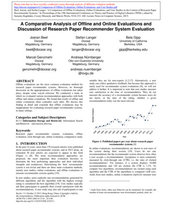
Introductionwww.ti.comBridgeRectifierIDCVDC VINVOUTDC/DCConverterC1IC vLN- vC - vX-ZenerClampsIOUT CBULKFigure 1. Basic SchematicHere we first convert the line voltage to an intermediate unregulated DC rail (VDC) and then use a Wide VINrange DC/DC converter to supply the load. The front-end is the well-known full-wave "capacitive-dropper".The Zener diodes clamp the input voltage to the DC/DC converter under no-load conditions. The inputvoltage to the DC/DC converter (VDC VIN) is set to a relatively high value, so that the current requiredfrom the "capacitive-dropper" can be kept low. For this design we use the LM46000 as the DC/DCconverter and VDC is set to 48 V. The LM46000 converts this down to 3.3 V. For a line voltage range of 90VAC to 265 VAC, this design can supply at least 100 mA to the 3.3 V load. The high step-down ratio,possible with the LM46000, allows the 100 mA load to appear as less than 10 mA load to the front-end.This permits a small value of C1 to be used.It is easy to see that this circuit is connected directly to the line supply and is not isolated. EXTREMECAUTION must be used when experimenting with this design. The user must ensure that the intendedapplication for this power supply, including the load on the LM46000, is completely isolated from anycontact with grounded entities; including people, animals and test equipment. All safety precautions mustbe observed when taking measurements. Test equipment with grounded inputs can not be used with thiscircuit without proper isolation. The user is also responsible for any fusing, transient protection, and/or EMIfiltering required on the input to this circuit.2Cost-Effective Transformer-less OFFLINE SUPPLY for Light-LoadApplicationsCopyright 2015, Texas Instruments IncorporatedSNVA733A – May 2015 – Revised June 2015Submit Documentation Feedback
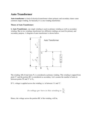
Theory of Operationwww.ti.com2Theory of OperationThe idea behind this circuit is that the series capacitor C1 acts as a lossless resistance and the reactanceof the capacitor will set the maximum current that can be provided. Since a normal electrolytic capacitorcannot handle the stresses resulting from the line voltage, we use "X"-type capacitors which would berated for the maximum line voltage in our range. From Figure 1 we can understand that the current ICthrough the cap C1 would be flowing when there is a voltage differential across the capacitor. Thecapacitor current would steadily increase while vLN is increasing. When the line voltage reaches the peakvoltage, C1 stops charging, because the slope of the differential voltage across it goes to zero. Figure 2shows the relevant waveforms; where we have the following definitions:vLN line voltagevC C1 voltageiC C1 currentvX Voltage at input of bridge rectifierVLN RMS line voltageVDC VIN DC intermediate bus voltage and input voltage to DC/DCVOUT Output voltage of DC/DCIOUT Output current of DC/DC user load currentVD One diode dropF line frequency 1/Tη Efficiency of LM46000vLNvcvxT/2T0T1icFigure 2. Voltage and Current WaveformsSNVA733A – May 2015 – Revised June 2015Submit Documentation FeedbackCost-Effective Transformer-less OFFLINE SUPPLY for Light-LoadApplicationsCopyright 2015, Texas Instruments Incorporated3
Theory of Operationwww.ti.comThe peak capacitor current can be obtained as follows:IP2S F C1 VLN 2where IP Peak C1 current(1)To know the amount of DC current (IDC) coming from the bridge rectifier, we would first need to know thetime duration, T1, for which the capacitor current is zero. Observing the timing in Figure 2 we can see thatat time T1 one of the diode pair turns on. Thus the voltage across the capacitor at time T1 would be equalto the peak line voltage minus VDC . From that time T1 can be equated to be as follows:T1§2 VIN VD1 cos 1 1 VLN2S F · ¹(2)Knowing time T1, we can find the DC current value. The IDC is basically the area under the rectifiedcapacitor current curve (iC). The area can be found by integrating the curve from time T1 to T/2 andmultiplying by 2. The expression for IDC is shown as follows:IDC§V VD4 VLN 2 F C1 1 IN 2 VLN · ¹(3)This is the DC current that the capacitor C1 can provide to the input of the LM46000. As mentionedpreviously, the advantage of interfacing a Wide VIN DC/DC converter with the "capacitor drop" front-end isthat a fairly small duty cycle can be possible. This means that the input current requirement will also befairly small for a required load current. The DC input current to the LM46000, IINDC, can be estimated byassuming the worst case efficiency of the switching converter shown as follows:VOUT IOUTIINDCVIN K(4)The worst case situation in the cap drop circuit will occur at lowest line voltages. The capacitor C1 needsto be sized such that at lowest line voltage of 90 VAC it can still provide enough current to keep the bulkcaps charged to 48 V. At lowest line, the Zener diodes will not see any current flowing through them andthe IDC will be equal to IINDC. Knowing this value, we can then calculate the amount of capacitance we needat minimum VLN of 90 VAC as shown:IDCC1§V VD · 4 VLN 2 F 1 IN 2 VLN ¹ (5)4Cost-Effective Transformer-less OFFLINE SUPPLY for Light-LoadApplicationsCopyright 2015, Texas Instruments IncorporatedSNVA733A – May 2015 – Revised June 2015Submit Documentation Feedback
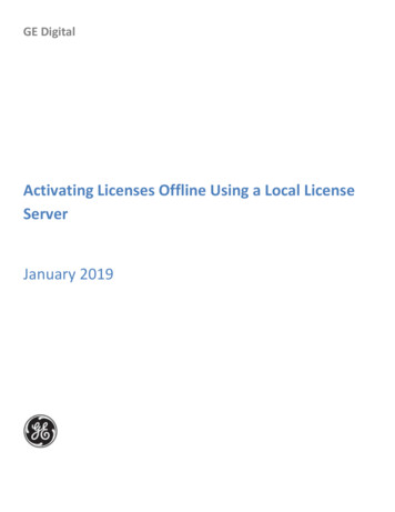
Application Circuit and Plotswww.ti.com3Application Circuit and PlotsWARNINGCAUTION MUST BE USED IN THE CONSTRUCTION, TESTING, ANDUSE OF THE CIRCUITS FOUND IN THIS DOCUMENT.LETHAL VOLTAGES ARE PRESENT IN THESE CIRCUITS THATMAY CAUSE INJURY.THE USER MUST ENSURE THAT SAFETY PROCEDURES AREFOLLOWED WHEN WORKING ON THESE CIRCUITS.Let's look over some BOM calculations for the capacitor dropping circuit.3.1Dropping CapacitorThe dropping capacitor C1 is sized for the lowest line voltage thus ensuring that the load current ismaintained even at the worst case. For our design requirements and from Equation 5 the cap C1 is sizedto be about 0.56 µF rated for 375 VAC. Care must be taken to not oversize this capacitor. Oversizing thiscapacitor would increase IDC and would cause greater power dissipation in the Zener diodes at higher linevoltages. This capacitor must be rated for the highest peak line voltage.3.2Zener DiodesThe LM46000 is rated for a maximum input voltage of 60 V and a load current of 500 mA. Therefore VDCcan be clamped at a high voltage of 48 V. The Zener voltage established VDC. As shown in the schematictwo Zener diodes of 24 V each have been used in series to obtain a clamping voltage of 48 V. It isimportant to size the Zener diodes for the right power requirement. From schematic in Figure 1, we canobserve thatIZIDC IINDC(6)At low line voltages of 90 VAC, to maintain load at the output of the converter all of IDC would be suppliedto the input of the converter. The Zener current IZ would be zero then. But with increasing line voltages, IDCwould be more than what the switcher requires and therefore IZ would no longer be zero. At high linevoltage IZ would be considerably high and would therefore cause some heating in the device. The worstcase is when all of IDC flows in the Zener. The power in the Zener is then:PZ3.3IDC VDC(7)Bulk CapacitorA bulk electrolytic capacitor of 680 µF is used to hold the 48 V with low ripple voltage. Keeping the ripplevoltage on the intermediate rail low will also help with keeping the output voltage ripple low. Havingenough bulk capacitance is also important to maintain enough voltage at the input of converter in case ofa fast load transient at the output of the converter. A range of 470 µF to 680 µF was tested to beappropriate. Figure 3 shows the voltage ripple at the input of the LM46000. The 680 µF cap results in a100 mV ripple at 120Hz. Since the ripple at VDC is at a relatively low frequency, it is important to keep theripple low because it cannot be filtered effectively by the inductor and the output capacitor of theLM46000.SNVA733A – May 2015 – Revised June 2015Submit Documentation FeedbackCost-Effective Transformer-less OFFLINE SUPPLY for Light-LoadApplicationsCopyright 2015, Texas Instruments Incorporated5
Application Circuit and Plotswww.ti.comRipple on VDC, 100mV/div5ms/divFigure 3. Voltage Ripple at VDCThe newly released LM46000 Wide VIN DC/DC converter was interfaced with the "capacitive drop" frontend to obtain the schematic as shown in Figure 4.BridgeRectifier120µHL2x 4.7µFVIN 48VVINCIN1.3M C1A.C. Line Input90Vrms to 265VrmsFusing,Transient protection,EMI filtering, etc.0.56µF310 VACRENT100k RENBPGOODCBOOTCBOOTSS/TRKSYNC 680µF63VAGNDCOUT 2x 47µF0.47µFBIASCBIAS1µFCFFRFBT1M FB68pFRT24V1WCBULKLM46000ENABLE24V1WVOUT 3.3VSWVCCPGNDCVCC2.2µFRFBB432k RT200k Figure 4. Application SchematicTable 1. Application Requirements6ParameterValueVLN90 VAC to 265 VACVOUT3.3 VIOUT100 mAη at 120 VAC and 160 mA71 %IRMS from line at 120 VAC23 mACost-Effective Transformer-less OFFLINE SUPPLY for Light-LoadApplicationsCopyright 2015, Texas Instruments IncorporatedSNVA733A – May 2015 – Revised June 2015Submit Documentation Feedback
Application Circuit and Plotswww.ti.comThe BOM for the LM46000 can be calculated for VIN of 48 V to VOUT of 3.3 V. The design can be obtainedfrom the datasheet for LM46000. The data sheet has detailed calculations for the entire BOM. The risingUVLO threshold on the LM46000 was set to about 30 V. This helps with limiting the inrush currents andpotential voltage crash at the input of the converter. The resulting falling UVLO threshold is about 25 V.For the application circuit shown in Figure 4 load regulation test was performed at 120 VAC line voltageand line regulation test was performed at 100 mA ILOAD. At light loads, the LM46000 enters the PFM mode.In this mode the switching frequency is folded back to improve the efficiency. In PFM operation, a smallpositive DC offset is required at the output voltage to activate the PFM detector. This can be seen inFigure 5. Please refer to the LM46000 data sheet (SNVSA45) for more information.3.393.3853.38Output Voltage 060.080.10.120.140.160.18Output Current (A)Figure 5. Load Regulation3.363.3593.358Output Voltage 25150175200225250275300Mains Voltage (VRMS)Figure 6. Line RegulationSNVA733A – May 2015 – Revised June 2015Submit Documentation FeedbackCost-Effective Transformer-less OFFLINE SUPPLY for Light-LoadApplicationsCopyright 2015, Texas Instruments Incorporated7
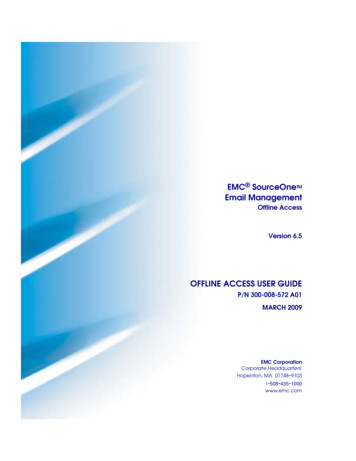
Application Circuit and Plotswww.ti.com0.6Maximum Output Current Mains Voltage (VRMS)Figure 7. Max Output Current vs Line Voltage0.06Mains Line Current (ARMS)0.050.040.030.020.010050100150200250300Mains Voltage (VRMS)Figure 8. Line Current Vs Line VoltageWith increasing line voltage, more current can be delivered to the input of the LM46000. This means thatmore current can be delivered at the output also. At the max line voltage of 265 VAC about 500 mA ofcurrent can be delivered to the output of the LM46000. Figure 7 shows the max current capability atincreasing line voltages.8Cost-Effective Transformer-less OFFLINE SUPPLY for Light-LoadApplicationsCopyright 2015, Texas Instruments IncorporatedSNVA733A – May 2015 – Revised June 2015Submit Documentation Feedback
Conclusionwww.ti.com4ConclusionThe cap drop circuit is an easy cost effective approach for low load AC-to-DC conversion. Interfacing witha Wide VIN DC/DC converter can be further useful to draw relatively higher loads at the output whilekeeping the current drawn from the line low. A maximum of 500 mA can be obtained from the output ofthe LM46000 at 265 VAC line voltage. While this circuit is easy to make, utmost care should be taken tocreate a bench prototype and appropriate filtering and protection circuit should be added.5References1. A Capacitor-Fed, Voltage-Step-Down, Single-phase, Non-Isolated Rectifier Authors: Nathan O. Sokal,K. Kit Sum, David C. HamillSNVA733A – May 2015 – Revised June 2015Submit Documentation FeedbackCost-Effective Transformer-less OFFLINE SUPPLY for Light-LoadApplicationsCopyright 2015, Texas Instruments Incorporated9
Revision Historywww.ti.comRevision HistoryChanges from Original (May 2015) to A Revision . Page Changed to VLN from VLINE . 6NOTE: Page numbers for previous revisions may differ from page numbers in the current version.10Revision HistorySNVA733A – May 2015 – Revised June 2015Submit Documentation FeedbackCopyright 2015, Texas Instruments Incorporated
IMPORTANT NOTICETexas Instruments Incorporated and its subsidiaries (TI) reserve the right to make corrections, enhancements, improvements and otherchanges to its semiconductor products and services per JESD46, latest issue, and to discontinue any product or service per JESD48, latestissue. Buyers should obtain the latest relevant information before placing orders and should verify that such information is current andcomplete. All semiconductor products (also referred to herein as “components”) are sold subject to TI’s terms and conditions of salesupplied at the time of order acknowledgment.TI warrants performance of its components to the specifications applicable at the time of sale, in accordance with the warranty in TI’s termsand conditions of sale of semiconductor products. Testing and other quality control techniques are used to the extent TI deems necessaryto support this warranty. Except where mandated by applicable law, testing of all parameters of each component is not necessarilyperformed.TI assumes no liability for applications assistance or the design of Buyers’ products. Buyers are responsible for their products andapplications using TI components. To minimize the risks associated with Buyers’ products and applications, Buyers should provideadequate design and operating safeguards.TI does not warrant or represent that any license, either express or implied, is granted under any patent right, copyright, mask work right, orother intellectual property right relating to any combination, machine, or process in which TI components or services are used. Informationpublished by TI regarding third-party products or services does not constitute a license to use such products or services or a warranty orendorsement thereof. Use of such information may require a license from a third party under the patents or other intellectual property of thethird party, or a license from TI under the patents or other intellectual property of TI.Reproduction of significant portions of TI information in TI data books or data sheets is permissible only if reproduction is without alterationand is accompanied by all associated warranties, conditions, limitations, and notices. TI is not responsible or liable for such altereddocumentation. Information of third parties may be subject to additional restrictions.Resale of TI components or services with statements different from or beyond the parameters stated by TI for that component or servicevoids all express and any implied warranties for the associated TI component or service and is an unfair and deceptive business practice.TI is not responsible or liable for any such statements.Buyer acknowledges and agrees that it is solely responsible for compliance with all legal, regulatory and safety-related requirementsconcerning its products, and any use of TI components in its applications, notwithstanding any applications-related information or supportthat may be provided by TI. Buyer represents and agrees that it has all the necessary expertise to create and implement safeguards whichanticipate dangerous consequences of failures, monitor failures and their consequences, lessen the likelihood of failures that might causeharm and take appropriate remedial actions. Buyer will fully indemnify TI and its representatives against any damages arising out of the useof any TI components in safety-critical applications.In some cases, TI components may be promoted specifically to facilitate safety-related applications. With such components, TI’s goal is tohelp enable customers to design and create their own end-product solutions that meet applicable functional safety standards andrequirements. Nonetheless, such components are subject to these terms.No TI components are authorized for use in FDA Class III (or similar life-critical medical equipment) unless authorized officers of the partieshave executed a special agreement specifically governing such use.Only those TI components which TI has specifically designated as military grade or “enhanced plastic” are designed and intended for use inmilitary/aerospace applications or environments. Buyer acknowledges and agrees that any military or aerospace use of TI componentswhich have not been so designated is solely at the Buyer's risk, and that Buyer is solely responsible for compliance with all legal andregulatory requirements in connection with such use.TI has specifically designated certain components as meeting ISO/TS16949 requirements, mainly for automotive use. In any case of use ofnon-designated products, TI will not be responsible for any failure to meet dioAutomotive and fier.ti.comCommunications and Telecomwww.ti.com/communicationsData Convertersdataconverter.ti.comComputers and Peripheralswww.ti.com/computersDLP Productswww.dlp.comConsumer ergy and Lightingwww.ti.com/energyClocks and wer Mgmtpower.ti.comSpace, Avionics and ollersmicrocontroller.ti.comVideo and Imagingwww.ti.com/videoRFIDwww.ti-rfid.comOMAP Applications Processorswww.ti.com/omapTI E2E Communitye2e.ti.comWireless Connectivitywww.ti.com/wirelessconnectivityMailing Address: Texas Instruments, Post Office Box 655303, Dallas, Texas 75265Copyright 2015, Texas Instruments Incorporated
Let's look over some BOM calculations for the capacitor dropping circuit. 3.1 Dropping Capacitor The dropping capacitor C1 is sized for the lowest line voltage thus ensuring that the load current is maintained even at the worst case. For our design requirements and from Equation 5 the cap C1 is sized to be about 0.56 µF rated for 375 VAC.