Transcription
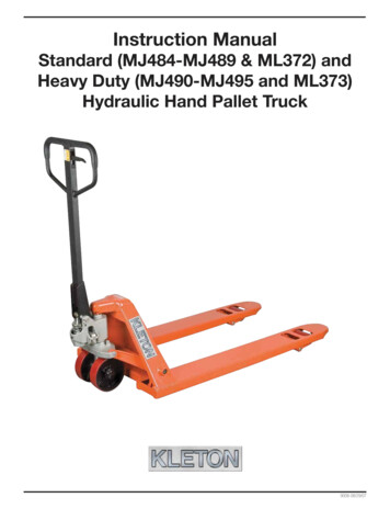
Instruction ManualStandard (MJ484-MJ489 & ML372) andHeavy Duty (MJ490-MJ495 and ML373)Hydraulic Hand Pallet Truck9008-08/29/07
WARNING! Read and understand the entire operator’s manual before using the pallet truck. Don’t load pallet truck beyond rated capacity of 5,500 lbs. for thestandard models and 6,600 lbs. for heavy-duty models. Secure load before transporting. Keep the load centered on the pallet. Don’t operate loaded pallet truck on ramps or inclines. Always wear appropriate safety shoes. Never leave a loaded pallet truck unattended in the raised position;always lower load to the floor.PALLET TRUCK ASSEMBLYNote: Individual trucks are assembled and ready to use. Pallet trucks purchased incrate quantities (6 units to a crate) require some assembly.Tools needed for assembly: hammer, flat screwdriver, 14mm wrenchTo attach handle assembly to the frame:1.2.*** IMPORTANT - SAFETY ***Verify that spring safety pin is in place.The pin should be well rested in theholes situated on each side of the pumphousing. If the safety pin is not restedproperly in one of the holes, put pressure on the spring using a “C" clamppushing down on the pump stem. Oncepressure is relieved on the pin, reinsertproperly and remove clamp slowly,Insert handle pin into corresponding holes and using ahammer, drive in one spring pinon one side only.3.4.Insert handle pin without thehandle and verify that the centerhole is facing you.If handle pin’s center hole isfacing away from you, insert pinfrom other side.*** IMPORTANT - FACT ***The up/down lever’s chainpasses through this center hole.If left this way, the chain willhave an “S" form and be undertoo much tension, making theup/down lever difficult to useaccurately.
5.*** IMPORTANT - CHAIN****Before this step, make sure tofeed the chain on the outsideof the piston stem roller (seeyellow arrow). If left in its properposition, it will not be possible toinsert the handle pin and chain,breakage may occur.Align handle holes with pumphousing holes and push throughhandle pin (see red arrow)6.Make sure that handle pin iscompletely through the handleand resting on the other side.7.8.9.10.Pull down on the handle torelease the tension on the safetypin. CAREFULLY remove thesafety pin.Once the chain is in the properposition, check to see that itmoves freely and that it is notobstructed.11.Pump the lever a few times toraise the forks. Put the up/downlever to its NEUTRAL position.Using a 14mm wrench and aflat screwdriver, adjust the valvecam so that the forks don’t loweror rise (if handle is pumped) atthis position.Feed the chain and nut first backinside the handle THROUGH thehandle pin’s center hole.***IMPORTANT - TIP ***Release the up/down lever toits lowest position to make theprocess easier.Using both hands,push on the valvecam to raise thehook inside thehousing and feedthe end of thechain in the cam.(see image atright)12.*** IMPORTANT - FINAL CHECK ***Test all the features of the pallettruck before this step. The handleshould be pumped with full strokesto prime and eliminate air in thesystem. The up/down lever should bechecked at the handle’s lowest position for this puts the most tensionon the chain. Once the pallet truck isadjusted properly and is performingwell, drive in the second spring pinusing a hammer.
OPERATING PALLET TRUCKTo raise the forks, place handle lever in UP position (bottom part of the handle slot).See Figure 2.DOWNNEUTRALUPFigure 2To lower forks, pull lever to DOWN position (upper part of the slot).To freely move the handle, set the lever in NEUTRAL (center notch of the slot).To lift a load:1.2.3.4.Lower forks to lowest position.Insert forks under load or into pallet.Place lever in UP position (bottom part of the slot).Move handles up and down until forks reach desired height.To move a load:1. Place lever in NEUTRAL position (center notch of the slot).2. Pull or push to desired location.To lower a load:1. Pull lever to the DOWN position (upper part of the slot).2. Pull forks away from load.
TECHNICAL PARAMETERStandardModel No.MJ484MJ485MJ486MJ487CapacityH - MaximumRaisedHeightS - LoweredHeightL - ForkLengthDiameter ofthesteer wheelDiameter oftheload wheelMJ488MJ489ML372MJ490MJ491MJ492MJ4935500 lbs.6600 lbs.2500 kg3000 kg7 1/2"7 1/2"190 mm190 mm3"3"75 0mm915mm1070mm1220mm915mm1070mm1220mm1220mmE - ForkWidthB - ForkOutsideDistanceHeavy -Duty6 1/4"6 1/4"160 mm160 mm20 1/2"27"20 1/2"27"520 mm685 mm520 mm685 mm7" x 2"7" x 2"180 mm x 50 mm180 mm x 50 mm3" x 3 5/8"3" x 2 3/4"74 mm x 93 mm74 mm x 70 mm
TROUBLESHOOTINGPossible problems could arise in the operation of your hydraulic pallet truck. Their probable cause(s) andcorrective action(s) follow:ConditionHydraulic unit doesnot liftOnce lifted trucklowers by itselfFork does not lowerProbable CausesCorrective ActionOil low in tankMake sure there is no till leakage from valve and add oil.Relief valve not seated properly or air in thesystemSee “Cleaning Relief Valve" in this manual.Defective pressure seal in main cylinderConsult authorized service centre.Relief valve not adjusted properlyAdjust valve by pressure adjustment screwRelief valve not seated properlySee “Cleaning Relief Valve" in this manual.Defective pressure seal in main cylinderConsult authorized service centreRelief valve not adjusted properlyAdjust valve by pressure adjustment screwOil leakageConsult authorized service centreCam chain brokenReplace cam chain.UP-DOWN cam nut out of adjustmentRefer to “Adjusting UP-DOWN Cam" in this manual.Broken fork rods and linkageConsult authorized service centreCam chain lock-nut fallen offReplace cam chain lock-nutLever does not set atRelief valve not adjusted properlyNEUTRAL positionAdjust valve by pressure adjustment screwCleaning Relief ValveOver time, relief valve may become clogged with debris and will not work properly.To clean relief valve, flush the hydraulic system as follows:Hold the UP/DOWN lever to the DOWN position and move the handles up and down several times.Adjusting UP-DOWN CamDO NOT adjust the up/downlever control using the locknut at the end of the handlechain. If nylon locking threadsare removed from the screwthreads, rolling vibration willcause the nut to unscrew andfall off, leaving the up/downlever unusable.Use proper set screwand lock nut adjustmentlocated on the side of thepump. This feature wasdesigned to ease the pallettruck adjustment.Tools required are:flat screwdriver and a14mm wrench.
HYDRAULIC HAND PALLET TRUCK ASSEMBLY89A
Parts list for Standard and Heavy-Duty ModelsNo.Order No.DescriptionQtyNo.Order No.Description1MJ552Handle149MJ600Main Lift Piston12MJ553Spring Pin 4x30251MJ613Lock-Nut23MJ554Blocking Spring152MJ614Guide Roller24MJ555Spring Pin 4x20153MJ615Bolt25MJ556Roller154MJ61619" Shaft for 20.5" W pallet trucks16MJ557Spring Pin 6x30154MK70424" Shaft for 27" W pallet trucks17MJ558Spring Pin 4x20155MJ617Retaining Ring28MJ559Control Lever156MJ618Lifting Yoke, 20.5" W, Orange Std19MJ560Control Rod156MJ619Lifting Yoke, 27" W, Orange Std110MJ561Chain156MJ620Lifting Yoke, 20.5" W, Blue HD111MJ562Chain Lock-Nut156MJ621Lifting Yoke, 27" W, Blue HD112MJ563Roller157MJ622Bushing213MJ564Roller Pin158MJ623Retaining ring214MJ565Handle Pin159MJ624Thrust Plate Pin215MJ566Oil Plug160MJ625Bushing216MJ567Oil Plug O-ring161MJ585Spring Pin 5x30217MJ568Relief Screw162MJ627Clevis218MJ569Spring163MJ628Rod, 36" Length, Std219MJ570Relief Valve163MJ629Rod, 42" Length, Std220MJ571Steel Ball163MJ630Rod, 48" Length, Std221MJ572Spring Pin 5 x 35163ML048Rod, 36" Length, HD222MJ573Rear Pump Piston163ML049Rod, 42" Length, HD223MJ574Spring Cap163ML050Rod, 48" Length, HD224MJ575Spring164MN300Tandem Wheel Shaft225MJ576Dust Seal165MJ585Spring Pin 5x30426MJ577U-Ring166MJ633Washer427MJ578Control Stem O-Ring267MJ634Arm Pin228MJ579Control Stem with Spring168MJ635Load Wheel Shaft229MK798Brass Nut O-Ring169MJ636PU Load Wheel for Orange Models230MJ581Brass Nut169ML368Nylon Load Wheel for Orange Models231MJ582Spring Pin 8x50170MK984Ball Bearing432MJ583Spring Pin 8x45171MJ585Spring Pin 5x30233MJ584Thrust Bearing172MJ639Wheel Lever Bracket234MJ585Spring Pin 5x30273MJ640Washer135MJ586Thrust Plate174MJ641Oil Plug136MJ587Retaining Ring175MJ642Exit Roller137MJ588Wheel Shaft176MJ643Spring Pin 5x50138MN256PU Steer Wheel276BMN447Bolt 6x12 mm138ML367Nylon Steer Wheel277MN602Cylinder Housing139MK984Ball Bearing480MK983Washer840MJ591Retaining Ring281MK984Ball Bearing841MJ592Dust Cap282MK985PU Load Wheels for Blue Models442*MJ593Control Valve Assembly182ML369Nylon Load Wheels for Blue Models443FT0005-043Lever183MK986Tandem Plate244MJ595Control Ajustment Set Screw184MK987Spring Pin 5 x 40845MJ596Nut186ML037Pump Cylinder Assembly146MJ597U-Ring187ML042Grease Nipple Valve147MJ5980-Ring188ML047Load Wheel Assembly for Blue Models (PU)148MJ599Dust Seal189MP608Load Wheel Shaft1AMK801Cylinder Housing Assembly1*Includes parts: 27/28/29/30/42Qty
Hydraulic Hand Pallet Truck 9008-08/29/07. WARNING! Read and understand the entire operator's manual before using the pallet truck. Don't load pallet truck beyond rated capacity of 5,500 lbs. for the standard models and 6,600 lbs. for heavy-duty models.
