Transcription
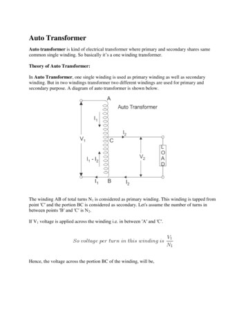
Expedite TransformerCalculations for FlybacksBy Kirby Creel, Senior Design Engineer, Datatronics,Romoland, Calif.When charging defibrillator capacitors, a novelapproach can be used with confidence to comeup with a more exacting design, eliminating the cumbersome aspects of many otherapproaches.Using a flyback topology to generate a highvoltage is a common approach. The voltagecan charge a capacitor for a high-energypulse. Such an approach is used in defibrillator capacitors, photoflash capacitors, strobecapacitors and ignition circuits to name a few. Using a newstep-by-step procedure, it’s possible to quickly realize an initial flyback transformer design for charging a capacitor ina stated amount of time.Following this procedure eliminates “cut and try” andover-design approaches. It also allows designers to selectcritical values with confidence, and can be used to provideinsight as to the effects of holding an element constantand varying other elements. The variables included arefrequency, voltage, pulse width, peak current, load capacitance and efficiency.Before we delve into this novel approach, we need tounderstand the pros and cons of flyback topologies. AdT1D1 C1Vdcvantages include circuit simplicity, a high-voltage outputthat’s not dependent on a large transformer turns ratio, aself-limiting circuit that can be short circuited without anydamage, and an output that can be regulated over a largerange. A flyback also can provide voltage isolation, allowsfor multiple isolated outputs where one output can be usedfor a low-ratio feedback voltage, and does not require asmoothing choke.The disadvantages of flyback topologies include the needfor a large and often bulky transformer, a fast-switchingoutput that can generate problematic EMI signals, leakageinductance that must be kept low for good efficiency and acircuit that can be damaged once a load is removed withoutusing a feedback loop.Fig. 1 shows a simplified circuit and Fig. 2 shows idealized waveforms for a frequency of 50 kHz and a pulse ontime (TON) of 45%.The flyback operates by storing energy on the “charge”portion of the cycle and delivers the stored energy to theload on the discharge cycle. In the case of a flyback, thetransformer is often described as a coupled inductor. DueR10RIMARY CURRENTRAMPS CHARGER2 Q1 MS MSU1Pulsecontrol3ECONDARY CURRENT DISCHARGE EAD TIME Fig. 1. A flyback loop for pulse control keeps a flyback transformerfrom being damaged once a load is removed.26Power Electronics Technology January 2008Fig. 2. Dead time for a flyback transformer increases as thestorage capacitor approaches a full charge.www.powerelectronics.com
voltage, ( t) is the time duration from start to finish ofthe applied pulse and ( i) is the change in current overthe same interval. If i starts at zero, i is equal to the peakcurrent (IPEAK):V ( t )I PEAK A. (Eq. 2)LEq. 2 is Eq. 1 solved for IPEAK. For example, if VA 12 V, t is 0 μs to 15 μs, L 60 μH and IPEAK 3 A.The energy stored in the inductance is:L(I PEAK ) 2U , (Eq. 3)2where U is energy measured in Joules, L is in henriesand IPEAK is in amperes. In the previous example, the energystored in each pulse is 270 μJ.It is during the discharge of this stored energy that thegreatest advantage of the flyback is realized. The outputvoltage will rise to whatever level is needed to cause currentto flow, thus dissipating the stored energy. The voltage ofthe output has limits to be sure, but within the insulationstructure, transistor breakdown, and circuit design, andtaking losses into account, the voltage can rise to veryhigh levels.Though ancient technology now, the most commonexample was the flyback transformer in color TVs with acathode ray tube. These transformers could generate voltages greater than 35,000 V, voltages so high that, when theParameterDescriptionCapacitor100 μFCharge voltage2000 VdcCharge time10 secCircuitDiscontinuous-mode flybackFrequency50 kHzMaximum duty cycle45%Maximum on time9 μs ( t)Input voltage12 VdcEfficiencySee the fourth step and Fig. 3Primary inductanceTo be decidedPeak currentTo be decidedTable. Values for a typical charging circuit.to the diode polarity, current only flows in the secondaryside during discharge. During the charge cycle, energy isstored in the primary inductance by a current ramp. Thedead time shown in Fig. 2 ensures that the flyback is discontinuous. As the capacitor approaches full charge, thedead time increases.The primary current ramp (charge) follows the inductance formula:V ( t)L A, (Eq. 1) iwhere L is the inductance in henries, VA is the appliedMIAwww.powerelectronics.com27L I TA R YPPROVEDPower Electronics Technology January 2008
flyback transformerforms. In a defibrillator, pulse control will be a voltage feedback loop that fixes the number of Joules to be delivered tothe patient. During successive resuscitation attempts, thelevel will increase. For photoflashes, the charge level is fixed.The capacitor will be charged and additional pulses will onlybe applied as a refresh.In photoflash applications, the dead time may be limitedto speed up the charge time. The low dead time and variable discharge produces the characteristic of an increasinghigh-pitch sound. Variations in the pulse-control elementare almost endless. -AXIMUM EFFICIENCY %FFICIENCY %NERGY STORED *OULES Fig. 3. Energy storage efficiency in a flyback circuit is fairly linear up toabout 100 J, before it decreases asymptotically.circuits malfunctioned, the TV could generate damagingX-rays. The analysis is somewhat simplified because theTV flyback transformer performs more functions than justgenerating high voltage. The design of the flyback circuitand transformer for power transformation is well illustratedin Abraham I. Pressman’s book Switching Power SupplyDesign.[1]The block in Fig. 1 labeled “pulse control” can take manyDesign ExampleWith the background provided, we can now tackle theproblem of charging a capacitor to a given voltage in astated amount of time. Designs begin with a list of knownvalues.Let’s illustrate the process by considering the followingexample of a typical design problem, for which the valuesare listed in the table. The application is for charging a defibrillator capacitor. (Caution: The charged capacitor usedin this example can provide a lethal shock.)The first step is to determine the number of Joules required to charge the capacitor:C(VCAP ) 2 100 10 6 (2000) 2U 200 J, (Eq. 4)2228Power Electronics Technology January 2008www.powerelectronics.com
flyback transformer)0%! ! 6DC4 M&, M(figure calculated in the previous equation can be solved withan almost infinite number of solutions. The remainder of thedesign requirements and the 500-µJ calculation limits theanswer to one solution (as shown next).Eq. 1 is an inductance formula, while Eq. 3 is solved forthe inductance. The right-hand side of both equations areequal to each other. The resulting expression, with onlyone unknown, can be solved for the peak current. Havingfound the peak current, the value is entered into the original equation and solved for the inductance. For a “sanitycheck,” both formulas are solved for the inductance. Theequal results provide confidence that the calculations wereperformed correctly.2 # 6DC2 1 5 0ULSECONTROLE t i(note that i IPEAK )L Fig. 4. This completed design for a flyback transformer circuit withcomponent values is based on the calculations in this article.L L 2UIPEAK 2L where U is energy in Joules, VCAP is the capacitor voltageand C is the capacitance in Farads.The next step is to calculate the number of chargingpulses (N) in the stated time:N 10 s 50,000 pulses/s 500, 000. (Eq. 5)In the third step, calculate the energy required per charging pulse (UP):Joules200UP 400 µJ/pulse. (Eq. 6)N500, 000The fourth step is to make an estimate of the circuitefficiency and include the factor in calculating the energythat must be supplied. All calculations up to this point arebased on the assumption that there were no losses in theswitching transistor, diode and transformer (winding orcore). Switching transistor, diode, and transformer lossesare shown to a first order. Second-order losses are those forwinding capacitance and leakage inductance.Fig. 3 provides an estimation of a typical loss factor expressed as an efficiency figure. The losses must be includedin the power supplied from the dc source, as shown in thenext calculation. Note that Fig. 3 is an estimate and resultswill vary. Use the result from Eq. 4 (in this case, 200 J) tofind the efficiency value. A number of variables in circuitdesign, layout, transformer design, components and otherswill affect the result. (For very high-voltage designs, evenleakage current paths across the surface of the pc board andleakage within the capacitor must be considered.)2(500 10 6 ).IPEAK 212(9 10 6 ) 2(500 10 6 ) 2I PEAKI PEAK1.08 10 4 1 10 3 2I PEAKI PEAK2I PEAK1 10 3 I PEAK 1.08 10 4I PEAK 9.259 A.Calculate the inductance by substituting the value of IPEAKin both Eq. 1 and Eq. 3 as a check:2(500 10 6 )12(9 10 6 )L (9.259) 29.259L 11.66 µH.L 11.66 µH.Fig. 4 is the completed design with the calculated valuesincluded.A similar application to charging a defibrillator capacitor is charging a photoflash capacitor. Linear Technology’sLT3468 IC performs most functions in a small footprint.The IC is designed around the specific application with someother applications mentioned in the data sheet. One limitation of this device is the breakdown voltage of the switchingtransistor, which at 70 V at 25 C makes it better suited forlower-voltage applications.The LT3468 data sheet[2] provides design information,circuits and typical waveforms, and gives a designer goodinsight into the process, possibly sparking new avenues ofapplication. (Note: The data sheet provides a warning relatedto working with high voltage. Many of the circuits discussedcan provide lethal shocks when working properly.)For further illustration of the design process, the following low-power example was built and tested. Test data, noteson circuit operation and waveform are shown. The designL UP Joules from dc sourceEfficiency400 µJUP 500 µJ/pulse.0.8In the fifth and final step, solve for the unknowns. Thereare two unknowns and two equations previously presentedthat will provide the answer. The unknowns are the transformer primary inductance and the peak current. The 500-µJwww.powerelectronics.com12(9 10 6 ).IPEAKLIPEAK 2.2Solve for L:U 29Power Electronics Technology January 2008
flyback transformer12 V12 V T1 (see text)100 MFA6 MF7681 k70.010MFU124 751 k77.5 k7Counter(note 3)INPUT100 k73.6 k7 12 V12 V 12 V8 14QNoconnectionQ51U246210 7 11 3DOutputmonitor(see note)1 M7Notes:1. U1 UC2845A, U2 CD 4013GU3 TLV 3702I, Q1 IRFD2202. Capacitor charge may be terminatedmanually or automatically (see below).3. Configure to record total count.Charge time total count/pulses per second.10 70.001MF12BQ117.4 k70.001 MF51N5817343Discharge100 M74110 MF600 VDC1N6625 10 k7BSTARTRESETDVMinput 10 M7 12 V10 k7Manual“stop”required54.54 VDC Full charge600 VDCAASTOP24 k7(2 PL)9.774M70.01 MF(2 PL)85CLK 12 V226 k7 12 VSETU31Automatic“stop” A600-Vdc3B24 k724Z(v) 1.235 V(LM385-1.2)Fig. 5. This circuit can be used to test the transformer for the flyback topology shown in Fig. 4.starts with this list of given values:C 6 µFV 600 VdcCharge time 10 secCircuit flybackFrequency 50 kHzMaximum duty cycle 45%Maximum on time 9 µsInput 12 VdcUsing the technique shown previously, the inductanceand peak charging current are calculated here:Eq. 4 1.08 JEq. 5 500,000 pulsesEq. 6 2.16 µJ/pulseEq. 7 4.32 µJ/pulse (efficiency is estimated to be 50%).2E tLIL U PEAK i2(note that i I PEAK )Solve for L:12(9 10 6 )2U.L L 2I PEAKI PEAKL 2(4.32 10 6 ).2I PEAK30Power Electronics Technology January 200812(9 10 6 ) 2(4.32 10 6 ) 2I PEAKI PEAK1.08 10 4 8.64 10 6 2I PEAKI PEAK2I PEAK8.64 10 6 80 mA.I PEAK 1.08 10 4Calculate the inductance by substituting the value ofIPEAK in both Eqs. 1 and 3.2(500 10 6 )(0.08) 2L 1.35 mH.Knowing the nominal primary inductance and the peakcurrent, the design of the transformer can proceed. Thetransformer design for a flyback circuit does not follownormal transformer design procedures. The flyback transformer can be viewed as two inductors sharing a commoncore. (Reference 3 given at the end of this article illustratesthat selection of a transistor or the turns ratio is the first step.Chapter 7 of the same reference provides general designguidelines. Reference 4 also provides detailed transformerdesign information.)12(9 10 6 )0.08L 1.35 mH.L L www.powerelectronics.com
flyback transformerTekStopM Pos: 4.000 sTekTRIGGERCh1 10.0 V BWCH1CouplingDCSlopeRisingBW LimitON20 ingDC1M Pos: 11.10 MsStopEdgeVideo1M 1 secCh1 20.00 V BWFig. 6. The charging waveform for the flyback transformer test circuitis obtained using a X10 oscilloscope probe.M 2.5 M sFig. 7. The voltage between the drain lead of the MOSFET and groundfor the test circuit in Fig. 5 is measured just before stop.The transistor selected for this example is International Rectifier’s IRFD220. The drain-to-source breakdownvoltage is 200 V. With an output voltage of 600 V and allowingfor a margin of 10% below the breakdown voltage (20 V), aminimum of a 60-V switching spike yields 120 V peak. Use ofthis transistor gives a nominal turns ratio of 600/120 5:1.Selecting Koolera transistorwith a1/2/08high breakdownMagneticsPE 1 081:48 PM voltagePage 1keeps the turns ratio low, reducing the losses in the switch-ing transistor. Windings are designed to keep leakageinductance and distributed capacitance low with adequatespacing for voltage breakdown without impregnation.A demonstration transformer was wound with the following design data:Core: RM5I/-3F3 with approximately a 0.003-in. gapin the center legBobbin: RM5 printed-circuit styleKooler InductorsInductors made from Magnetics’ Kool Mµ E cores runcooler than those made with gapped ferrite cores. Eddycurrents, caused by the fringing flux across the discrete airgaps of a gapped ferrite, can lead to excessive heat due toheavy copper losses. The distributed air gaps inherent inKool Mµ can provide a much cooler inductor.Kool Mµ E cores are available in many industry standardsizes. Magnetics now offers cores in 14 sizes (from 12 mmto 80 mm) and four permeabilities (26µ, 40µ, 60µ, and90µ). New sizes are being added. Standard bobbins arealso available.If you are using gapped ferrite E cores for inductorapplications, see what Kool Mµ E cores can do for you. Youmay even be able to reduce core size in addition to havinga cooler unit. For more information, contact Magnetics.www.mag-inc.comAPEC52 Booth5www.powerelectronics.comNAFTA SALES AND SERVICEP.O. Box 11422 Pittsburgh, PA 15238-0422Phone 412.696.1333 Fax 412.696.03331-800-245-3984 email: magnetics@spang.comNew Kool Mu Segments Available31ASIA SALES & SERVICE 852.3102.9337 email: asiasales@spang.comPower Electronics Technology January 2008
flyback transformer“Step Forward, Raise Value”Fuji Electric Device TechnologyAmerica, Inc.Piscataway, NJ 08854, U.S.A.Phone: 972-733-1700Fax: 732-457-0042For more Info. Visitwww.fujisemiconductor.com32Power Electronics Technology January 2008Primary: 60 turns of #31 AWGSecondary: 306 turns of #41 AWG (actual ratio 5.1:1,extra turns completed even layers for low leakage inductance).The transformer test results included:Primary dc resistance 1-3 0.73 VSecondary dc resistance 4-5 36.1 VPrimary inductance 1.305 mHLeakage inductance 5.99 µHDistributed capacitance 4-5 10.2 pF.The Fig. 5 circuit is used to test the transformer. Theoperating frequency was set to 50 kHz by setting thecounter to read frequency, holding the discharge switchclosed, pressing the start button and adjusting the 1-kVpotentiometer.Either the manual or automatic stop must be used toterminate the charge cycle because the output voltage canexceed 600 V and either the capacitor or transistor will fail.Tests using the automatic stop gave an average total pulsecount of 415,000. This total pulse count yields a charge timeof 8.3 sec. The difference between the result and the designcharge time of 10 sec is due to a smaller capacitor (measuredat 5.8 µF), a reference diode that was slightly below nominaland, most of all, an efficiency that was better than 50%.Fig. 6 is the charging waveform. The waveform was madeby replacing the output monitor with the 10-MΩ inputimpedance of a X10 oscilloscope probe. Fig. 7 shows thevoltage between the drain lead of the MOSFET and groundjust before stop.When designing a circuit of this type, there are a coupleof pitfalls. One is the inherent danger of a high voltage. Highvoltage requires careful layout with attention to safety. Theother common problem with this type of circuit is the storage capacitor itself. Finding a capacitor with low enoughleakage at the operating condition can be a difficult task.Capacitor specifications sometimes specify leakage valuesat one-tenth of the rated voltage. Leakage currents near thefull voltage may be many times the given value rather thanwould be the expected linear change. The capacitor used inthe example is a metallized polyester film type.The information provided will help engineers designcapacitor charging circuits. The equations and procedurespresented give insight into the interaction of variables. Thisinformation can be adapted and used for testing most caPETechpacitor charging circuit designs. References1. Pressman, Abraham I., Switching Power Supply Design,2nd Edition, McGraw-Hill, ISBN 0-07-052236-7, 1998.2. Linear Technology Corp., LT3468 Data sheet, LT/TP0105IK Rev A, 2003.3. Pressman, Abraham I., Switching Power Supply Design,Chapter 4.3.2., 2nd Edition, McGraw-Hill, ISBN 0-07-052236-7,1998.4. Dixon, Lloyd H. Magnetics Design Handbook, TexasInstruments, 2001.www.powerelectronics.com
Expedite Transformer Calculations for Flybacks By Kirby Creel, Senior Design Engineer, Datatronics, Romoland, Calif. U sing a flyback topology to generate a high voltage is a common approach. The voltage can charge a capacitor for a high-energy pulse. Such an approach is used in defibril-lator capacitors, photoflash capacitors, strobe