Transcription
Dell EMC Networking N-SeriesN2200 SwitchesGetting Started GuideVersion 6.6.1Regulatory Model: E41W
Notes and CautionsNOTE: A NOTE indicates important information that helps you make better use ofyour computer.CAUTION: A CAUTION indicates potential damage to hardware or loss of data ifinstructions are not followed.Information in this publication is subject to change without notice.Copyright 2019 Dell EMC Inc. All rights reserved.Reproduction of these materials in any manner whatsoever without the written permission of Dell Inc.is strictly forbidden.This product is protected by U.S. and international copyright and intellectual property laws. DellEMC and the Dell EMC logo are trademarks of Dell EMC Inc. in the United States and/or otherjurisdictions. All other marks and names mentioned herein may be trademarks of their respectivecompanies.Marketing Models: N2224X-ON, N2224PX-ON, N2248X-ON, N2248PX-ONRegulatory Model: E41W2019 - 11Rev. A00
Contents1Introduction .2N2200 Series Overview3N2200 Series Hardware Overview . . . . . . . . . . . . . . . . . . . . . . . . . . . . . . . . . . . . . . . . . .334Dell EMC Networking N2200-ON Series Switch Hardware 44N2200 InstallationSite Preparation. . . . . . . . . . . . . . . . . .13. . . . . . . . . . . . . . . . . . . . .13Unpacking the N2200 Switch. . . . . . . . . . . . . .Rack Mounting a N2200 Switch . . . . . . . . . . . .Stacking Multiple N2200 Switches5. . . . . . . . . . .141416Starting and Configuring the N2200 Switch 18Connecting a N2200 Switch to a Terminal. . . . . . .Connecting a N2200 Switch to a Power SourceBooting the N2200 Switch .19. . . .20. . . . . . . . . . . . . . .21Performing the N2200 Initial Configuration . . . . . .Contents211
6Specifications. . . . . . . . . . . . . . . . . . . . .Chassis Physical Design .72Dell EMC Support .Contents28. . . . . . . . . . . . . . . .28. . . . . . . . . . . . . . . . . .32
IntroductionThis document provides basic information about the Dell EMC Networking N2200 Series switches, including how to install a switch andperform the initial configuration. For information about how to configure andmonitor switch features, see the User’s Configuration Guide, which isavailable on the Dell Support website at dell.com/support/manuals, for thelatest updates on documentation and firmware.This document contains the following sections: N2200 Series Overview N2200 Series Hardware Overview N2200 Installation Starting and Configuring the N2200 SwitchNOTE: Switch administrators are strongly advised to maintain Dell EMCNetworking switches on the latest version of the Dell EMC Networking OperatingSystem (DNOS). Dell EMC Networking continually improves the features andfunctions of DNOS based on feedback from you, the customer. For criticalinfrastructure, prestaging of the new release into a noncritical portion of thenetwork is recommended to verify network configuration and operation with thenew DNOS version.N2200 Series OverviewThe Dell EMC Networking N2200-ON switches are stackable Layer 2/3 1Gigabit stackable Ethernet switches and include the following models: Dell EMC Networking N2200X-ON Dell EMC Networking N2224PX-ON Dell EMC Networking N2224X-ON Dell EMC Networking N2248PX-ON Dell EMC Networking N2248X-ON3
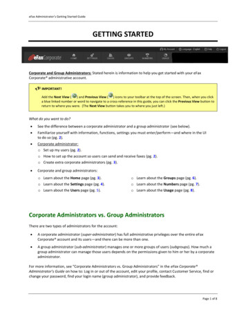
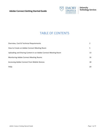
N2200 Series Hardware OverviewDell EMC Networking N2200-ON Series SwitchHardwareThis section contains information about device characteristics and modularhardware configurations for the Dell EMC Networking N2200 Seriesswitches.N2200-ON Series Front PanelThe Dell EMC Networking N2224X-ON/N2224PX-ON/N2248XON/N2248PX-ON switch front panels include the following features: 24 or 48 RJ-45 10/100/1000/2500BASE-T ports Four SFP28 10G/25GBASE-X ports Two QSFP 40G stacking ports RJ-45 and Type-B micro USB 3.0 console ports Reset button Port and system LEDs Stack Master LED and Stack Number Display Type-A USB 3.0 port for storage Out-of-band Ethernet interfaceThe following images show a representative front panel of the Dell EMCNetworking switch.4
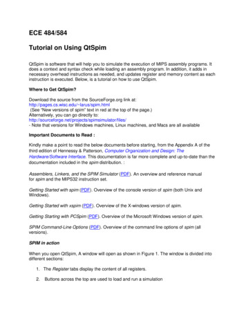
Figure 1-1. Dell EMC Networking N2248PX-ON Switch (Front Panel)N2200-ON Series Rear PanelThe Dell EMC Networking N2200-ON Series back panel has two 40G QSFPstacking ports in the rear. It also has two slots for power supplies, and two(N2224X-ON/N2224PX-ON) or three (N2248X-ON/N2248PX-ON) hot-swapfan trays.Figure 1-2. Dell EMC Networking N2248PX Switch (Rear Panel)N2200X-ON Series Switch PortsThe Dell EMC Networking N2200X-ON Series front panel provides 24 or 4810/100/1000/2500BASE-T Ethernet RJ-45 ports that support auto-negotiationfor speed, flow control, and duplex. Dell EMC Networking N2200X-ONSeries switch front panel 2.5G ports operate in full-duplex at all speeds orhalf-duplex at 10/100 Mbps speeds. The Dell EMC Networking N2200X-ONSeries switch models support four 10G/25G SFP28 ports and two 40G QSFPstacking ports. Dell-qualified transceivers are sold separately.The front-panel switch ports have the following characteristics: The switch automatically detects the difference between crossed andstraight-through cables on RJ-45 ports and automatically chooses the MDIor MDIX configuration to match the other end. The 10/100/1000/2500BASE-T Ethernet RJ-45 ports support full-duplexmode 10/100/1000/2500 Mbps speeds or half-duplex 10/100 Mbps speedson standard Category 5 UTP cable. 2500BASE-T operation requires theuse of auto-negotiation. SFP28 ports support Dell-qualified transceivers utilizing 25GBASE-SR,25GBASE-LR, 25GBASE-CR, 25GBASE-CR-S or 25GBASE-ERtechnologies. SFP28 ports support SFP fiber transceivers and SFP copper twin-ax or DAC technology operating at 10G speeds in full-duplex5
mode. All four SFP28 ports must be configured to operate at the samespeed. 25GBASE-CR and 10G-BASE-CR modes (copper twin-ax or DACcables) require the use of auto-negotiation. The default behavior is to log a message and generate an SNMP trap oninsertion or removal of a transceiver that is not qualified by Dell. Themessage and trap can be suppressed by using the service unsupportedtransceiver command.On the N2224X-ON/N2224PX-ON switches, ports 1-12 may be configured tosupport 10M/100M half-duplex.On the N2248X-ON switches, ports 5-36 may be configured to support10M/100M half-duplex.N2200-ON SFP28 ports may be configured to operate using SFP transceivers using the speed 10000 command for fiber media or the speedauto 10000 command for copper media. All four SFP28 ports must beconfigured to operate at the same speed. A mix of SFP and SFP28transceivers or speeds is not supported. The switch UI does not enforce thisrestriction.N2200-ON Series Console PortThe console port provides serial communication capabilities, which allowscommunication using RS-232 protocol. The serial port provides a directconnection to the switch and allows access to the CLI from a consoleterminal connected to the port through the provided serial cable (with RJ-45YOST to female DB-9 connectors). The console port is separatelyconfigurable and can be run as an asynchronous link from 1200 baud to115,200 baud. The Dell CLI only supports changing the speed. The defaultsare 115,200 baud rate, 8 data bits, no parity, 1 stop bit, no flow control.6
Figure 1-3. Dell EMC Networking N2248 Console PortA separate USB micro type B port is also available for console access to theCPU CLI. RS-232 emulation over USB is supported on this port. A driver mayneed to be installed to support the RS-232 emulation. Only one of theconsole ports may be used at a time.N2200-ON Series USB PortThe Type-A, female USB port supports a USB 3.0-compliant flash memorydrive. The Dell EMC Networking N-Series switch can read or write to a flashdrive with a single partition formatted as FAT-32. Use a USB flash drive tocopy switch configuration files and images between the USB flash drive andthe switch. The USB flash drive may be used to move and copy configurationfiles and images to other switches in the network. The system does notsupport the deletion of files on USB flash drives. The USB port does notsupport any other type of USB device.N2200-ON Series Reset ButtonThe reset button is accessed through the pinhole and enables performing ahard or soft reset of the switch. To reset the switch, insert an unbent paperclip or similar tool into the pinhole for four seconds. When the switchcompletes the boot process after the reset, it resumes operation with the mostrecently saved configuration. Any changes made to the running configurationthat were not saved to the startup configuration prior to the reset are lost.7
To clear the configuration and reset the switch, press the reset button for atleast eight seconds. The saved configuration is cleared and the switch reboots.The switch then starts the autoconfiguration process.N2200-ON Series Port and System LEDsThe front panel contains light emitting diodes (LEDs) that indicate thestatus of system temperature, port links, power supplies, fans, stacking, andthe overall system status. A locator beacon capability is also present on thesystem LEDs. See N2200-ON Series LED Definitions for more information.N2200-ON Series Stack Master LED and Stack Number DisplayWhen a switch within a stack is the master unit, the stack master LED is solidgreen. If the stack master LED is off, the stack member is not the master unit.The stack number LCD displays the unit number for the stack member. If aswitch is not part of a stack (in other words, it is a stack of one switch), thestack master LED is illuminated, and the unit number is displayed.N2200-ON Series Power SuppliesThe Dell EMC Networking N2224X-ON/N2248X-ON switches have a fieldreplaceable 550W power supply (DS-550 AC). An additional field-replaceablepower supply may be added to support redundancy.The Dell EMC Networking N2224PX-ON switches have a field-replaceable1050-watt power supply (DPS-1050 AC) feeding up to 16x30W PoE and2x60W devices at full power (712W). The Dell EMC Networking N2248PXON switches have an internal 1050W power supply (DPS-1050 AC) feedingup to 16x30W PoE devices and 1Xx60W at full power (624W).In both PoE models, additional field replaceable 1050W, 1300W, or 1600Wpower supplies are available to support redundancy or to supply full frontpanel demand.Table 1-1 shows power budget data.Table 1-1.Dell EMC Networking N2200PX-ON Series PoE Power Budget LimitOne PSUModel Name8PoE PowerBudgetPowerTurn-on LimitationTwo PSUs (2x1050W)PoE PowerBudgetPowerTurn-on Limitation
Table 1-1. Dell EMC Networking N2200PX-ON Series PoE Power Budget LimitOne PSUTwo PSUs (2x1050W)Dell EMCNetworkingN2224PX-ON712WThe power budget is 1567W712W. The switchcan power all16x30W and 3x60Wports.The power budget is1567W. The switchcan power all16x30W and8x60W ports at fullpower.Dell EMCNetworkingN2248PX-ON624WThe power budget is 1479W624W. The switchcan power 19x30Wor 9x60W ports.The power budget is1479W. The switchcan power 32x30Wand 7x60W ports atfull power.N2200-ON Series LED DefinitionsThis section describes the LEDs on the front and back panels of the switch.Port LEDsEach port on a Dell EMC Networking N2200-ON Series switch includes twoLEDs. One LED is on the left side of the port, and the second LED is on theright side of the port. This section describes the LEDs on the switch ports.Each 100/1000/10000BASE-T port has two LEDs. Figure 1-4 illustrates the100/1000/10000BASE-T port LEDs.Figure 1-4. 100/1000/10000BASE-T Port LEDsLink/SPDActivity9
Table 1-2 shows the 100/1000/10000BASE-T port LED definitions.Table 1-2.100/1000/10000BASE-T Port LED DefinitionsLEDColorLink/SPD LED OffActivity/PoELED (on PoEswitches)Table 1-3.There is no link.Solid yellowThe port is operating at 10/100 Mbps.Solid greenThe port is operating at 1000 Mbps.OffThere is no current transmit/receive activityand PoE power is off.Blinking greenThe port is actively transmitting/receiving andPoE power is off.Blinking yellowThe port is actively transmitting/receiving andPoE power is on.Solid yellowThere is no current transmit/receive activityand PoE power is on.2500BASE-T Port LED DefinitionsLEDColorLink/SPD LED Off(Left bi-colorSolid greenLED)Solid amberActivity/PoELED(Right bi-colorLED)10DefinitionDefinitionThere is no link.The port is operating at 2.5 Gbps.The port is operating at 100 Mbps or 1 Gbps.OffThere is no current transmit/receive activity,and PoE power is off.Blinking greenThe port is actively transmitting/receiving, andPoE power is off.Blinking amberThe port is actively transmitting/receiving, andPoE power is on.Solid amberThere is no current transmit/receive activity,and PoE power is on.
Table 1-4. SFP Port LED DefinitionsLEDColorLink/SPD LED Off(Left bi-colorSolid greenLED)Solid amberActivity LED(Right singlecolor LED)DefinitionThere is no link.The port is operating at 10 Gbps.The port is operating at 1 Gbps.OffThere is no current transmit/receive activity.Blinking greenThe port is actively transmitting/receiving.Table 1-5. QSFP Port LED DefinitionsLEDColorDefinitionLink/SPD LED Off(Left singleSolid greencolor LED)There is no link.Activity LED(Right singlecolor LED)OffThere is no current transmit/receive activity.Blinking greenThe port is actively transmitting/receiving.The port is operating at 40 Gbps.Stacking Port LEDsTable 1-6. Stacking Port LED DefinitionsLEDColorDefinitionLink LEDOffThere is no link.Solid greenThe port is actively transmitting/receiving.OffThere is no current transmit/receive activity.Blinking greenThe port is actively transmitting/receiving.Activity LED11
Console Port LEDsTable 1-7.Console Port LED DefinitionsLEDColorLink/SPD LED OffSolid greenDefinitionThere is no link.A link is present.System LEDsThe system LEDs, located on the front panel, provide information about thepower supplies, thermal conditions, and diagnostics.Table 1-8 shows the System LED definitions for the Dell EMC NetworkingN2200 switches.Table 1-8.N2200-ON Series System LED DefinitionsLEDColorDefinitionStatusSolid greenNormal operation.Blinking greenThe switch is booting.Solid amberMajor fault. Displays summary of all majorfaults within the switch.Flashing amber Minor fault. Displays summary of all minorfaults within the switch.PowerSolid redA critical system error has occurred.Blinking redA noncritical system error occurred (fan orpower supply failure).OffThere is no power or the switch has experienceda power failure.Solid greenPower to the switch is on.Solid amberPOST in progress.Flashing amber Power supply fault.FanSolid greenThe fan is powered and is operating at theexpected RPM.Flashing amber A fan fault has occurred.12
Table 1-8. N2200-ON Series System LED Definitions (Continued)LEDColorDefinitionSystem BeaconOffLocator function is not enabled.Flashing blueLocation function is enabled.OffThe switch is not stack master.Solid greenThe switch is master for the stack or astandalone unit.–Switch ID within the stack.Stack MasterStack No.N2200 InstallationSite PreparationN2200 Series switches can be mounted in a standard 48.26 cm (19-inch) rackor placed on a flat surface.Make sure that the chosen installation location meets the following siterequirements: Power — The switch is installed near an easily accessible 100–240 VAC,50–60 Hz outlet. Clearance — There is adequate front and rear clearance for operatoraccess. Allow clearance for cabling, power connections, and ventilation. Cabling — The cabling is routed to avoid sources of electrical noise suchas radio transmitters, broadcast amplifiers, power lines, and fluorescentlighting fixtures. Ambient Temperature — The ambient switch operating temperaturerange is 0 to 45ºC (32 to 113ºF) at a relative humidity of up to 95 percent,non-condensing.NOTE: Decrease the maximum temperature by 1 C (1.8 F) per 300 m (985 ft.) above900m (2955 ft.). Relative Humidity — The operating relative humidity is 8% to 85%(noncondensing) with a maximum humidity gradation of 10% per hour.13
Unpacking the N2200 SwitchPackage ContentsWhen unpacking each switch, make sure that the following items areincluded: One Dell Networking switch One RJ-45 to DB-9 female cable One rack-mount kit (N2200) for rack installation, two mounting brackets,bolts, and cage nuts One set of self-adhesive rubber pads for the free-standing switch (four padsare included)Unpacking StepsNOTE: Before unpacking the switch, inspect the container and immediately reportany evidence of damage.1 Place the container on a clean, flat surface and cut all straps securing thecontainer.2 Open the container or remove the container top.3 Carefully remove the switch from the container and place it on a secureand clean surface.4 Remove all packing material.5 Inspect the product and accessories for damage.Rack Mounting a N2200 SwitchWARNING: Read the safety information in the Safety and Regulatory Informationas well as the safety information for other switches that connect to or support theswitch.The AC power connector is on the back panel of the switch.Installing in a RackWARNING: Do not use rack mounting kits to suspend the switch from under atable or desk, or attach it to a wall.14
CAUTION: Disconnect all cables from the switch before continuing. Remove allself-adhesive pads from the underside of the switch, if they have been attached.CAUTION: When mounting multiple switches into a rack, mount the switchesfrom the bottom up.1 Place the supplied rack-mounting bracket on one side of the switch,ensuring that the mounting holes on the switch line up to the mountingholes in the rack-mounting bracket. Figure 1-5 illustrates where to mountthe brackets.Figure 1-5. Attaching the Brackets2 Insert the supplied bolts into the rack-mounting holes and tighten with ascrewdriver.3 Repeat the process for the rack-mounting bracket on the other side of theswitch.4 Insert the switch into the 48.26 cm (19 inch) rack, ensuring that the rackmounting holes on the switch line up to the mounting holes in the rack.5 Secure the switch to the rack with either the rack bolts or cage nuts andcage-nut bolts with washers (depending on the kind of rack you have).Fasten the bolts on bottom before fastening the bolts on top.CAUTION: Make sure that the supplied rack bolts fit the pre-threaded holes in therack.NOTE: Make sure that the ventilation holes are not obstructed.15
Installing as a Free-standing SwitchNOTE: We strongly recommend mounting the switch in a rack.Install the switch on a flat surface if you are not installing it in a rack. Thesurface must be able to support the weight of the switch and the switchcables. The switch is supplied with four self-adhesive rubber pads.1 Attach the self-adhesive rubber pads on each location marked on thebottom of the switch.2 Set the switch on a flat surface, and make sure that it has properventilation by leaving 5 cm (2 inches) on each side and 13 cm (5 inches) atthe back.Stacking Multiple N2200 SwitchesYou can stack N2200 switches up to 12 switches high using the QSFP portslocated on the rear of the switch. N2200 switches support stacking only withother N2200 series switches. When multiple switches are connected togetherthrough the stack ports, they operate as a single unit with up to 576 frontpanel ports. The stack operates and is managed as a single entity.NOTE: If you are installing a stack of switches, you need to assemble and cable thestack before powering up and configuring it. When a stack is powered up for thefirst time, the switches elect a Master Switch, which may occupy any location inthe stack. The Master LED on the front panel is illuminated on the master unit.Creating a Switch StackCreate a stack by connecting adjacent units using the QSFP stacking ports onthe back panel of the switch. Figure 1-6 on page 17 shows the switchesconnected in a ring topology, which is the recommended topology for a stack.1 Connect one of the QSFP cables into either of the stacking ports of thetop switch and the switch directly below it.If necessary, use a separately purchased, longer (1 meter or 3 meter) QSFPcable to connect the switches.2 Repeat this process until all of the devices are connected.3 Use the remaining stacking cable to connect the two remaining stackingports together so that a ring topology is assembled.16
Figure 1-6. Connecting a Stack of SwitchesUnit 1Unit 2Unit 3The stack in Figure 1-6 is connected in a ring topology and has the followingphysical connections between the switches: The bottom QSFP port on Unit 1 is connected to the top QSFP port onUnit 2. The bottom QSFP port on Unit 2 is connected to the top QSFP port onUnit 3. The bottom QSFP port on Unit 3 is connected to the top QSFP port onUnit 1.Stacking StandbyThe stacking feature supports a Standby or backup unit that assumes theMaster unit role if the Master unit in the stack fails. As soon as a Masterfailure is detected in the stack, the Standby unit initializes the control planeand enables all other stack units with the current configuration. The Standbyunit maintains a synchronized copy of the running configuration for thestack. The Standby unit is automatically selected in the stack; however, youcan use the CLI to select a different stack member as Standby. See the User’sConfiguration Guide or the CLI Reference Guide for more information.17
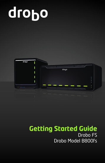
Starting and Configuring the N2200SwitchThe following flow chart provides an overview of the steps you use to performthe initial configuration after the switch is unpacked and mounted.Figure 1-7. Installation and Configuration Flow Chart18
Connecting a N2200 Switch to a TerminalAfter completing all external connections, connect a terminal to a switch toconfigure the switch.NOTE: Read the Release Notes for this product before proceeding. You candownload the Release Notes from the Dell Support website atdell.com/support/manuals.NOTE: We recommend that you obtain the most recent version of the userdocumentation from the Dell Support website at dell.com/support/manuals.To monitor and configure the switch via serial console, use the console porton the front panel of the switch (see Figure 1-8 on page 20) to connect it to aVT100 terminal or to a computer running VT100 terminal emulationsoftware. The console port is implemented as a data terminal equipment(DTE) connector.The following equipment is required to use the console port: VT100-compatible terminal or a computer with a serial port runningVT100 terminal emulation software, such as Microsoft HyperTerminal. A serial cable (provided) with an RJ-45 connector for the console port andDB-9 connector for the terminal.Perform the following tasks to connect a terminal to the switch console port:1 Connect the DB-9 connector on the serial cable to the terminal orcomputer running VT100 terminal emulation software.2 Configure the terminal emulation software as follows:aSelect the appropriate serial port (for example, COM 1) to connect tothe console.bSet the data rate to 115,200 baud.cSet the data format to 8 data bits, 1 stop bit, and no parity.dSet the flow control to none.eSet the terminal emulation mode to VT100.fSelect Terminal keys for Function, Arrow, and Ctrl keys. Make surethat the setting is for Terminal keys (not Microsoft Windows keys).19
3 Connect the RJ-45 connector on the cable directly to the switch consoleport. The Dell Networking console port is located on the right side of thefront panel and is labeled with a O O symbol, as shown in Figure 1-8 onpage 20.NOTE: Serial console access to the stack manager is available from anyserial port via the local CLI. Only one serial console session at a time issupported.Figure 1-8. N2200 Front Panel with Console PortConsole PortConnecting a N2200 Switch to a Power SourceCAUTION: Read the safety information in the Safety and Regulatory Informationmanual as well as the safety information for other switches that connect to orsupport the switch.All N2200 models have one internal power supply. The power receptacles areon the back panel.AC and DC Power Connection1 Make sure that the switch console port is connected to a VT100 terminalor VT100 terminal emulator via the RJ-45 to DB-9 female cable.2 Using a 5-foot (1.5 m) standard power cable with safety ground connected,connect the power cable to the AC main receptacle located on the backpanel (see Figure 1-9 on page 21).3 Connect the power cable to a grounded AC outlet.20
4 If you are using a redundant or external DC power supply, such as the DellNetworking RPS720, connect the DC power cable to the DC receptaclelocated on the back panel. In Figure 1-9 on page 21, the redundant powersupply feed is in the middle and is labeled RPS.Figure 1-9. AC and DC Power Connection to an N2200 SwitchTo DC Power Source (Optional)To AC Power SourceBooting the N2200 SwitchWhen the power is turned on with the local terminal already connected, theswitch goes through a power-on self-test (POST). POST runs every time theswitch is initialized and checks hardware components to determine if theswitch is fully operational before completely booting. If POST detects acritical problem, the program flow stops. If POST passes successfully, validfirmware is loaded into RAM. POST messages are displayed on the terminaland indicate test success or failure. The boot process runs for approximately60 seconds.You can invoke the Boot menu after the first part of the POST is completed.From the Boot menu, you can perform configuration tasks such as resettingthe system to factory defaults, activating the backup image, or recovering apassword. For more information about the Boot menu functions, see the CLIReference Guide.Performing the N2200 Initial ConfigurationThe initial configuration procedure is based on the following assumptions: The Dell Networking switch was never configured before.21
The Dell Networking switch booted successfully. The console connection was established, and the Dell Easy Setup Wizardprompt appears on the screen of a VT100 terminal or terminal equivalent.The initial switch configuration is performed through the console port. Afterthe initial configuration, you can manage the switch from the alreadyconnected console port or remotely through an interface defined during theinitial configuration.NOTE: The switch is not configured with a default user name, password, or IPaddress.Before setting up the initial configuration of the switch, obtain the followinginformation from your network administrator: The IP address to be assigned to the management interface. The IP subnet mask for the network. The IP address of the management interface default gateway.These settings are necessary to allow the remote management of the switchthrough Telnet (Telnet client) or HTTP (Web browser).Enabling Remote ManagementThe N2200-ON switch’s front panel contains a Gigabit Ethernet port of OOBmanagement. The OOB port is located to the right of the console port. Onthe N2200-ON switches, you can use the OOB port or any of the switch portson the front panel for in-band management. By default, all in-band ports aremembers of VLAN 1.The Dell Easy Setup Wizard includes prompts to configure networkinformation for the out-of-band interface on the N2200 switch. You canassign a static IP address and subnet mask or enable DHCP and allow anetwork DHCP server to assign the information.See the CLI Reference Guide for information about the CLI commands youuse to configure network information.22
Initial Configuration ProcedureYou can perform the initial configuration by using the Dell Easy SetupWizard or by using the CLI. The wizard automatically starts when the switchconfiguration file is empty. You can exit the wizard at any point by entering[ctrl z], but
Figure 1-1. Dell EMC Networking N2248PX-ON Switch (Front Panel) N2200-ON Series Rear Panel The Dell EMC Networking N2200-ON Series back panel has two 40G QSFP stacking ports in the rear. It also has two slots for power supplies, and two (N2224X-ON/N2224PX-ON) or three (N2248X-ON/N2248PX-ON) hot-swap fan trays. Figure 1-2.