Transcription
520 (T‐H2) and 320 (T‐H2S)Installation Manual and Owner’s GuideANSI Z21.10.3 and CSA 4.3520 (T‐H2) modelsonlyIf the information in theseinstructions is not followedexactly, a fire or explosionWARNINGmay result causingproperty damage, personal injury or death.‐Do not store or use gasoline or otherflammable vapors and liquids in the vicinity ofthis or any other appliance.Gas Tankless Water HeaterDirect Vent Indoor models (520 Indoor (T‐H2‐DV),320 Indoor (T‐H2S‐DV))Outdoor models (520 Outdoor (T‐H2‐OS),320 Outdoor (T‐H2S‐OS))Suitable for potable water heating and space‐heating *‐WHAT TO DO IF YOU SMELL GAS Do not try to light any appliance. Do not touch any electric switch, do notuse any phone in your building. Immediately call your gas supplier from aneighbor's phone. Follow the gassupplier's instructions. If you cannot reach your gas supplier, callthe fire department.‐Installation and service must be performedby a qualified installer, service agency or thegas supplier.*Please refer to local codes for space‐heating compliance.FEATURING ENDLESS HOT WATER ON DEMAND USAGE COMPACT, SPACE SAVING ENERGY CONSERVATION COMPUTERIZED SAFETY NO PILOT LIGHT EASY‐LINK SYSTEMIf you have any questions, pleasecall or write to:500 Tennessee Waltz ParkwayAshland City, TN 37015Toll Free: 1‐ 877‐737‐2840
ContentsSPECIFICATIONS520 (T‐H2) and 320 (T‐H2S) modelsNaturalPropanePropaneGas ConnectionWater ConnectionsCondensate Drain PortConnectionWater Pressure*Natural GasInlet PressurePropaneInlet Pressure520 DirectVent Indoor(T‐H2‐DV)520 Outdoor(T‐H2‐OS)320 DirectVent Indoor(T‐H2S‐DV)320 Outdoor(T‐H2S‐OS)Manifold Pressure**SPECIFICATIONS . 2INTRODUCTION . 3SAFETY GUIDELINES . .4INSTALLATION . . 5General . 6Included Accessories . 6Optional items . . 7Warning for Installations . . 8High‐altitude Installations 9Installation for outdoor models . 9Installation for direct vent indoormodels 10Venting Instructions . 10Gas Supply / Gas Pipe Sizing . 17Water Connections . . 19Pressure Relief Valve 20Condensate drain . 20Electrical Connections . 22Remote Controller Connection . 23Pump Control Connections . 24Pump Control Mode . 25Easy‐Link System . 27APPLICATIONS. 31Space Heating . . 31INITIAL OPERATION. . 33Gas InputInstallation ManualWeightDimensionsIgnitionSupplyOwner’s GuideOPERATING SAFETY 34NORMAL OPERATION 36General . . . 36Temperature settings. . . 36Flow . 38Freeze Protection System . 38Maintenance and Service 39Unit Draining and Filter Cleaning 39TROUBLESHOOTING . 40General . . . 40Error codes. . . 42COMPONENTS DIAGRAM . 44PARTS LIST . 47OUTPUT TEMPERATURE CHART . 50LIMITED WARRANTY . 51ElectricConsumptionMin: 13,000 Btu/hMax: 199,000 Btu/hMin: 13,000 Btu/hMax: 180,000 Btu/h¾” NPT¾” NPT½” NPT15 ‐ 150 psiMin. 5.0” WCMax. 10.5” WCMin. 8.0” WCMax. 14.0” WCNatural: 3.2” WCPropane: 5.5” WCNatural: 2.7” WCPropane: 4.6” WCNatural: 2.5” WCPropane: 4.3” WCNatural: 1.9” WCPropane: 3.6” WC73 lbs.(Direct Vent Indoor models)71 lbs. (Outdoor models)H25.6” x W18.5” x D12.4”Electric Ignition120 VAC / 60 HzOperation of the152 WDirect Vent(1.27A)Indoor modelsOperation of the 102WOutdoor models (0.85A)8.2 WStandby(0.07A)Freeze‐207 WProtection(1.73A)*40 psi or above is recommended for maximum flow.**The Manifold Pressure is the factory setting and generallyshould not need adjustment.NOTE Check the rating plate to ensure this product matches yourspecifications.In accordance with ANZI Z21.10.3, CO emission does notexceed 400 PPM for normal input.The manufacturer reserves the right to discontinue, or change atany time, specifications or designs without notice and withoutincurring obligations.2 Page
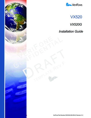
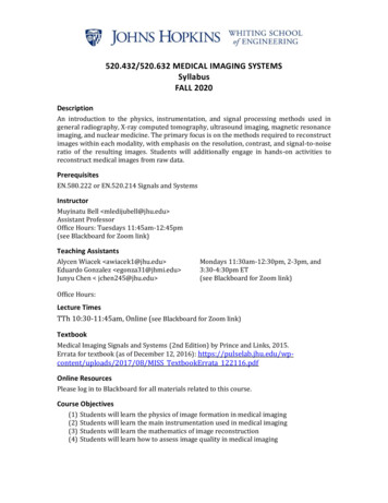
IntroductionINTRODUCTION This manual provides information necessary for the installation, operation, andmaintenance of the water heater. The model description is listed on the rating plate which is attached to the side panel ofthe water heater. Please read all installation instructions completely before installing this product. If you have any problems or questions regarding this equipment, consult with themanufacturer or its local representative. This equipment is an on‐demand, tankless water heaters designed to efficiently supplyendless hot water for your needs. The water heater is high efficiency models with an in‐build secondary heat exchangerthat absorbs latent heat from the exhaust gas. The principle behind the water heater is simple:ExhaustIntake portSecondary heat exchangerThermistorPrimary heatexchangerBypass valveWater control valveBurnerFlow sensorFan motorThermistorGas ValveThermistorPCBGasHot Water OutletCondensatedrain portCold Water Outlet*This diagramillustrates tanklesswater heater designconcepts only anddoes not accuratelyrepresent to the waterheater’s physicaldescription.1. A hot water tap is turned on.2. Water enters the heater.3. The water flow sensor detects the water flow.4. The computer automatically ignites the burner.5. Water circulates through the heat exchanger and then gets hot.6. The computer will modulate the gas supply valve and water flow to produce the rightamount of hot water at the correct temperature.7. When the tap is turned off, the unit shuts down.3 Page
Safety GuidelinesSAFETY GUIDELINESGENERAL1.2.3.4.5.Follow all local codes, or in the absence of local codes, follow the most recent edition of theNational Fuel Gas Code: ANSI Z223.1/NFPA 54 in the USA or CAN/CSA B149.1 Natural Gas, PropaneInstallation Code in Canada.Properly ground the unit in accordance with all local codes or in the absence of local codes, withthe National Electrical Codes: ANSI/NFPA 70 in the USA or CSA standard C22.1 Canada ElectricalCode Part 1 in Canada.Carefully plan where you intend to install the water heater. Please ensure: Your water heater will have enough combustible air and properventilation. Locate your heater where water leakage will not damagesurrounding areas (please refer to p. 5).Check the rating plate for the correct GAS TYPE, GAS PRESSURE, WATERPRESSURE and ELECTRIC RATING.*If this unit does not match your requirements, do not install andconsult with the manufacturer.If any problem should occur, turn off all hot water taps and turn off thegas. Then call a trained technician or the Gas Company or themanufacturer.RATING PLATEWARNING Water temperatures over 125 F (52 C) can cause severe burns instantly or death from scalding.The water temperature is set at 120 F (49 C) from the factory to minimize any scalding risk.Before bathing or showering always check the water temperature. Prohibited Do not store or use gasoline or other flammables, vapors, or liquids in the vicinityof this appliance.Do not reverse the water and/or gas connections as this will damage the gasvalves and can cause severe injury or death. Follow the diagram on p. 19 wheninstalling your water heater:Do not use this appliance if any part has been in contact with or been immersed inwater. Immediately call a licensed plumber, a licensed gas fitter, or a professionalservice technician to inspect and/or service the unit if necessary.Do not disconnect the electrical supply if the ambient temperature will dropbelow freezing. The Freeze Prevention System only works if the unit has electricalpower. The warranty will not be covered if the heat exchanger is damaged due tofreezing. Refer to the section on the Freeze Prevention System on p. 38 for moreinformation.4 Page
InstallationINSTALLATIONAll gas water heaters require careful and correct installation to ensure safe and efficient operation. Thismanual must be followed exactly. Read the “Safety Guidelines” section at the beginning of this manual.WARNING Installation and service must be performed by a qualified installer (forexample, a licensed plumber or gas fitter), otherwise the warranty will bevoid. The installer (licensed professional) is responsible for the correct installationof the water heater and for compliance with all national, state/provincial,and local codes.PLEASE READ THIS MANUAL CAREFULLY AND FOLLOW ALL DIRECTIONS. The warranty will not cover damage caused by water quality. CAUTION Only potable water or potable water / glycol mixtures can be used with thiswater heater. Do not introduce pool or spa water, or any chemicallytreated water into the water heater.Water hardness levels must not exceed 7 grains per gallon (120 ppm) forsingle family domestic applications or more than 4 grains per gallon (70ppm) for all other types of applications. Water hardness leads to scaleformation and may affect/damage the water heater. Hard water scalingmust be avoided or controlled by proper water treatment.Water pH levels must be between 6.5 and 8.5Well water must be treated. Although this water heater is designed to operate with minimal sound, themanufacturer does not recommend installing the unit on a wall adjacent to abedroom, or a room that is intended for quiet study or meditation, etc. Locate your heater close to a drain where water leakage will not do damage tosurrounding areas. As with any water heating appliance, the potential forleakage at some time in the life of the product does exist. The manufacturerwill not be responsible for any water damage that may occur. If you install adrain pan under the unit, ensure that it will not restrict the combustion air flow.WARNING The water heater is high efficiency products that create condensation. Acondensation drain tube must be installed with these models to dischargecondensate into a drain outlet. For more information, refer to p. 20. The manufacturer does not recommend installing the Direct Vent Indoormodels in an attic due to safety issues. If you install your Direct Vent Indoormodels in an attic: Make sure your unit will have enough combustion air and properventilation. Keep the area around you’re the water heater clean. When dust collects onthe flame sensor, the water heater will shut down on errors. Locate unit for easy access for service and maintenance. A drain pan, or other means of protection against water damage, isrequired to be installed under the water heater in case of leaks.5 Page
InstallationGENERAL1. Follow all local codes, or in the absence of local codes, follow the most recent edition of theNational Fuel Gas Code: ANSI Z223.1/NFPA 54 in the USA or CAN/CSA B149.1 Natural Gas,Propane Installation Code in Canada.2. The manifold gas pressure is preset at the factory. It is computer controlled and should notneed adjustment.3. Maintain proper space for servicing. Install the unit so that it can be connected or removedeasily. Refer to p. 8, p.9 and p. 10 for proper clearances.4. The electrical connection requires a means of disconnection, to terminate power to the waterheater for servicing and safety purposes.5. If you will be installing the unit in a contaminated area with a high level of dust, sand, flour,aerosols or other contaminants/chemicals, they can become airborne and enter and build upwithin the fan and burner causing damage to the unit.6. Particles from flour, aerosols, and other contaminants may clog the air vent or reduce thefunctions of the rotating fan and cause improper burning of the gas. Regularly ensure that thearea around the unit is dust‐ or debris‐free; regular maintenance is recommended for thesetypes of environment.7. Do not install the unit where the exhaust vent is pointing into any opening in a building or wherethe noise may disturb your neighbors. Make sure the vent termination meets the requireddistance by local code from any doorway or opening to prevent exhaust from entering a building(refer to p. 15).INCLUDED ACCESSORIESCheck that the installation manual, the communication cable, the product registration card and the PVCadaptor are included with the unit (the adaptor comes with the Direct Vent Indoor models only.For details on how to connect the adaptor, refer to P.14.1. Manual2. Communication cable520 (T‐H2) models onlyQty: 13. Product Registration CardQty: 14. PVC adaptorDirect Vent Indoor models onlyQty: 1Qty: 16 Page
InstallationOPTIONAL ITEMS1. Temperature Remote Controller: 9007603005 (TM‐RE30)The Temperature Remote Controller has two functions. It allowsthe output temperature from the water heater to be adjustedwithin the range of 100 F to 185 F, and it also works as adiagnostic tool that will give a concise error code whenever thereis a problem with the unit. The temperature options are 100 F,105 F, 110 F, 115 F, 120 F, 125 F, 130 F, 135 F, 140 F, 145 F,150 F, 155 F, 160 F, 165 F, 170 F, 175 F, 180 F and 185 F. See thetrouble shooting section for information on possible error codes.2. Pipe cover: 9007606005 (TH‐PC02)The Pipe cover protects the plumbing pipes to the water heaterfrom unexpected adjustments. This pipe cover is fixed to thebottom of the water heater, which hides the plumbing andimproves the visual aspects of the whole installation for the waterheater.3. Wall thimble with Termination: 9007608005 (TK‐KPWL4) and 9007609005 )HoodTermination9007609005(TK‐KPWH4)These terminations are used when venting out through the wall andare compatible with the T‐Vent pipe system.These terminations are special stainless steel vents for gas appliancesand are UL listed as Category II, III and IV. There are two types ofterminations: the Louver termination and the Hood termination. Fordifferent wall thicknesses, there are two ranges of lengths available(refer to the venting brochure for details).Install these vent terminations in accordance with their installationinstructions and any applicable local codes.4. Neutralizer kit: 9007607005 (TH‐NT01)The Neutralizer assembly neutralizes the condensate (acidicwater) that forms in the secondary heat exchanger of thewater heater.It connects to the condensate drain port of the water heater byusing connectors included with the neutralizer kit. Refer to p.21 for the details.7 Page
InstallationWARNING FOR INSTALLATIONSFOR YOUR SAFETY, READ BEFORE INSTALLATION:Do not install the heater where water, debris orflammable vapors may get into the flue terminal.This may cause damage to the heater and voidthe warranty.Do not have the vent terminal pointing towardany opening into a building. Do not locate yourheater in a pit or location where gas and watercan accumulate.ProhibitedProhibitedDo not install this water heater under anoverhang less than 3 feet from its top or eaves.The area under an overhang must be open tothree sides. (Outdoor models only)Do not install the water heater vent terminatorwithin 1 ft. in the USA of any air intake or buildingopening, and with in 3 ft. in Canada of any airintake or building opening. (Outdoor modelsonly) (Refer to p.15)Do not install next to a dryer or any source ofairborne debris that can be trapped inside thecombustion chamber, unless the system is directvented.8 Page
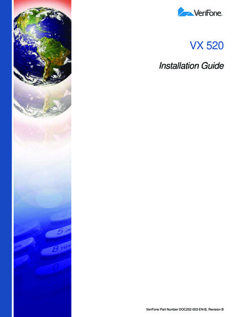
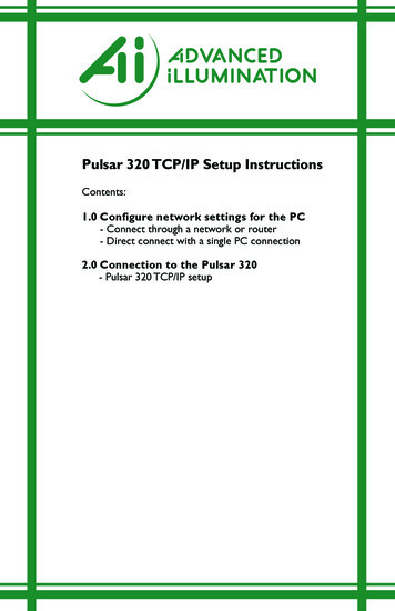
InstallationHIGH‐ALTITUDE INSTALLATIONSCheck the elevation where your water heater is installed. Set dipswitches shown in the table belowdepending on the altitude. These dipswitches (No. 5 and No. 6) are on the computer board on the leftbank only.Left bank of dipswitches2,500 to 4,000 ft 4,000 to 5,000 ft Over 5,000 ftONOFFOFFONNONOSwitch No.5Switch No.60 to 2,500 ft(DEFAULT)OFFOFFNOAltitude1 2 3 4 5 6 7 8 9 101 2 3 4 5 6 7 8 9 101 2 3 4 5 6 7 8 9 10Consultour TechnicalServicesDepartmentat 1‐877‐737‐2840The dark squares indicate the direction thedipswitches should be set to.DO NOT adjust any dipswitches on the right bank.Left bank of dipswitchesINSTALLATION FOR OUTDOOR MODELS1. Install the Outdoor model only in areas with mild, temperate climates.2. The Outdoor model shall be wall‐mounted or mounted on a stand. Locate the Outdoor model inan open, unroofed area and maintain the following minimum clearances:Top 36” There is a 3” clearance fromthe left and right sides of theunit to combustible and non‐combustiblesurfaces. However, if anyportion or area of the surfaceis exposed to the exhaustfumes (i.e. directly to the sidesof the vent cap), that surfacemust be at least 24” away. Keep the clearances.Side 3”Back 0.5”Side 3”Front 24”Bottom 12”9 Page
InstallationINSTALLATION FOR DIRECT VENT INDOOR MODELSThe Direct Vent Indoor models are equipped with a thermistor and hi‐limit switch for the exhaust gas,detecting excess temperatures within the flue and enabling the unit to safely stop operations if needed.These components are always monitoring exhaust gas conditions in order to prevent heat damage toPVC (Plastic) venting if PVC is used.If the exhaust gas temperature exceeds 140 F, these components will enable the unit to safely stopoperations. (For the Outdoor model, these components are not available since there’s no exhaustventing required.)Top 12” The Direct Vent Indoor model requires a4” make‐up intake air supply pipe. Theintake pipe must be sealed airtight. Air supply pipe can be made of ABS, PVC,Back 0.5”galvanized steel, corrugated stainlesssteel, or Category lll / IV stainless steel.Side 3” Sidewall venting is recommended for theDirect Vent Indoor model. Verticalventing (roof termination) is acceptable.Side 3” The manufacturer recommendsFront 4”running the exhaust vent and the(24” Recommendedintake pipe as parallel as possible.for Maintenance) The PVC adaptor is used to make theconnection between the Direct VentBottom 12”Indoor model vent collar and PVCvent pipe easier and for maintenancepurposes.Keep the clearances.VENTING INSTRUCTIONS‐General‐Improper venting of this appliance can result in excessive levels of carbon monoxidewhich can result in severe personal injury or death.WARNINGWhen installing the vent system, all applicable national and local codes must befollowed. If you install thimbles, fire stops or other protective devices and theypenetrate any combustible or noncombustible construction, be sure to follow allapplicable national and local codes.The Direct Vent Indoor models must be vented in accordance with the section “Venting of Equipment"of the latest edition of the National Fuel Gas Code: ANSI Z223.1/NFPA 54 in the United States and/orSection 7 of the CAN/CSA B149.1 Natural Gas and Propane Installation Code in Canada, as well asapplicable local building codes.The use of venting materials approved for Category III/IV appliances is recommended whenever possible.However, the Direct Vent Indoor models may also be vented with plastic pipe materials such as PVC. Fordetails, please refer to the Exhaust Vent (PVC Vent) section on p. 11. Vent installations in Canada whichutilize plastic vent systems must use venting that complies with ULC S636.10 Page
Installation‐Exhaust vent (PVC and ABS vent) ‐The Direct Vent Indoor models can be connected with PVC or ABS venting (temperature rated up to149 F). However, the manufacturer recommends PVC (or ABS) venting certified to ULC S636 standards.ItemMaterialUnited StatesCanadaSchedule 40 PVCANSI/ASTM D1785Exhaust pipe andPVC‐DWVANSI/ASTM D2665FittingsSchedule 40 CPVCANSI/ASTM F441ULC S636 CertifiedSchedule 40 ABS‐DWVANSI/ASTM D2661Materials OnlyPVCANSI/ASTM D2564Pipe Cement/PrimerCPVCANSI/ASTM F493ABSANSI/ASTM D2235NOTE: Do NOT Use Cellular Foam Core Pipe The maximum length of exhaust vent piping must not exceed 50 ft. for 4” venting and 25 ft. for3” venting (deducting 5 ft. for each elbow used in the venting system). Do not use more than 5elbows for 4” venting and 2 elbows for 3” venting. When the horizontal vent run exceeds 5 ft., support the vent run at 3 ft. intervals with overheadhangers.Diameter3”4”Max. No. of Elbow25Max. Vertical and Horizontal (Total) Vent Length25 ft.50 ft.* For each elbow added, deduct 5 ft. from max. vent length.Max. Vertical or Horizontal Length3” venting4” venting025 ft.50 ft.120 ft.45 ft.215 ft.40 ft.5N/A25 ft.Excludes elbow termination, rain caps, or the 3” PVC Concentric TerminationNo. of ElbowsFor details on the vent connection to the Direct Vent Indoor models, refer to P.14‐Exhaust vent (Stainless steel vent)‐This is a Category IV appliance and must be vented accordingly. The vent system must be sealed air tight.All seams and joints without gaskets must be sealed with high heat resistant silicone sealant or UL listedaluminum adhesive tape having a minimum temperature rating of 160 F. For best results, a vent systemshould be as short and straight as possible. The Direct Vent Indoor models are a Category IV appliance and must be vented accordingly withany 4” vent approved for use with Category III/IV or Special BH type gas vent.The manufacturer recommends the “T‐Vent” line manufactured by TAKAGI (Refer to Takagi’s“T‐Vent” brochure for details). However, the following are also UL listed manufacturers: ProTechSystems Inc. (FasNSeal), Flex‐L Inc., Z‐Flex Inc. (Z‐Vent III), Metal‐Fab Inc., and Heat‐Fab Inc. (Saf‐T Vent).Follow the vent pipe manufacturer’s instructions when installing the vent pipe.11 Page
InstallationDo not common vent this appliance with any other vented appliance (Do not terminate ventinto a chimney. If the vent must go through the chimney, the vent must run all the way throughthe chimney with Category III / IV approved or Special BH vent pipe).The maximum length of exhaust vent piping must not exceed 50 ft. (deducting 5 ft. for eachelbow used in the venting system). Do not use more than 5 elbows.When the horizontal vent run exceeds 5 ft., support the vent run at 3 ft. intervals with overheadhangars.Diameter4”Max. No. of Elbow5Max. Vertical and Horizontal (Total) Vent Length50 ft.*For each elbow added, deduct 5 ft. from max. Vent length.No. of Elbows0125Max. Vertical or Horizontal Length50 ft.45 ft.40 ft.25 ft.‐Vent termination ‐WARNINGImproper installation can cause nausea or asphyxiation, severe injury or death fromcarbon monoxide and flue gases poisoning. Improper installation will void productwarranty. The vent terminator provides a means of installing vent pipe through the building wall and must belocated in accordance with ANSI Z223.1/NFPA 54, or in Canada with CAN/CSA‐B149.1 and localapplicable codes. A proper sidewall direct‐vent terminator is recommended when the water heater is vented through asidewall.General rules for venting the Direct Vent Indoor models are:1.Place the water heater as close as possible to the vent terminator.2.The vent collar of the water heater must be fastened directly to an unobstructed vent pipe or PVCadaptor.3.Do not weld the vent pipe to the water heater collar.4.Do not cut the vent collar of the unit.5.The weight of the vent stack must not rest on the water heater.6.The vent must be easily removable from the top of the water heater for normal service andinspection of the unit.7.The water heater vent must not be connected to any other gas appliance or vent stack.8.Avoid locating the water heater vent terminator near any air intake devices. These fans can pickup the exhaust flue products from the water heater and return them to the building. This cancreate a health hazard.9.Avoid using an oversized vent pipe or using extremely long runs of the pipe.10. Locate the vent terminator so that it cannot be blocked by any debris, at any time. Most codesrequire that the terminator be at least 12 inches above grade, but the installer may determine if itshould be higher depending on the job site condition and applicable codes.11. For rooftop venting, a rain cap or other form of termination that prevents rain water from enteringinto the water heater must be installed.12 Page
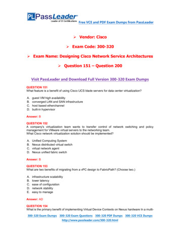
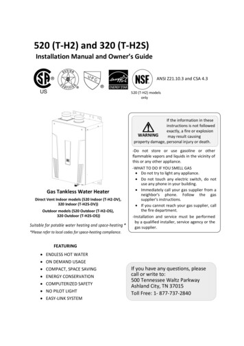
Installation‐PVC Venting Illustrations‐Horizontal Installation Diagram(With elbow terminations)Vertical Installation DiagramWallRoofRoof FlashingFire stopConnection between exhaust vent collar and PVC pipingSee the next page for instructions.Horizontal Installation Diagram(With 3” PVC Concentric Termination)Concentric TerminationWall1” minimumclearanceKeep a 1” clearance between walland the intake section of theconcentric termination. See thediagram to the left.Insert the bird screen included withthe terminationConnection between exhaust vent collar and PVC pipingSee the next page for instructions.How to install PVC venting with the Direct Vent Indoor models(For Exhaust)1. Connect the PVC adaptor* directly on the exhaust vent collar of the water heater.2. Connect a 4” PVC coupler (or 4x3” PVC reducer) to the PVC adaptor.3. From the coupler (or reducer), continue on the rest of the vent run with 4” PVC pipe (or 3” PVCpipe.)13 Page
Installation(For Intake: 4” only)1. Connect a 4” PVC Straight pipe directly on the intake vent collar of the water heater.(For Intake: 3” only)1. Connect a 4” PVC Straight pipe directly on the intake vent collar of the water heater.2. Connect a 4x3” PVC reducer to the 4” PVC Straight pipe.3. From the reducer, continue on the rest of the vent run with 3” PVC pipe.4” vent connection Diagram4” PVC Straightpipe3” vent connection Diagram4” PVC Straight pipe4” PVC coupler4x3” PVC reducerPVC adaptor*Intake vent collar3” PVC StraightpipeExhaust vent collarof the Direct VentIndoor models(Female)4” PVC StraightpipeIntake vent collar3” PVC Straight pipe4x3” PVC reducerPVC adaptor*Exhaust vent collarof the Direct VentIndoor models(Female)*PVC adaptor is included with the Direct Vent Indoor models.‐Stainless steel Venting Illustrations‐Vertical Installation DiagramHorizontal Installation DiagramWallRain CapRoofRoof FlashingSidewall VentTerminator Regarding the clearances from the exhaust terminator tothe air inlet or opening, refer to the next few pages. Follow all vent system manufacturer’s instructions and alllocal codes. Do not common vent or connect any vent from otherappliances to the Direct Vent Indoor models vent. Use 4” Category III/IV approved or Special BH, single ordouble wall stainless steel vent pipe.14 PageFire stop
Installation‐Vent clearances‐CanadaDirect vent andother than DirectVentU.S.ADirect ventOther than Direct Vent1 footAClearance above grade, veranda, porch, deck,or balcony.1 foot1 footBClearance to window or door that may beopened.3 feet1 footC4 feet from below or sideopening. 1 foot fromabove opening.*Clearance to permanently closed window**Vertical clearance to ventilated soffit locatedabove the vent terminator within a horizontalD***distance of 2 feet (61cm) from the center lineof the terminator.E Clearance to unventilated soffit***F Clearance to outside corner***G Clearance to inside corner***Clearance to each side of center line extendedH3 feet**above meter/regulator assemblyIClearance to service regulator vent outlet.3 feet**Clearance to non‐mechanical air supply inlet4 feet from below or sideJ to building or the combustion air inlet to any3 feet1 footopening. 1 foot fromother application.above opening.K Clearance to mechanical air supply inlet.6 feet3 feet3 feetClearance above paved sidewalk or pavedL7 feet*7 feetdriveway located on public property.Clearance under veranda, porch deck, orM1 foot**balcony.*For clearances not specified in ANSI Z223.1 / NFPA 54 or CAN/CSA‐B149.1, please use clearances in accordance withlocal installation codes and the requirement of the gas supplier.15 Page
Installation‐Additional clearances ‐Please follow all local and national codes in regards to proper termination clearances. In the absence ofsuch codes, the following clearances can be used as guidelines. Local codes supersede these guidelines.For sidewall sidecornerExhaust terminationFor multiple sidewall exhaustterminations (e.g. multi‐unitsystems), an exhaust terminationmust be at least 1 ft. away fromanother exhaust termination. Anexhaust termination must also beat least 2 ft. away from an insidecorner (if the adjacent wall is lessthan 2 ft. of length, the minimumrequired distance away from theinside corner will be equal to thelength of that adjacent wall).InsidecornerAir supply inletFor direct‐vent sidewallterminations that use twoseparate penetrations for theintake and exhaust, distancethe intake and exhaustterminations at least 3 ft. awayfrom each other, no matter theorientation.Direct vent terminationFor multiple‐unit, direct‐vent sidewallterminations that combine the intakeand exhaust into a single penetration,space each direct‐vent termination atleast 1 ft. away from each other, nomatter the orientation. A direct‐venttermination must also be at least 2 ft.away from an inside corner (if theadjacent wall is less than 2 ft. oflength, the minimum requireddistance away from the inside cornerwill be equal to the length of thatadjacent wall).For rooftop terminationsAA2ft.AAA2ft.ExhaustterminationAir intakeExhaust terminationExhaust and/or direct‐ventsidewall terminations shouldbe at least 2 ft. away from anopposite surface/wall. Donot place the terminationdirectly in front of anopening into a building.A: in accordance with local codesExhaustterminationAir intakeFor multiple‐unit rooftop terminations (whether for standard indoor ordirect‐vent installations) space all exhaust and intake terminations inaccordance with local codes. An exhaust termination must be spaced froma wall or surface in accordance with local codes as well. In the absence ofsuch a code, an exhaust termination must be a horizontal distance of atleast 2 ft. away from a wall or surface.16 Page
InstallationGAS SUPPLY AND GAS PIPE SIZINGTO TURN OFF GAS TO APPLIANCE1. Turn off all electric power to the water heater if service is to be performed.2. Turn the manual gas valve located on the outside of the unit clockwise to the off position. WARNING Check that the type of gas matches the rating plate first.Ensure that any and all gas regulators used are operating properly andproviding gas pressures within the spe
This equipment is an on‐demand, tankless water heaters designed to efficiently supply endless hot water for your needs. The principle behind the water heater is simple: 1. A hot water tap is turned on. 2. Water enters the heater. 3. The water flow sensor detects the water flow. 4.