Transcription
Document No D300519 (03-17)Obsoletes Document No D300519 (04-08-15)Installation / OperationApplies to:Standard Power Vent Unit Heaters:Separated Combustion Unit Heaters: NOTE:Accessories referenced in this installation manual maynot apply to all models.! WARNING:FIRE OR EXPLOSION HAZARDFailure to follow safety warnings exactly could result in serious injury, death, orproperty damage.Be sure to read and understand the installation, operation, and service instructions inthis manual.Improper installation, adjustment, alteration, service, or maintenance can causeserious injury, death, or property damage.—— Do not store or use gasoline or other flammable vapors and liquids in the vicinityof this or any other appliance.—— WHAT TO DO IF YOU SMELL GAS Do not try to light any appliance. Do not touch any electrical switch; do not use any phone in your building. Leave the building immediately. Immediately call your gas supplier from a phone remote from the building. Followthe gas supplier’s instructions. If you cannot reach your gas supplier, call the fire department.—— Installation and service must be performed by a qualified installer, service agency,or the gas supplier.D300519 PN 195673 R30,Page 1
Table of Contents1. General. 2-47. Electrical Supply and Wiring. 16-221.1 Hazard Labels and Notices. 21.2 General Installation Information. 31.3 Warranty. 41.4 Installation Codes. 47.1 General. 167.2 Supply Wiring. 177.3 24V Control Wiring Connections. 177.4 Wiring Diagrams. 187.5 Electrical Operating Components. 212. Unit Heater Location. 4-62.1 Heater Throw . 42.2 Location Recommendations. 53. Uncrating and Preparation. 6-73.1 Uncrating and Inspecting. 63.2 Preparing for Installation. 64. Clearances and Dimensions . 7-94.1 Clearances. 74.2 Dimensions. 85. Hanging the Heater. 10-115.1 Weights. 105.2 Lifting and Suspending. 106. Mechanical. 11-166.1 Gas Piping and Pressures.116.2 Combustion Air - Standard Power Vent andStandard Power Vent with CV Option Models .161.0 General8. Controls and Operation. 22-268.1 Thermostat. 228.2 DDC Controls, Options D10 and D14. 238.3 Ignition System. 249. Commissioning and Startup. 27-289.1 Check the installation prior to startup:. 279.2 Heater Startup:. 279.3 Check installation after startup:. 2810. Maintenance and Service. 29-3610.1 Maintenance Schedule. 3010.2 Maintenance Procedures. 3110.3 Troubleshooting . 36APPENDIX. 38Index. 39INSTALLATION RECORD . 401.1 Hazard Labels and NoticesThere are warning labels on the unit and throughout this manual. For your safety, readthe definitions below and comply with all boxes labeled CAUTION, WARNING, andDANGER during installation, operation, maintenance, and service of this heater.Definitions of Hazard Intensity Levels in this ManualHAZARD INTENSITY LEVELS1. DANGER: Failure to comply will result in severe personalinjury or death and/or property damage.2. WARNING: Failure to comply could result in severe personalinjury or death and/or property damage.3. CAUTION: Failure to comply could result in minor personalinjury and/or property damage.WARNINGGas-fired appliances are not designed for use in hazardousatmospheres containing flammable vapors or combustibledust, in atmospheres containing chlorinated or halogenatedhydrocarbons, or in applications with airborne siliconesubstances. See Hazard Levels, above.WARNINGShould overheating occur, or the gas supply control systemfail to shut off the flow of gas, shut off the manual gas valveto the utility heater before shutting off the electrical supply.Page 2, D300519 PN 195673 R30
WARNINGDo not use this appliance if any part has been under water.Immediately call a qualified service technician to inspect theappliance and replace any gas control that has been underwater.CAUTIONUnit heaters should not be installed in an environment wherethe ambient temperature is below 50 F. The low space temperature may result in condensate forming in the heat exchanger.1.2 GeneralInstallationInformationBOTH this manualand the correctventing manualare REQUIRED forinstallation of thisheater.1.2.1 CertificationModels 30, 45, 60, 75, 100, and 125 are design certified by the Canadian StandardsAssociation for use in residential, industrial, and commercial installations. Utility heaters certified for “residential use” are intended for heating of non-living spaces that areattached to, or part of a structure that contains space for family living quarters. They arenot intended to be the primary source of heat in residential applications or to be usedin sleeping quarters.Models 150, 175, 200, 225, 250, 300, 350, and 400 are design certified by the CanadianStandards Association for use in industrial and commercial installations only.All models and sizes are available for use with either natural or propane gas. The typeof gas, the gas input rate, and the electrical supply requirement are shown on theheater rating plate. Check the rating plate to verify that the heater is appropriate for theinstallation site.1.2.2 Venting ManualInstallation requires both this manual AND the venting manual.Venting Manual byModel TypeVenting Instruction ManualsLook for Matching Label onVenting Manual and Heaterfor Indoor Power Vent Units:Standard Power Vent Installation(Each heater has its owndedicated vent.)Label with a RED SQUAREfor Indoor Fan Assist Units:(Sizes 30, 45, 60, 75 & 100 only)Common Vent Installation (withOption AV6.)Label with a BLUE TRIANGLEfor Combustion Air Inlet Units:Separated Combustion (with fieldinstalled Option CC2, CC6, orCC14 Vent/Combustion Air Kit)Label with a GREEN CIRCLEBoth this installation manual and the appropriate venting manual are shippedwith the heater. Verify that the literature is correct for the heater being installed. Ifeither manual is missing or incorrect, contact your distributor before beginninginstallation.The instructions in this manual apply only to the models listed.Installation should be done by a qualified agency in accordance with these instructions.The qualified service agency installing this heater is responsible for the installation.D300519 PN 195673 R30,Page 3
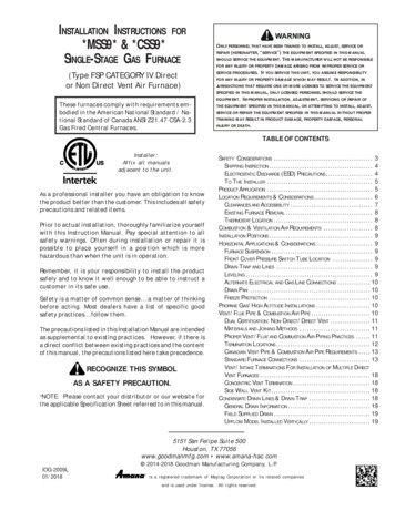
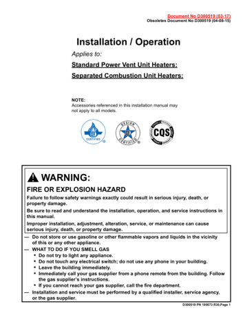
1.0 General(cont’d)1.3 WarrantyRefer to the limited warranty information on the Warranty Card in the “Literature Bag”.Warranty is void if .a. Wiring is not in accordance with the diagram furnished with the heater.b. The unit is installed without proper clearance to combustible materials.c. A fan model is connected to a duct system or if the air delivery system ismodified.1.4 InstallationCodesThese units must be installed in accordance with local building codes. In the absence oflocal codes, in the United States, the unit must be installed in accordance with the NationalFuel Gas Code, ANSI Z223.1. A Canadian installation must be in accordance with the CSAB149 Installation Codes. These codes are available from CSA Information Services, 1-800463-6727. Local authorities having jurisdiction should be consulted before installation ismade to verify local codes and installation procedure requirements.Special Installations(Aircraft Hangars/Repair Garages/Parking Garages)Installations in aircraft hangars should be in accordance with ANSI/NFPA No. 409 (latestCalifornia WarningLabelIf the heater is being installed in the state of California, the installer MUST attach a warninglabel on the outside of the access door. The California Warning label is shipped in the literature bag along with this manual, the warranty form, and any other paperwork that applies.MassachusettsRequirement2.0 Unit HeaterLocationedition), Standard for Aircraft Hangars; in public garages in accordance with ANSI/NFPA No.88A (latest edition), Standard for Parking Structures; and for repair garages in accordancewith ANSI/NFPA No. 88B (latest edition), Standard for Repair Garages. In Canada, installations in aircraft hangars should be in accordance with the requirements of the enforcingauthorities, and in public garages in accordance with CSA B149 codes.If installation is in California, select a location on the heater access panel. Be sure the surface is clean and dry and adhere the label.If the heater is being installed in the Commonwealth of Massachusetts, these units must beinstalled by a licensed plumber or licensed gas fitter.Use the sound data in Technical Data table in the APPENDIX (page 38), clearancesin Paragraph 4.1; the combustion air requirements in Paragraph 6.2; the throw tables,mounting height requirements, and location recommendations in Paragraphs 2.1 and2.2; the weights in Paragraph 5.1; and the venting requirements in the Venting Manualto determine where to suspend the heater.CAUTIONUnit heaters should not be used in an application where theheated space temperature is below 50 F. Operating under lowambient conditions may cause condensation to form in the heatexchanger.2.1 Heater ThrowFIGURE 1 - Throw forFan Models NOTE: Throws listed are with standard adjustable horizontal louvers at the angleslisted (angle is relative to the top of the heater). Throw pattern changes with the addition of optional vertical louvers and/or downturn nozzles.Page 4, D300519 PN 195673 R30
Dimensions X, Y, and Z (feet) Models with Standard Horizontal Louvers at Mounting Heights of 5 - 18 ftYZXYZXYZXYZ5 ft61430-21 71640-20 81845-16 92057-14 92059-18 102265-14 8 ft71326-39 91637-34 10 1842-29 122254-25 112156-28 122363-24 10 ft61122-52 91533-43 10 1739-37 122252-32 122052-36 132460-30 12 ft----81227-55 10 1634-46 122148-39 111947-44 142357-36 14 ft--------91429-56 121944-46 111742-51 142253-43 16 ft------------111738-54 101434-58 132047-50 18 ft--------------------111740-57 Angle*Y60LouverAngle*X45LouverAngle*30H8 ft132473-26 152890-22 16 3093-20 142786-24 162993-21 152894-24 1731105-20 1834113-17 10 ft142469-32 172987-27 17 3191-25 152782-30 173090-26 162889-29 1832103-25 2035110-21 12 ft142464-39 182984-32 18 3188-30 162778-35 183087-31 172885-34 193298-30 2136108-25 14 ft142259-45 182879-37 19 3084-34 162673-41 183083-36 172780-40 203295-34 2335105-29 16 ft132053-51 182774-42 19 2979-39 162467-47 192878-41 172574-45 213190-38 2335101-33 18 ft111744-58 172668-48 19 2874-44 142260-53 182772-46 162466-51 203085-43 233597-37 Dimensions X, Y, and Z (meters) Models with Standard Horizontal Louvers at Mounting Heights of 1.5 - 5.5MYZXYZXYZXYZ1.5 M 1.8 4.39.1-21 2.1 4.9 12.2 -20 2.4 5.5 13.8 -16 2.7 6.1 17.4 -14 2.7 6.1 18.0-18 3.0 6.7 19.9-14 2.4 M 2.1 4.07.9-39 2.7 4.9 11.3 -34 3.0 5.5 12.8 -29 3.7 6.7 16.5 -25 3.4 6.4 17.1-28 3.7 7.0 19.2-24 3.0 M 1.8 3.46.7-52 --2.7 4.6 10.0 -43 3.0 5.2 11.9 -37 3.7 6.7 15.8 -32 3.7 6.1 15.8-36 4.0 7.3 18.3-30 2.4 3.73.7 6.4 14.6 -39 3.4 5.8 14.3-44 4.3 7.0 17.4-36 -55 3.0 4.9 10.4 -46 4.3 M--------4.9 M----------5.5 M----------XYZXYZ-56 3.7 5.8 13.4 -46 3.4 5.2 12.8-51 4.3 6.7 16.1-43 --3.4 5.2 11.6 -54 3.0 4.3 10.4-58 4.0 6.1 14.3-50 ---3.4 5.2 12.2-57 --200LouverAngle*H175LouverAngle*1502.7 4.3 erAngle*-LouverAngle*-LouverAngle*3.7 uverAngle*X45LouverAngle*30H2.4 M 4.0 7.3 22.3 -26 4.6 8.5 27.4 -22 4.9 9.1 28.0 -20 4.3 8.2 26.2 -24 4.9 8.8 28.3-21 4.6 8.5 28.7-24 5.2 9.4 32.0 -20 5.5 11.3 34.4 -17 3.0 M 4.3 7.3 21.0 -32 5.2 8.8 26.6 -27 5.2 9.4 27.7 -25 4.6 8.2 25.0 -30 5.2 9.1 27.4-26 4.9 8.5 27.1-29 5.5 9.8 31.4 -25 6.1 10.7 33.5 -21 3.7 M 4.3 7.3 19.5 -39 5.5 8.8 25.6 -32 5.5 9.4 26.8 -30 4.9 8.2 23.8 -35 5.5 9.1 26.5-31 5.2 8.5 25.9-34 5.8 9.8 29.9 -30 6.4 11.0 32.9 -25 4.3 M 4.3 6.7 18.0 -45 5.5 8.5 24.1 -37 5.8 9.1 25.6 -34 4.9 7.9 22.3 -41 5.5 9.1 25.3-36 5.2 8.2 24.4-40 6.1 9.8 29.0 -34 7.0 10.7 32.0 -29 4.9 M 4.0 6.1 16.2 -51 5.5 8.2 22.6 -42 5.8 8.8 24.1 -39 4.9 7.3 20.4 -47 5.8 8.5 23.8-41 5.2 7.6 22.6-45 6.4 9.4 27.4 -38 7.0 10.7 30.8 -33 5.5 M 3.4 5.2 13.4 -58 5.2 7.9 20.7 -48 5.8 8.5 22.6 -44 4.3 6.7 18.3 -53 5.5 8.2 21.9-46 4.9 7.3 20.1-51 6.1 9.1 25.9 -43 7.0 10.7 26.9 -37 2.2 Location RecommendationsNOTE: Ventingrequirements mayaffect location.Consult the VentingManual for this heaterbefore making finaldetermination.Locate the heater so that it is a minimum of five feet (1.5M) above the floor and incompliance with the clearances in Paragraph 4.1.WARNINGIf touched, the vent pipe and internal heater surfaces that areaccessible from outside the heater will cause burns. Suspend theheater a minimum of 5 feet (1.5M) above the floor.For best results, the heater should be placed with certain rules in mind. In general, aunit should be located from 8 to 12 feet (2.4-3.7M) above the floor. Units should alwaysbe arranged to blow toward or along exposed wall surfaces, if possible. Where two ormore units are installed in the same room, a general scheme of air circulation shouldbe maintained for best results.Suspended heaters are most effective when located as close to the working zone aspossible, and this fact should be kept in mind when determining the mounting heightsto be used. However, care should be exercised to avoid directing the discharged airdirectly on the room occupants.Partitions, columns, counters, or other obstructions should be taken into considerationwhen locating the unit heater so that a minimum quantity of airflow will be deflected bysuch obstacles.D300519 PN 195673 R30,Page 5
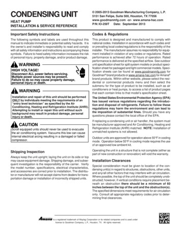
2.0 Unit HeaterLocation(cont’d)2.2 LocationRecommendations(cont’d)When units are located in the center of the space to be heated, the air should be discharged toward the exposed walls. In large areas, units should be located to dischargeair along exposed walls with extra units provided to discharge air in toward the centerof the area.At those points where infiltration of cold air is excessive, such as at entrance doors andshipping doors, it is desirable to locate the unit so that it will discharge directly towardthe source of cold air from a distance of 15 to 20 feet (4.6-6.1M).CAUTION: Do not locate the heater where it may be exposed towater spray, rain, or dripping water.For a location where dirt, dust, or other airborne contaminants are present in the indoorenvironment, it is recommended to install a separated-combustion unit, SeparatedCombustion model, that uses outside air for combustion. Using a separated-combustionunit will reduce the build-up of contaminants on the burner. Any buildup on the burnerwill adversely affect the combustion process.Hazards of Chlorine applies to SeparatedCombustion Heaterslocation with regard tothe combustion air inlet3.0 Uncrating andPreparation3.2 Preparing forInstallation3.2.1 Field-InstalledPartsThe presence of chlorine vapors in the combustion air of gas-fired heating equipmentpresents a potential corrosion hazard. Chlorine found usually in the form of freon ordegreaser vapors, when exposed to flame will precipitate from the compound, and gointo solution with any condensation that is present in the heat exchanger or associatedparts. The result is hydrochloric acid which readily attacks all metals including 300 gradestainless steel. Care should be taken to separate these vapors from the combustionprocess. This may be done by wise location of the unit vent and combustion airterminals with regard to exhausters or prevailing wind directions. Chlorine is heavierthan air. Keep these facts in mind when determining installation location of the heaterin relation to building exhaust systems.3.1 Uncrating and InspectingThis unit was test operated and inspected at the factory prior to crating and was inoperating condition. If the heater has incurred any damage in shipment, document thedamage with the transporting agency and contact an authorized Distributor. If you arean authorized Distributor, follow the FOB freight policy procedures.Check the rating plate for the gas specifications and electrical characteristics of theheater to be sure that they are compatible with the gas and electric supplies at theinstallation site.Read this booklet and become familiar with the installation requirements of your particular heater. If you do not have knowledge of local requirements, check with the localgas company or any other local agencies who might have requirements concerningthis installation. Before beginning, make preparations for necessary supplies, tools,and manpower.IMPORTANT: Shipping brackets are attached with cabinet screws. When removing shipping brackets, re-insert ALL screws into the cabinet.Models with Separated Combustion - In the literature bag, find three cap screws, P/N203311, and three sealing washers, P/N 61658. After attaching the hanging hardware(Paragraph 5.2), these screws and washers must be used to seal the unused holes inthe top of the heater.Models with Standard Power Vent - If the installation includes optional vertical louvers,downturn nozzle, ceiling mounting bracket, hanger kit, high altitude kit, multiple heatercontrol, sensor for DDC control, and/or stepdown transformer, install these optionsbefore the heater is suspended. Complete instructions are in this form or in theoption package; option packages are shipped separately.Other shipped separate items could include a vent cap (Standard Power Vent heaterswith Option CC1); a vent/combustion air kit (Separated Combustion heaters withOption CC2 or CC6); a manual gas valve; a thermostat bracket kit; a thermostat; and/or a thermostat guard. Be sure all options ordered are at the installation site.High Altitude Kit, Option DJ20 or DJ21If the heater is being installed at an elevation above 2000 ft (610M), the input rate willhave to be derated. This is done by adjusting the valve outlet pressure.Page 6, D300519 PN 195673 R30
In addition, if the heater is being installed at an altitude above 6000 ft (1830M), thepressure switch will have to be changed. If ordered with the unit as Option DJ20 orDJ21, the pressure switch is shipped separately for field installation.Gas valve adjustmentfor high altitude canonly be done afterheater is operating;see Paragraph 6.1.FIGURE 2 Installing HighAltitude PressureSwitch requiredabove 6000 ft(1830M) elevationAdjusting the valve outlet pressure is done after the heater is in operation; follow theinstructions in Paragraph 6.1. Capacities and inputs for derated units are also listed inParagraph 6.1.If the pressure switch needs to be changed, do that before the heater is operated; follow the instructions in FIGURE 2.Standard Power Vent ModelsSize30High Altitude Switch P/N456075100125150 175 200 225 250 300 350 pleBrownNegative Pressure OFF Setpoint "w.c.Label color201160Standard Power Vent Models with Option AV6 for Common VentingSize30High Altitude Switch P/N456075100197029 197032 196362 196388Negative Pressure OFF Setpoint "w.c.Label color0.600.450.550.50Lt BluePinkWhiteOrangeSeparated Combustion ModelsSize30High Altitude Switch P/NPressure Switch456075197029Differential Pressure OFF Setpoint "w.c.Label color100125196388 197030150 175 200 225 250 300 350 4001970312011600.600.500.400.351.05Lt. BlueOrangeGreenPurpleBrownInstructions for Changing Pressure Switch1.2.3.4.In the control compartment, locate the pressure switch.Mark and disconnect the two wires attached to the pressure switch.Disconnect the sensing tubes from the pressure switch.Locate the two screws holding the switch mounting bracket. Remove the screws and the pressure switch. Savethe screws.5. Using the same screws, install the high altitude pressure switch. Attach the sensing tubes and wires.Downturn Nozzle Kits,Option CD 2, 3, or 4(NOTE: Application specific)Follow the instructions with the kit to install. Additional length beyond the front of theunit is shown in FIGURE 3.FIGURE 3 -SizeWith OptionalDownturn NozzleDimension “U”-- Applies to StandardPower Vent (except asspecified) & SeparatedCombustion Models4.0 ClearancesandDimensionsClearancesSizeTopOptions CD2 and CD4Option CD3inchesmminchesmm30, 457-1/818112-3/831460, 758-5/821915381100, 12512-5/832121-7/8556150, 175, 20011-1/229219-7/8505225, 25014-1/236825-1/8638300, 350, 40018-1/2470328134.1 ClearancesUnits must be installed so that the clearances in the table are provided for combustionair space, inspection and service, and for proper spacing from combustible construction. Clearance to combustibles is defined as the minimum distance from the heaterto a surface or object that is necessary to ensure that a surface temperature of 90 F(50 C) above the surrounding ambient temperature is not exceeded.Flue ConnectorAccess PanelNon-Access nchesmminchesmm30 - 12512561521845712512518457150 - 400410261521845725112518457*Suspend the heater so that the bottom is a minimum of 5 feet (1.5M) above the floor.** Measure rear clearance from the fan motor.D300519 PN 195673 R30,Page 7
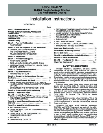
4.0 Clearances and Dimensions (cont’d)4.2 DimensionsFIGURE 4 - Standard Power Vent ModelsAngular corner(Only available oncertain models)Hand Pull (Only available oncertain models)“Finger Holes” (Only availableon certain models)Standard Power Vent Model Dimensions (inches 1/16)SizeABCDEFGHJKNPQR30, 4512-1/8 26-5/8 10 13-13/162621-9/16 5-3/166-1/217-3/8 11/16 4-5/16139-9/166015-1/8 26-5/8 13 13-13/162721-9/16 7-7/86-1/25-1/23-7/817-3/8 11/16 4-5/161310-1/27515-1/8 26-5/8 13 13-13/16 27-5/8 21-9/16 7-7/86-1/25-1/23-7/817-3/8 11/16 4-5/161310-1/210023-1/8 26-5/8 21 13-13/16 28-5/8 21-9/16 14-1/26-1/28-3/43-7/817-3/8 11/16 4-5/161310-1/212523-1/8 26-5/8 21 13-13/16 29-3/8 21-9/16 14-1/26-1/28-3/43-7/817-3/8 11/16 4-5/161310-1/2150, 175, 20020-1/8 38-3/16 168-1/45-7/166-1/2 25-11/16 1-3/8 8-3/16 22-3/16 16-3/8225, 25096-1/2 25-11/16 1-3/8 8-3/16 22-3/16 15-5/8300, 350, 400234235-3/826-1/8 38-3/16 22234235-3/8 13-1/16 8-13/1634-1/8234235-3/8 17-1/1641308-1/292-11/16 3-7/8M11-13/16 7-5/16 27-11/16 1-3/8 8-3/16 22-3/16 16-3/16Standard Power Vent Model Dimensions (mm 2)SizeABCDEFGHJKMNPQR30, 83681652229844117110330267150, 175, 5, 0, 350, age 8, D300519 PN 195673 R30
FIGURE 5 - Separated Combustion ModelsSeparated Combustion Model Dimensions (inches 1/16)SizeABCDEFGHJ30, 4512-1/8 26-5/810 13-13/162621-9/16 5-3/166-1/26015-1/8 26-5/813 13-13/162721-9/16 7-7/86-1/25-1/27515-1/8 26-5/813 13-13/16 27-5/8 21-9/16 7-7/86-1/25-1/210023-1/8 26-5/821 13-13/16 28-5/8 21-9/16 14-1/26-1/212523-1/8 26-5/821 13-13/16 29-3/8 21-9/16 14-1/2150, 175, 20020-1/8 38-3/16 16234235-3/8225, 25026-1/8 38-3/16 22234235-3/8 13-1/16 8-13/16300, 350, 40034-1/8234235-3/8 17-1/1641308-1/2KMNPQRST17-3/8 11/16 4-5/16139-9/16 2-15/16 2-15/163-7/817-3/8 11/16 4-5/161310-1/23-1/4 2-15/163-7/817-3/8 11/16 4-5/161310-1/23-1/4 2-15/168-3/43-7/817-3/8 11/16 4-5/161310-1/24-5/8 2-15/166-1/28-3/43-7/817-3/8 11/16 4-5/161310-1/28-1/45-7/166-1/2 25-11/16 1-3/8 8-3/16 22-3/16 16-3/892-11/16 3-7/894-5/8 2-15/164-1/88-5/166-1/2 25-11/16 1-3/8 8-3/16 22-3/16 15-5/8 5-9/16 8-5/1611-13/16 7-5/16 27-11/16 1-3/8 8-3/16 22-3/16 16-3/16 9-1/16 8-9/16Separated Combustion Model Dimensions (mm 2)SizeABCDEFGHJKMNPQRST30, 587676533351746150, 175, 7589921621013816565235208564416105211225, 250664970559584300, 350, 9 PN 195673 R30,Page 9
5.0 Hanging theHeater5.1 WeightsBefore suspending the heater, check the supporting structure to be used to verify thatit has sufficient load-carrying capacity to support the weight of the unit.Standard Power Vent ModelSize30456075100125150 175, 200 06kg2427303344467885929812213313912510246150 175, 200 138Separated Combustion NGSCheck the supporting structure to be used to verify that it has sufficientload carrying capacity to support the weight of the unit. Suspend theheater only from the threaded nut retainers or with a manufacturerprovided kit. Do NOT suspend from the heater cabinet.5.1.1 Field-Removalof Heat ExchangerTube Support - ModelSizes 30 thru 125(Optional)In some cases, the heat exchanger tubes could shift during shipment, causing vibrationnoise against the support during unit operation. The primary function of the heatexchanger tube support is to support the heat exchanger tubes during shipment. Thissupport can be removed without affecting the operation of the unit. It is recommendedthat the support be removed prior to installing the unit.Listed below is the steps needed to remove this support: Remove the discharge air louvers. Be careful not to lose the springs. Remove and discard the two screws located on top of the unit that secure theheat exchanger support. Remove the heat exchanger support through the discharge opening and discardthe support. Reinstall the discharge air louvers.5.2 Lifting and SuspendingFIGURE 6 - SeparatedCombustion Models- Plug the unusedsuspension points onthe control side of theheater with the three1/2” long screws, P/N203311, and the threesealing washers, P/N61658. Find the screwsand washers in theliterature bag shippedinside the heater.When the heater is lifted for suspension, support the bottom of the heater with plywoodor other appropriately placed material. If the bottom is not supported, damage couldoccur. Before hanging, verify that any screws used for holding shipping brackets werere-installed in the cabinet.Separated Combustion Models - Whether using the suspension points or a hangerkit, when installing a Separated Combustion Model, any unused suspension pointson the control side of the heater MUST be plugged. Plug these holes with the 1/2”long cap screws and flat washers shipped in the bag with the heater. (See FIGURE 6.)WARNINGUnit must be level for proper operation. Do not place or add additionalweight to the suspended heater. Hazard Levels, page 2.Page 10, D300519 PN 195673 R30
5.2.1 Two-Point or Four-Point SuspensionThe heater is equipped for either two-point or four-point suspension. A 3/8”-16 threadednut retainer is located at each suspension point. NOTE: Four-point suspension is requiredwhen installing an optional downturn nozzle. See Dimensions in Paragraph 4.2 and theillustration in FIGURE 7A.FIGURE 7A Suspending theHeater with Rods fromthe Threaded NutRetainers (either two orfour point suspension)Be sure the threaded hanger rods arelocked to the heater as illustrated.Length of threaded rod extending intothe heater MUST NOT exceed 1/2”(13mm).Recommended maximumhanger rod length is6 feet (1.8M).3/8 threaded rod(field supplied)Add a 3/8 nutand washer tolock the hangerrod to the heater.5.2.2 Hanger Kits, Option CK8, CK10, and CK22If ordered with swivel connectors for 1” pipe, Option CK8 or CK10, attach the swivelsat the threaded nut retainers. Suspend with 1” pipe. (See FIGURE 7B.)FIGURE 7B - SwivelConnectors to Suspendthe Heater from 1”Pipe, Option CK8 (2-pt)or CK10 (4-pt)Be sure thethreaded swivelconnectorsare locked tothe heater asillustrated. If ordered with a ceiling suspension kit, Option CK22, follow the illustrated instructionsin the kit. (See FIGURE 8.)FIGURE 8 - Suspendingthe Heater usingOption CK22, CeilingSuspension Kit (nohanger rods)Available forSizes 30-125.Allows theheater to beinstalled oneinch from theceiling.UDA Series ModelShown6.0 Mechanical6.1 Gas Piping andPressures6.1.1 Gas Supply and ConnectionsWARNINGThis appliance is equipped for a maximum gas supply pressure of 1/2psi, 3.5 kPa, or 14 inches wat
installation of this heater. 1.2 General Installation Information Venting Instruction Manuals Look for Matching Label on Venting Manual and Heater for Indoor Power Vent Units: Standard Power Vent Installation (Each heater has its own dedicated vent.) Label with a RED SQUARE for Indoor Fan Assist Units: (Sizes 30, 45, 60, 75 & 100 only)